Page 273 of 1807

BO0QI-01
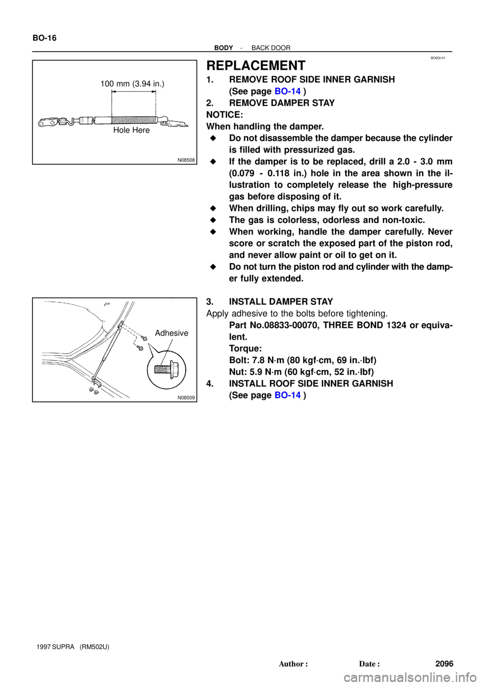
N08508
100 mm (3.94 in.)
Hole Here
N08509
Adhesive BO-16
- BODYBACK DOOR
2096 Author�: Date�:
1997 SUPRA (RM502U)
REPLACEMENT
1. REMOVE ROOF SIDE INNER GARNISH
(See page BO-14)
2. REMOVE DAMPER STAY
NOTICE:
When handling the damper.
�Do not disassemble the damper because the cylinder
is filled with pressurized gas.
�If the damper is to be replaced, drill a 2.0 - 3.0 mm
(0.079 - 0.118 in.) hole in the area shown in the il-
lustration to completely release the high-pressure
gas before disposing of it.
�When drilling, chips may fly out so work carefully.
�The gas is colorless, odorless and non-toxic.
�When working, handle the damper carefully. Never
score or scratch the exposed part of the piston rod,
and never allow paint or oil to get on it.
�Do not turn the piston rod and cylinder with the damp-
er fully extended.
3. INSTALL DAMPER STAY
Apply adhesive to the bolts before tightening.
Part No.08833-00070, THREE BOND 1324 or equiva-
lent.
Torque:
Bolt: 7.8 N´m (80 kgf´cm, 69 in.´lbf)
Nut: 5.9 N´m (60 kgf´cm, 52 in.´lbf)
4. INSTALL ROOF SIDE INNER GARNISH
(See page BO-14)
Page 528 of 1807
CO08J-01
- COOLINGCOOLANT
CO-1
1414 Author�: Date�:
1997 SUPRA (RM502U)
COOLANT
INSPECTION
1. CHECK ENGINE COOLANT LEVEL AT RADIATOR RESERVOIR
The engine coolant level should be between the ºLOWº and ºFULLº lines, when the engine is cold.
If low, check for leaks and add engine coolant up to the ºFULLº line.
2. CHECK ENGINE COOLANT QUALITY
(a) Remove the radiator cap.
CAUTION:
To avoid the danger of being burned, do not remove the radiator cap while the engine and radiator
are still hot, as fluid and steam can be blown out under pressure.
(b) There should not be any excessive deposits of rust or scale around the radiator cap or radiator filler
hole, and the coolant should be free from oil.
If excessively dirty, replace the coolant.
(c) Reinstall the radiator cap.
Page 570 of 1807

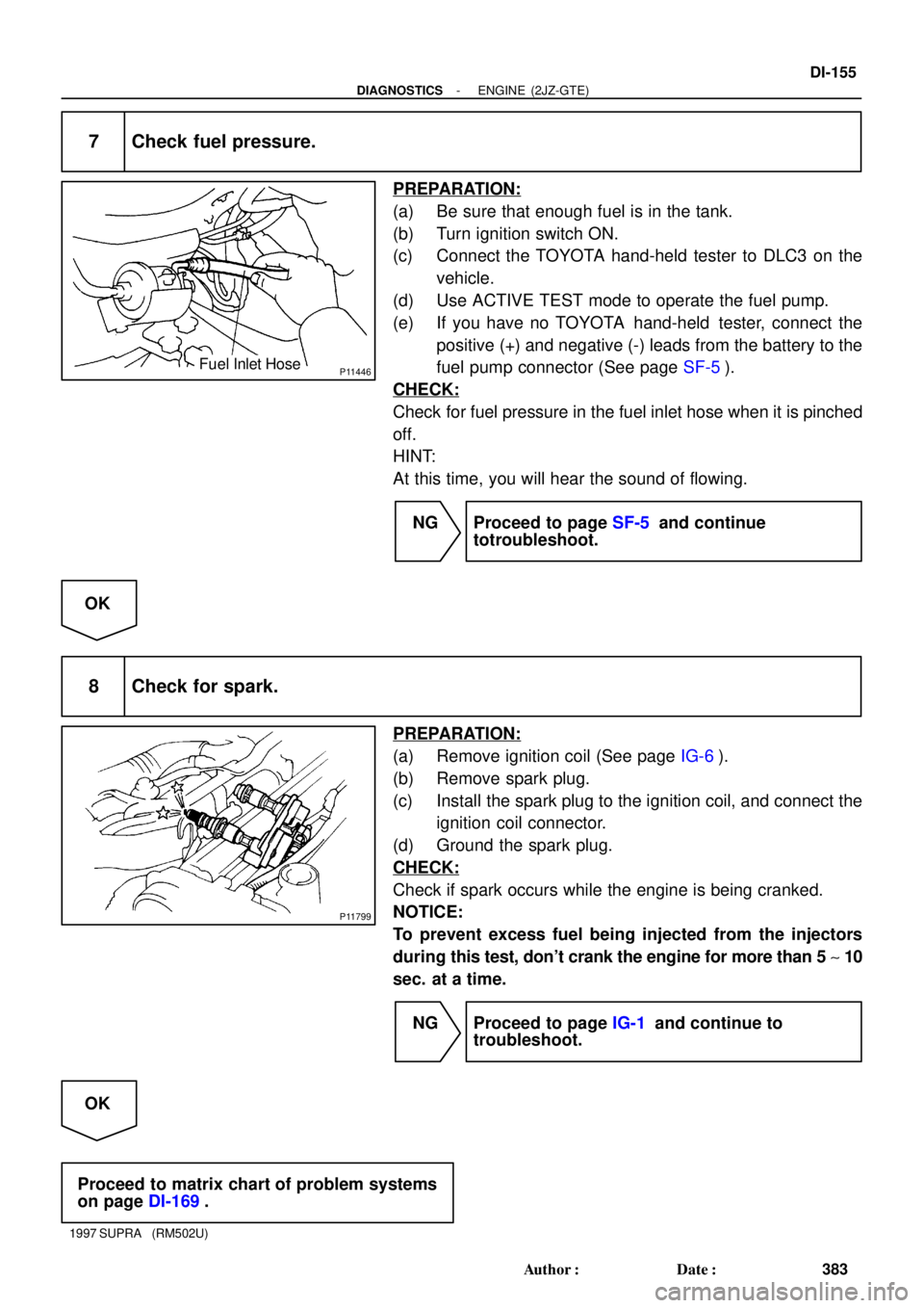
P11446Fuel Inlet Hose
P11799
- DIAGNOSTICSENGINE (2JZ-GTE)
DI-155
383 Author�: Date�:
1997 SUPRA (RM502U)
7 Check fuel pressure.
PREPARATION:
(a) Be sure that enough fuel is in the tank.
(b) Turn ignition switch ON.
(c) Connect the TOYOTA hand-held tester to DLC3 on the
vehicle.
(d) Use ACTIVE TEST mode to operate the fuel pump.
(e) If you have no TOYOTA hand-held tester, connect the
positive (+) and negative (-) leads from the battery to the
fuel pump connector (See page SF-5).
CHECK:
Check for fuel pressure in the fuel inlet hose when it is pinched
off.
HINT:
At this time, you will hear the sound of flowing.
NG Proceed to page SF-5 and continue
totroubleshoot.
OK
8 Check for spark.
PREPARATION:
(a) Remove ignition coil (See page IG-6).
(b) Remove spark plug.
(c) Install the spark plug to the ignition coil, and connect the
ignition coil connector.
(d) Ground the spark plug.
CHECK:
Check if spark occurs while the engine is being cranked.
NOTICE:
To prevent excess fuel being injected from the injectors
during this test, don't crank the engine for more than 5 ~ 10
sec. at a time.
NG Proceed to page IG-1 and continue to
troubleshoot.
OK
Proceed to matrix chart of problem systems
on page DI-169.
Page 578 of 1807
DI4SJ-01
S04073
Throttle Control ECU
VSV for Intake
Air Control Valve
(VSV1)
VSV for EXhaust
Bypass Valve
(VSV3) Heated Oxygen Sensor
(Bank 1 Sensor 1)
Ignition Coil
Mass Air Flow Meter
(Intake Air Temp. Sensor)
Engine Coolant Temp.
Sensor
VSV for Exhaust
Gas Control Valve
(VSV 2)
VSV for Waste
Gate Valve
(VSV4)VSV for EGR
ECM
IAC Valve
DLC1EGR Gas Temp. Sensor
Ignition Switch
Combination Meter
& Telltale Light RH
Fuel Pump ECU
Fuel Pump
No.1 Vehicle Speed Sensor
DLC3
Park/Neutral Position Switch
Stop Light Switch
Heated Oxygen Sensor
(Bank 1 Sensor 2) Igniter
Knock Sensor 2
Camshaft Position Sensor No.2
VSV for EVAP
Turbo Pressure Sensor
Camshaft Position Sensor No.1
Throttle Position Sensor
Sub Throttle Actuator Knock Sensor 1
Sub Throttle Position Sensor
Crankshaft Position Sensor
- DIAGNOSTICSENGINE (2JZ-GTE)
DI-163
391 Author�: Date�:
1997 SUPRA (RM502U)
PARTS LOCATION
Page 1024 of 1807

Position of Parts in Engine Compartment
E 4 Engine Coolant Temp. Sender
E 5 Engine Coolant Temp. SW
E 6 Engine Hood Courtesy SW
E 7 Engine Oil Level Sensor
F 3 Front Fog Light LH
F 4 Front Fog Light RH
F 5 Front Side Marker Light LH
F 6 Front Side Marker Light RH
F 7 Front Turn Signal Light LH
F 8 Front Turn Signal Light RH and Parking Light RH
F 9 Front Wiper Motor
G 1 Generator
G 2 Generator
H 1 Headlight Hi LH
H 2 Headlight Hi RH
H 3 Headlight Lo LH
H 4 Headlight Lo RH
H 5 Heated Oxygen Sensor (Bank 1 Sensor 1)
H 8 Horn LH
H 9 Horn RH A 1 A/C Ambient Temp Sensor
A 2 A/C Condensor Fan Motor
A 3 A/C Triple Pressure SW
(A/C Dual and Single Pressure SW)
A 4 A/C Magnetic Clutch and Lock Sensor
A 5 A/T Fluid Temp. Sensor
A 6 ABS Actuator
A 7 ABS Actuator
A10 ABS Speed Sensor Front LH
A11 ABS Speed Sensor Front RH
B 1 Back-Up Light SW (M/T)
B 2 Brake Fluid Level Warning SW
C 1 Camshaft Position Sensor No.1
C 2 Camshaft Position Sensor No.2
C 3 Crankshaft Position Sensor
C 4 Cruise Control Actuator
D 1 Data Link Connector 1
D 2 Daytime Running Light Relay No.3
D 3 Daytime Running Light Relay No.3
E 1 EGR Gas Temp. Sensor
E 2 Electronically Controlled Transmission Solenoid
E 3 Engine Coolant Temp. Sensor
[2JZ-GTE]
24
26
G ELECTRICAL WIRING ROUTING
Page 1025 of 1807
![TOYOTA SUPRA 1997 Service Repair Manual Position of Parts in Engine Compartment
[2JZ-GTE]
R 1 Radiator Fan Motor No.1
R 2 Radiator Fan Relay No.1
R 3 Radiator Fan Relay No.2
R20 Radiator Fan Motor No.2
S 1 SFI Resistor
S 2 Starter
S 3 Start TOYOTA SUPRA 1997 Service Repair Manual Position of Parts in Engine Compartment
[2JZ-GTE]
R 1 Radiator Fan Motor No.1
R 2 Radiator Fan Relay No.1
R 3 Radiator Fan Relay No.2
R20 Radiator Fan Motor No.2
S 1 SFI Resistor
S 2 Starter
S 3 Start](/manual-img/14/57469/w960_57469-1024.png)
Position of Parts in Engine Compartment
[2JZ-GTE]
R 1 Radiator Fan Motor No.1
R 2 Radiator Fan Relay No.1
R 3 Radiator Fan Relay No.2
R20 Radiator Fan Motor No.2
S 1 SFI Resistor
S 2 Starter
S 3 Starter
S 5 Sub Throttle Position Sensor
S18 Sub Throttle Valve Motor
T 1 Theft Deterrent Horn
T 2 Throttle Position Sensor
T14 Turbo Pressure Sensor
V 2 VSV (EGR)
V 3 VSV (EVAP)
V 4 VSV (Exhaust Bypass Valve)
V 5 VSV (Exhaust Gas Control Valve)
V 6 VSV (Fuel Pressure Up)
V 7 VSV (Intake Air Control Valve)
V 8 VSV (Waste Gate Valve)
V10 Vehicle Speed Sensor No.1 (Combination Meter)
V11 Vehicle Speed Sensor No.2 (Electronically
Controlled Transmission)
W 1 Washer Motor I 1 Idle AIr Control Valve
I 2 Igniter
I 3 Igniter
I 6 Ignition Coil No.1
I 7 Ignition Coil No.2
I 8 Ignition Coil No.3
I 9 Ignition Coil No.4
I10 Ignition Coil No.5
I11 Ignition Coil No.6
I12 Injector No.1
I13 Injector No.2
I14 Injector No.3
I15 Injector No.4
I16 Injector No.5
I17 Injector No.6
K 1 Knock Sensor (on Front Side)
K 2 Knock Sensor (on Rear Side)
M 1 Mass Air Flow Meter
N 1 Noise Filter
O 1 O/D Direct Clutch Speed Sensor
O 2 Oil Pressure SW
P 1 PPS Solenoid
P 2 Park/Neutral Position SW, Back-Up Light SW and
A/T Indicator Light SW (A/T)
P13 Parking Light LH
25
G
Page 1026 of 1807
26
G ELECTRICAL WIRING ROUTING
Position of Parts in Engine Compartment
[2JZ-GE]
E 1 EGR Gas Temp. Sensor
E 2 Electronically Controlled Transmission Solenoid
E 3 Engine Coolant Temp. Sensor
E 4 Engine Coolant Temp. Sender
E 6 Engine Hood Courtesy SW
E 7 Engine Oil Level Sensor
F 3 Front Fog Light LH
F 4 Front Fog Light RH
F 5 Front Side Marker Light LH
F 6 Front Side Marker Light RH
F 7 Front Turn Signal Light LH
F 8 Front Turn Signal Light RH and Parking Light RH
F 9 Front Wiper Motor
G 1 Generator
G 2 Generator A 1 A/C Ambient Temp. Sensor
A 3 A/C Dual Pressure SW
A 4 A/C Magnetic Clutch and Lock Sensor
A 5 A/T Fluid Temp. Sensor
A 6 ABS Actuator
A 7 ABS Actuator
A 8 ABS Relay
A 9 ABS Relay
A10 ABS Speed Sensor Front LH
A11 ABS Speed Sensor Front RH
B 1 Back-Up Light SW (M/T)
B 2 Brake Fluid Level Warning SW
C 3 Crankshaft Position Sensor
C 4 Cruise Control Actuator
D 1 Data Link Connector 1
D 4 Distributor
Page 1027 of 1807
![TOYOTA SUPRA 1997 Service Repair Manual 27
G
Position of Parts in Engine Compartment
[2JZ-GE]
O 2 Oil Pressure SW
P 1 PPS Solenoid
P 2 Park/Neutral Position SW, Back-Up Light SW and
A/T Indicator Light SW (A/T)
P 3 Power Steering Pressure S TOYOTA SUPRA 1997 Service Repair Manual 27
G
Position of Parts in Engine Compartment
[2JZ-GE]
O 2 Oil Pressure SW
P 1 PPS Solenoid
P 2 Park/Neutral Position SW, Back-Up Light SW and
A/T Indicator Light SW (A/T)
P 3 Power Steering Pressure S](/manual-img/14/57469/w960_57469-1026.png)
27
G
Position of Parts in Engine Compartment
[2JZ-GE]
O 2 Oil Pressure SW
P 1 PPS Solenoid
P 2 Park/Neutral Position SW, Back-Up Light SW and
A/T Indicator Light SW (A/T)
P 3 Power Steering Pressure SW
P13 Parking Light LH
S 2 Starter
S 3 Starter
T 1 Theft Deterrent Horn
T 2 Throttle Position Sensor
V 1 VSV (ACIS)
V 2 VSV (EGR)
V 3 VSV (EVAP)
V 6 VSV (Fuel Pressure Up)
V10 Vehicle Speed Sensor No.1 (Combination Meter)
V11 Vehicle Speed Sensor No.2 (Electronically
Controlled Transmission)
W 1 Washer Motor H 1 Headlight Hi LH
H 2 Headlight Hi RH
H 3 Headlight Lo LH
H 4 Headlight Lo RH
H 8 Horn LH
H 9 Horn RH
I 1 Idle Air Control Valve
I 4 Igniter
I 5 Ignition Coil
I 12 Injector No.1
I 13 Injector No.2
I 14 Injector No.3
I 15 Injector No.4
I 16 Injector No.5
I 17 Injector No.6
K 1 Knock Sensor (on Front Side)
K 2 Knock Sensor (on Rear Side)
M 1 Mass Air Flow Meter
M 2 Main Heated Oxygen Sensor (Bank 1 Sensor 1)
M 3 Main Heated Oxygen Sensor (Bank 2 Sensor 1)
N 1 Noise Filter