Page 1740 of 1807

177 Author�: Date�:
1997 SUPRA (RM502U)
SFI (2JZ-GTE)
SERVICE DATA
Fuel pressure
regulatorFuel pressure at no vacuum226 - 275 kPa (2.3 - 2.8 kgf/")
SS0DU-02
SS-20
- SERVICE SPECIFICATIONSSFI (2JZ-GTE)
177 Author�: Date�:
1997 SUPRA (RM502U)
SFI (2JZ-GTE)
SERVICE DATA
Fuel pressure
regulatorFuel pressure at no vacuum226 - 275 kPa (2.3 - 2.8 kgf/cm2, 33 - 40 psi)
Fuel pumpResistance at 20°C (68°F)0.1 - 3.0 W
InjectorResistance at 20°C (68°F)
Injection volume
Difference between each cylinder
Fuel leakageApprox. 1.95 W
111 - 141 cm3 (6.8 - 8.6 cu in.) per 15 sec.
10 cm3 (0.6 cu in.) or less
One drop or less per minutes
MAF meterResistance (THA - E2) at -20°C (-4°F)
at 0°C (32°F)
at 20°C (68°F)
at 40°C (104°F)
at 60°C (140°F)10 - 20 kW
4 - 7 kW
2 - 3 kW
0.9 - 1.3 kW
0.4 - 0.7 kW
Throttle bodyThrottle body fully closed angle
Dashpot setting speed
Throttle opener setting speed10°
2,300 ± 400 rpm
1,500 ± 200 rpm
Throttle
position
sensorClearance between stop screw and lever
0 mm (0 in.) VTA - E2
0.54 mm (0.021 in.)IDL - E2
0.70 mm (0.028 in.)IDL - E2
Throttle valve fully open VTA - E2
- VC - E2
0.34 - 6.3 kW
0.5 kW or less
Infinity
2.4 - 11.2 kW
3.1 - 7.2 kW
Sub-throttle
position
sensorClearance between stop screw and lever
0 mm (0 in.) VTA - E2
0.41 mm (0.016 in.)IDL - E2
0.48 mm (0.019 in.)IDL - E2
Throttle valve fully open VTA - E2
- VC - E2
0.3 - 6.3 kW
0.5 kW or less
Infinity
2.0 - 10.8 kW
3.5 - 6.5 kW
Sub-throttle
actuatorResistance (A and A-, B and B-)
at 20°C (68°F)
0.82 - 0.98 W
IAC valveResistance (B1 (or B2) - Others) at cold
at hot15 - 25 W
20 - 30 W
Solenoid
resistorResistance (+B - Others) at 20°C (68°F)Approx. 6 W
VSV for fuel
pressure controlResistance at 20°C (68°F)33 - 39 W
VSV for intake
air control valveResistance at 20°C (68°F)38.5 - 44.5 W
VSV for exhaust
bypass valveResistance at 20°C (68°F)22 - 26 W
VSV for waste
gate valveResistance at 20°C (68°F)22 - 26 W
VSV for
exhaust gas
control valveResistance at 20°C (68°F)38.5 - 44.5 W
VSV for EVAPResistance at 20°C (68°F)30 - 34 W
EGR gas
temperature
sensorResistance at 50°C (122°F)
at 100°C (212°F)
at 150°C (302°F)64 - 97 kW
11 - 16 kW
2 - 4 kW
Page 1741 of 1807
- SERVICE SPECIFICATIONSSFI (2JZ-GTE)
SS-21
178 Author�: Date�:
1997 SUPRA (RM502U) ECT sensor
Resistance at -20°C (-4°F)
at 0°C (32°F)
at 20°C (68°F)
at 40°C (104°F)
at 60°C (140°F)
at 80°C (176°F)10 - 20 kW
4 - 7 kW
2 - 3 kW
0.9 - 1.3 kW
0.4 - 0.7 kW
0.2 - 0.4 kW
VSV for EGRResistance at 20°C (68°F)30 - 34 W
Heated oxygen
sensorHeater coil resistance at 20°C (68°F)11 - 16 W
Fuel cut rpmFuel return rpm1,400 rpm
Page 1742 of 1807

179 Author�: Date�:
1997 SUPRA (RM502U)
TORQUE SPECIFICATION
Part tightenedN´mkgf´cmft´lbf
Fuel line for union bolt
for flare nut29
30300
3102")
SS0DV-02
SS-22
- SERVICE SPECIFICATIONSSFI (2JZ-GTE)
179 Author�: Date�:
1997 SUPRA (RM502U)
TORQUE SPECIFICATION
Part tightenedN´mkgf´cmft´lbf
Fuel line for union bolt
for flare nut29
30300
31022
22
Fuel pressure regulator x Delivery pipe8.89078 in.´lbf
Fuel return pipe x Fuel pressure regulator2728020
Delivery pipe x Intake manifold2121015
Injector holder x Delivery pipe7.88069 in.´lbf
Fuel inlet pipe x Delivery pipe4142030
Air intake chamber x Intake manifold2728020
Manifold stay x Air intake chamber3940029
Manifold stay x Cylinder head3940029
EGR pipe x Cylinder head2728020
EGR pipe x EGR valve6465047
Control cable bracket x Air intake chamber1919514
Air intake chamber stay x Intake manifold1919514
Air intake chamber stay x Control cable bracket1919514
Fuel pressure pulsation damper x Fuel pipe support
for SST41
35420
35030
25
Fuel tank band x Body3940029
MAF meter x Air cleaner case6.97061 in.´lbf
Throttle body x Air intake chamber2121015
IAC valve x Air intake chamber2121015
EGR gas temperature sensor x EGR valve2020014
Knock sensor x Cylinder block4445033
Main heated oxygen sensor x Exhaust manifold2020014
Sub heated oxygen sensor x Center exhaust pipe2020014
Upper front crossmember extension x Front suspension Bolt
Nut29
33300
34022
25
Front lower arm bracket stay x Front suspension Bolt
Nut44
59450
60033
43
Page 1778 of 1807
700
630 - 770
1,000915 - 1,115
2,0001,920 - 2,220
3,0002,890 - 3,350
4,0003,940 - 4,400
5,0005,025 - 5,425
6,5006")
SS-66
- SERVICE SPECIFICATIONSBODY ELECTRICAL
223 Author�: Date�:
1997 SUPRA (RM502U)700
630 - 770
1,000915 - 1,115
2,0001,920 - 2,220
3,0002,890 - 3,350
4,0003,940 - 4,400
5,0005,025 - 5,425
6,5006,650 - 6,950
7,0007,025 - 7,625
OD/TRIP METER
(Connector Connected)
1 - Ground (Ignition switch position ON)Battery positive voltage
4 - Ground (Light Control switch position TAIL or HEAD)Battery positive voltage
5 - 7 (Ignition switch ON and drive the vehicle slowly)0V e Battery positive voltage
6 - 7 (Ignition switch ON and drive the vehicle slowly)0V e more than 5V
8 - Ground (Constant)Battery positive voltage
10 - Ground (Ignition SW ON, Light Control SW TAIL or
HEAD and turn the Light Control Rheostat knob to clockwise)6V " 0V
FUEL RECEIVER GAUGE
Between terminalsResistance (W)
A - BApprox. 269.7
A - CApprox. 123.5
B - CApprox. 146.2
FUEL SENDER GAUGE
Float position: mm (in.)Resistance (W)
F: Approx. 33.8 (1.331)Approx. 4.0
1/2: Approx. 44.8 (1.764)Approx. 55.0
E: Approx. 141.1 (5.555)Approx. 107.0
ENGINE COOLANT TEMPERATURE RECEIVER GAUGE
Between terminalsResistance (W)
A - BApprox. 229.7
A - CApprox. 54.0
B - CApprox. 175.7
ENGINE COOLANT TEMPERATURE SENDER GAUGE
Temperature °C (°F)Resistance (W)
50 (122.0)160 - 240
120 (248.0)17.1 - 21.2
LIGHT FAILURE SENSOR
3 - Ground (Light Control SW position OFF)No voltage
3 - Ground (Light Control SW position TAIL or HEAD)Battery positive voltage
4 - Ground (Ignition SW position LOCK or ACC)No voltage
4 - Ground (Ignition SW position ON)Battery positive voltage
7 - Ground (Stop Light SW position OFF)No voltage
7 - Ground (Stop Light SW position ON)Battery positive voltage
8 - Ground (Engine stop)No voltage
8 - Ground (Engine running)Battery positive voltage
INTEGRATION RELAY
Page 1784 of 1807

(Check Procedure and Correction Method)
Check intake air system, and repair or replace parts
as necessary. (See page TC-5)
Check intake air system, and repair or replace part")
TC037-01
(Possible Cause)
(Check Procedure and Correction Method)
Check intake air system, and repair or replace parts
as necessary. (See page TC-5)
Check intake air system, and repair or replace parts
as necessary. (See page TC-5)
Check exhaust system, and repair or replace parts
as necessary. (See page TC-5)
Check exhaust system, and repair or replace parts
as necessary. (See page TC-5) Check turbocharging pressure. (See page TC-5)
Turbocharging pressure:
61 - 75 kPa
(0.62 - 0.76 kgf/cm2, 8.8 - 10.8 psi)
If the pressure is below specifications, begin
diagnosis from item 2.
Check rotation of turbine shaft. If it does not turn or
turns with a heavy drag, replace the turbocharger
assembly.
Check axial and radial play of turbine shaft.
(See page TC-18)
Maximum axial play : 0.110 mm (0.0045 in.)
Maximum radial play: 0.173 mm (0.0068 in.)
If the play is greater than maximum, replace the
turbocharger assembly.
3. LEAK IN INTAKE AIR SYSTEM
4. RESTRICTED EXHAUST SYSTEM
6. ERRATIC TURBOCHARGER 5. LEAK IN EXHAUST SYSTEM
OPERATION 1. TURBOCHARGING PRESSURE
TOO LOW
2. RESTRICTED INTAKE SYSTEM
- TURBOCHARGING (2JZ-GTE)TROUBLESHOOTING
TC-1
1201 Author�: Date�:
1997 SUPRA (RM502U)
TROUBLESHOOTING
PROBLEM SYMPTOMS TABLE
HINT:
Before troubleshooting the turbocharger, first check the engine itself. (Valve clearance, engine compression,
ignition timing etc.)
1. INSUFFICIENT ACCELERATION, LACK OF POWER OR EXCESSIVE FUEL CONSUMPTION
Page 1785 of 1807
 (Check Procedure and Correction Method)
Check for deformed exhaust pipe, loose mounting
bolts or damaged gasket, and repair or replace as
necessary.
Refer to item 6 of INSUFFICIENT AC")
(Possible cause) (Check Procedure and Correction Method)
Check for deformed exhaust pipe, loose mounting
bolts or damaged gasket, and repair or replace as
necessary.
Refer to item 6 of INSUFFICIENT ACCELERATION,
LACK OF POWER OR EXCESSIVE FUEL
CONSUMPTION.
Check for loose, improperly installed or deformed
insulator mounting bolts, and repair or replace as
necessary.1. TURBOCHARGING HEAT
INSULATOR
2. EXHAUST PIPE LEAKING
VIBRATING
3. ERRATIC TURBOCHARGER
OPERATION
(Possible Cause)(Check Procedure and Correction Method)
Check for oil leakage in exhaust system
� Remove the turbine elbow from the turbocharger
and check for excessive carbon deposits on the
turbine wheel. Excessive carbon deposits
indicate a faulty turbocharger.
Check for oil leakage in intake air system.
� Check for axial and radial play of turbine shaft
and replace the turbocharger if necessary.
(See page TC-18)
Maximum axial play : 0.110 mm (0.0045 in.)
Maximum radial play : 0.173 mm (0.0068 in.)
Some oil mist in the blowby from the PCV is
Do not mistake it for an oil leak from the
turbocharger.
FAULTY TURBOCHARGER SEAL
NOTICE:
normal.
TC-2
- TURBOCHARGING (2JZ-GTE)TROUBLESHOOTING
1202 Author�: Date�:
1997 SUPRA (RM502U)
2. ABNORMAL NOISE
3. EXCESSIVE OIL CONSUMPTION OR WHITE EXHAUST
Page 1787 of 1807
P11352
TC-4
- TURBOCHARGING (2JZ-GTE)TURBOCHARGER
1204 Author�: Date�:
1997 SUPRA (RM502U)
11. IF REPLACING TURBOCHARGER, POUR APPROX.
20 cm
3 (1.2 cu in.) OF FRESH OIL INTO TURBOCHAR-
GER OIL INLET AND TURN IMPELLER WHEEL BY
HAND TO SPREAD OIL TO BEARING
12. IF OVERHAULING OR REPLACING ENGINE, CUT
FUEL SUPPLY AFTER REASSEMBLY AND CRANK
ENGINE FOR 30 SECONDS TO DISTRIBUTE OIL
THROUGHOUT ENGINE. THEN ALLOW ENGINE TO
IDLE FOR 60 SECONDS
Page 1804 of 1807
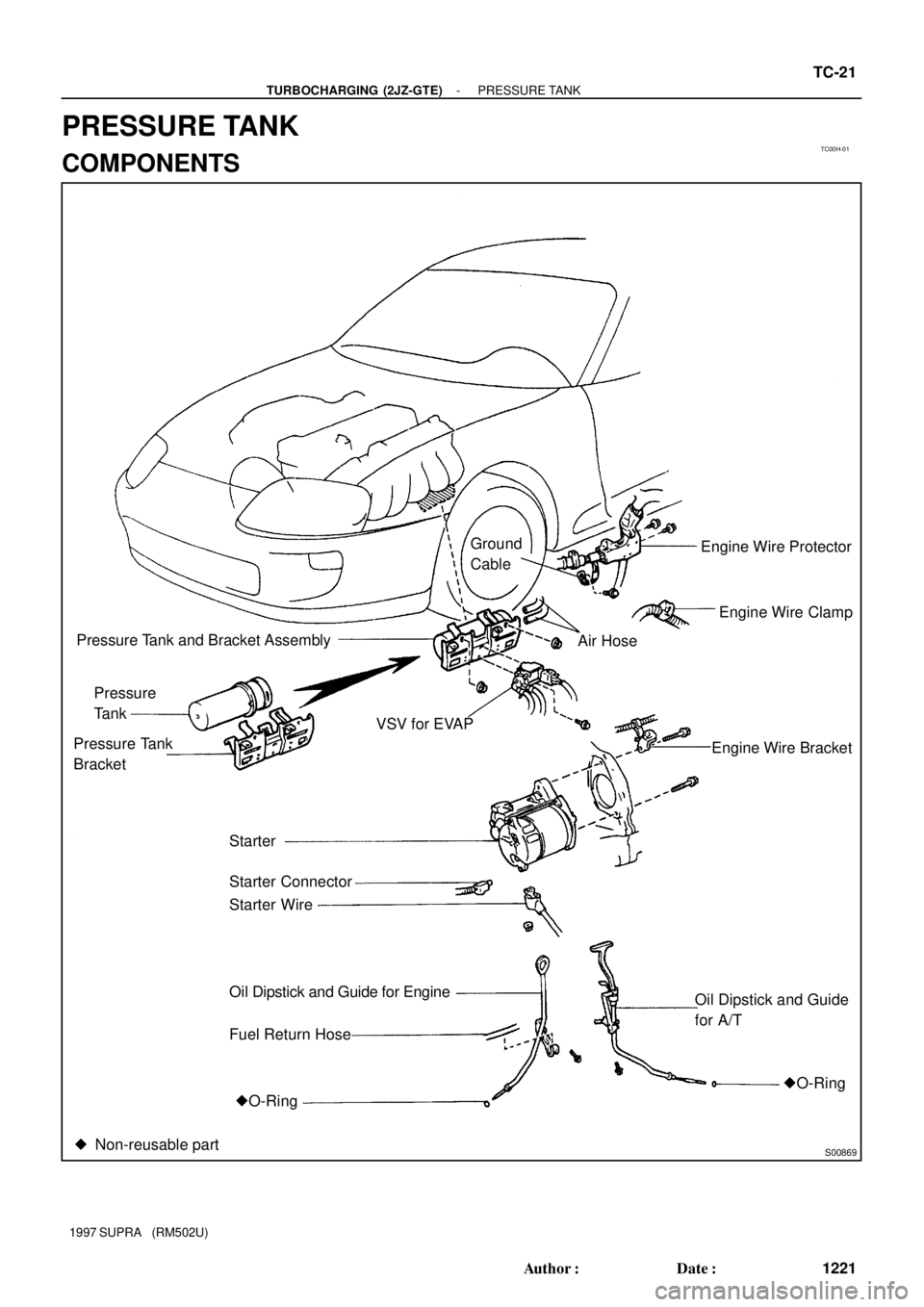
TC00H-01
S00869
Engine Wire Protector
Engine Wire Clamp
Engine Wire Bracket VSV for EVAPAir Hose
Oil Dipstick and Guide
for A/T Ground
Cable
�O-Ring Pressure
Tank
Pressure Tank and Bracket Assembly
Starter Pressure Tank
Bracket
Fuel Return Hose Oil Dipstick and Guide for Engine Starter Wire Starter Connector
�O-Ring
� Non-reusable part
- TURBOCHARGING (2JZ-GTE)PRESSURE TANK
TC-21
1221 Author�: Date�:
1997 SUPRA (RM502U)
PRESSURE TANK
COMPONENTS