1997 TOYOTA SUPRA door lock
[x] Cancel search: door lockPage 1006 of 1807

7
B
Q :Explains the system outline.
R :Indicates values or explain the function for reference during troubleshooting.
S :Indicates the reference page showing the position on the vehicle of the parts in the system circuit.
Example: Part P 4º (Power Window Master SW) is on page 21 of the manual.
* The letter in the code is from the first letter of the part, and the number indicates its order in
parts starting with the letter.
Example: P 4
HINTS:
Part is 4th in order
Power Window Master SW
Junction connector (code: J1 to J19) in this manual
include a short terminal which is connected to a
number of wire harnesses. Always perform inspec-
tion with the short terminal installed. (When instal-
ling the wire harnesses, the harnesses can be con-
nected to any position within the short terminal
grouping. Accordingly, in other vehicles, the same
position in the short terminal may be connected to
a wire harness from a different part.)
Wire harness sharing the same short terminal
grouping have the same color. T :Indicates the reference page showing the position on the vehicle of Relay Block Connectors in the system
circuit.
Example: Connector 1º is described on page 16 on this manual and is installed on the left side of the
instrument panel.
U :Indicates the reference page showing the position on the vehicle of J/B and Wire Harness in the system
circuit.
Example: Connector 3Bºconnects the Cowl Wire and J/B No. 3. It is described on page 14 of this manual,
and is installed on the instrument panel left side.
V :Indicates the reference page describing the wiring harness and wiring harness connector (the female wiring
harness is shown first, followed by the male wiring harness).
Example: Connector ID1ºconnects the front door RH wire (female) and cowl wire (male). It is described
on page 26 of this manual, and is installed on the right side kick panel.
W :Indicates the reference page showing the position of the ground points on the vehicle.
Example: Ground point ICº is described on page 24 of this manual and is installed on the cowl left side.
X :Indicates the reference page showing the position of the splice points on the vehicle.
Example: Splice point I 5º is on the Cowl Wire Harness and is described on page 24 of this manual.
Page 1029 of 1807

29
G
Position of Parts in Instrument Panel
O 5 O/D Main SW and A/T Indicator Illumination
P 4 PPS ECU
P 5 Parking Brake SW
R 4 Radio and Player (w/o Stereo Power Amplifier)
R 5 Radio and Player (w/o Stereo Power Amplifier)
R 6 Radio and Player (w/ Stereo Power Amplifier)
R 7 Remote Control Mirror SW
R 8 Rheostat
S 6 Seat Heater SW
S 7 Shift Lock ECU
S 8 Stereo Power Amplifier
S 9 Stereo Power Amplifier
S10 Stereo Power Amplifier
S11 Stop Light SW
S16 Sub Heated Oxygen Sensor (Bank 1 Sensor 2)
T 5 Telltale Light LH
T 6 Telltale Light RH
T 7 Theft Deterrent and Door Lock Control ECU
T 8 Traction Control SW
T13 Theft Deterrent and Door Lock Control ECU
T15 Throttle ECU
T16 Throttle ECU
U 1 Unlock Warning SW E 8 Electronically Controlled Transmission Pattern
Select SW
E 9 Engine Control Module
E10 Engine Control Module
E11 Engine Coolant Temp. Sensor (A/C System)
F10 Front Tweeter (Speaker) LH
F11 Front Tweeter (Speaker) RH
G 3 Glove Box Light
G 4 Glove Box Light SW
H10 Hazard SW
H11 Heated Oxygen Sensor (Bank 1 Sensor 2)
H12 Heater Control SW
H13 Heater Control SW
I18 Ignition Key Cylinder Light
I19 Ignition SW
I20 Integration Relay
J 1 Junction Connector
J 2 Junction Connector
K 4 Kick Down SW
N 2 Noise Filter
Page 1030 of 1807

30
G ELECTRICAL WIRING ROUTING
Position of Parts in Body
N 3 Noise Filter
P 6 Personal Light
P 7 Power Window Control SW RH
P 8 Power Window Master SW and Door Lock Control
SW LH
P 9 Power Window Motor LH
P10 Power Window Motor RH
R 9 Rear Combination Light LH
R10 Rear Combination Light RH
R11 Rear Side Marker Light LH
R12 Rear Side Marker Light RH
R13 Rear Speaker LH
R14 Rear Speaker RH
R15 Rear Wiper Motor and Relay
R16 Remote Control Mirror and Mirror Heater LH
R17 Remote Control Mirror and Mirror Heater RH
R18 Rear Window Defogger (+)
R19 Rear Window Defogger (-)
T11 Tension Reducer Solenoid LH
T12 Tension Reducer Solenoid RH
W 2 Woofer (Speaker) A31 ABS Speed Sensor Rear LH
A32 ABS Speed Sensor Rear RH
A33 Auto Antenna Motor
D10 Door Courtesy SW LH
D11 Door Courtesy SW RH
D12 Door Key Lock and Unlock SW LH
D13 Door Key Lock and Unlock SW RH
D14 Door Lock Control SW RH
D15 Door Lock Motor and Door Unlock Detection SW LH
D16 Door Lock Motor and Door Unlock Detection SW RH
F12 Front Door Speaker LH
F13 Front Door Speaker RH
F14 Fuel Pump and Sender
F15 Fuel Pump ECU
H14 High Mounted Stop Light
L 1 License Plate Light
L 2 Light Failure Sensor
L 3 Luggage Compartment Key Unlock SW
L 4 Luggage Compartment Light
L 5 Luggage Compartment Light SW
Page 1045 of 1807
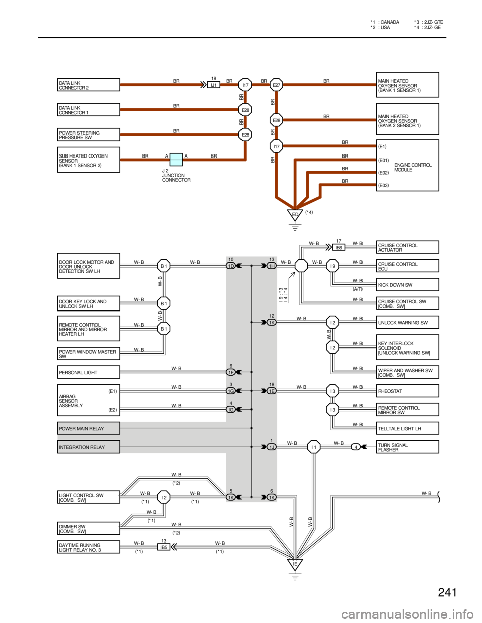
POWER STEERING
PRESSURE SW
DOOR LOCK MOTOR AND
DOOR UNLOCK
DETECTION SW LH
DOOR KEY LOCK AND
UNLOCK SW LH
REMOTE CONTROL
MIRROR AND MIRROR
HEATER LH
POWER WINDOW MASTER
SW
PERSONAL LI GHT
AIRBAG
SENSOR
ASSEMBLY
POWER MAIN RELAY
INTEGRATION RELAY
LIGHT CONTROL SW
[COMB. SW]
DI MME R SW
[COMB. SW]
DAYTIME RUNNING
LI GHT RELAY NO . 3MAIN HEATED
OXYGEN SENSOR
(
BANK 1 SENSOR 1)
MAIN HEATED
OXYGEN SENSOR
(
BANK 2 SENSOR 1)
(
E1)
CRUISE CONTROL
ECU
KI CK DOWN SW
CRUISE CONTROL SW
[C OMB . SW ]
UNLOCK WA RNI NG SW
KEY INTERL OCK
SOLENOI D
[UNLOCK WARNING SW]
WIPER AND WASHER SW
[C OMB . SW ]
RHEOSTAT
RE MOTE CO NT ROL
MIRROR SW
TELLTALE LIGHT LH
TURN SIGNAL
FL AS HER I17 E27
E28
I17
I 9
I 2
I 2
I 3
I 3
I 1 B 1 B 1 B 1IJ118
ED E28
4
IE(
E01)
(
E02)
W- B
W- B
IB513
W- B
(
*1) W- B
(
*1)(
*4) BR BR BR
BR
BR
BR
BR BR
BR
BR
W- B
W- B
W- B
W- B
W- B
W- B
W- B
W- B W- BW- B W- B W- B
W- B W- B W- B W- B W- B W- B W- B
W- B
W- B
W- BBR
BR BR BR W- B W- B
(
E1)
(
E2)W- B
W- B
W- B
W- B W- B DA TA L I NK
CONNECTOR 2
DA TA L I NK
CONNECTOR 1
E NGI NE CONTROL
MODULE
(
A/T) BR
(
E03)
I 2W- B
W- B
W- B(
*2)
(
*1)
(
*1)(
*1)
(
*2) SUB HE ATED OXYGE N
SENSOR
(
BANK 1 SENSOR 2)E28
BR A A BR
J 2
JUNCTION
CONNE CTOR
BR
CRUISE CONTROL
ACTUATOR W- B
IB617
W- B
I 9 : * 3
I 4 : * 4
1H13
1K12
1E18
1J1
1K6 1D10
1F6
1G3
IG4
1K5
241
* 4 : 2JZ- GE *2 : USA * 1 : CANADA * 3 : 2JZ- GTE
Page 1046 of 1807
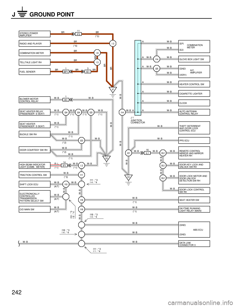
STEREO POWER
AMPLIFIER
RADIO AND PLAY ER
BLOWER MOTOR
CONTROL RELAY
SEAT HEATER RELAY
(
PASSENGER' S SEAT)
SEAT HEATER
(
PASSENGER' S SEAT)
BUCKLE SW RH
DOOR COURTESY SW RH
HIGH BEAM INDICATOR
LIGHT [COMB. METER]
TRACTION CONTROL SW
SHIFT LOCK ECU
ELECTRONICALLY
CONTROLLED
TRANSMISSION
PATTERN SELECT SW
O/D MAIN SWSEAT HEATER SW
DA YTIME RUNNING
LIGHT RELAY (
MAIN) (
EP)
(
GND)
HE ATE R CONTROL SW
CI GARETTE LI GHTER
CL O CK
AU TO AN TENNA
CONTROL RELAY GLOVE BOX LIGHT SW
THEFT DETERRENT
AND DOOR LOCK
CONTROL ECU
PPS ECU
DOOR LOCK CONTROL
SW RH RE MOTE CONTROL
MIRROR AND MIRROR
HE A TE R RH
DOOR LOCK MOTOR AND
DOOR UNL OCK
DE TECTION S W RH DOOR KEY LOCK AND
UNLOCK SW RH IG
IH I24 I24 I23
I23
I 2
I11
I10I21
B 2 B 2 I25
B 2 IL116 IF311
IK11
IF114
I18
I18IF
I14(
E2)
(
VER1)COMBINATION
METER
A/C
AMPLIFIER
W- B
(
*2)W- B
(
*1)
W- B
(
*2)
W- B
(
*1)
W- B
(
*3)
W- B
(
A/T)
W- B
(
*1)
W- B
(
*1) W- B
(
*1)W- B
(
*1)W- B
(
*1) W- B
(
*1)
W- B
(
*1)
W- BW- B
W- B W- BR- L W- B W- B W- B
W- B W- B W- B W- B W- B W- BW- B
W- BW- B
W- B W- B W- B W- B W- B W- B W- B W- B
W- B
W- B BR BR BR
A
A
A
A
A
A A
A
W- B W- BW- B
W- B W- B
W- B W- B W- B
JUNCTION
CONNECTOR J 1
I11 : * 3
I 4 : * 4 (
*1)(
*1) (
*6)
(
GND)
(
GND)ABS ECU
W- BW- B
(
A/T)
(
A/T)
DA TA LI NK
CONNECTOR 3 W- B I 3
I14
BR
W- BW- BW- B (
*5)
COMBINATION METER
TELLTALE LIGHT RH
FUEL SENDERI 8
I 3
IE13
BP11
BR BRBR
BR
BR
BR
BR
W- B
I10 : * 3
I 9 : * 4I18 : * 3
I 4 : * 4
I18 : * 3
I 4 : * 4
I11 : * 3
I 1 : * 4
242
J GROUND POINT
Page 1047 of 1807
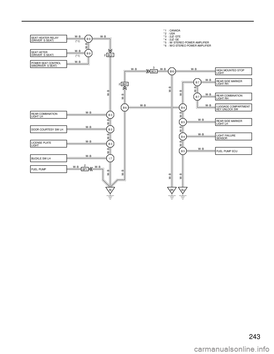
SEAT HEATER RELAY
(
DRIVER' S SEAT)
SEAT HETER
(
DRIVER' S SEAT)
HI GH MOUN TED STOP
LIGHT
REAR COMBINATION
LIGHT LH
DOOR COURTESY SW LH
LICENSE PLATE
LIGHT
BUCKLE SW LH
FUEL PUMPREAR SIDE MARKER
LIGHT RH
RE AR COMBINATION
LIGHT RH
LUGGAGE COMPARTMENT
KEY UNLOCK SW
REAR SIDE MARKER
LIGHT LH
LI GHT FAI LURE
SEN SOR
FU EL PUMP EC U B 9
B 9
B 3
B 3
B 3
I 7B 5 B 4 B 5 B 4B 7 B 7
BI BJ BQ1 2
W- B
W- B
W- B
W- B
W- B W- BW- B W- B W- BW- B W- B W- B W- B
W- B W- B
(
*1)
W- B
(
*1)
W-B W-B W-B W-B W-B
W- B W- B W- B W- B W- B
W- BW- B
BP12* 1 : CANADA
*2 : USA
* 6 : W/ O STEREO POWER AMPLIFIER * 5 : W/ STEREO POWER AMPLIFIER *3 : 2JZ- GTE
*4 : 2JZ- GE
P OWE R SEA T CONTRO L
SW(
DRIVER' S SEAT)
W- B
BK
W- B
B10 BO13
W- B W- B W- B
W- B
B 6 BM1 2
W- B
W- B
243
Page 1048 of 1807
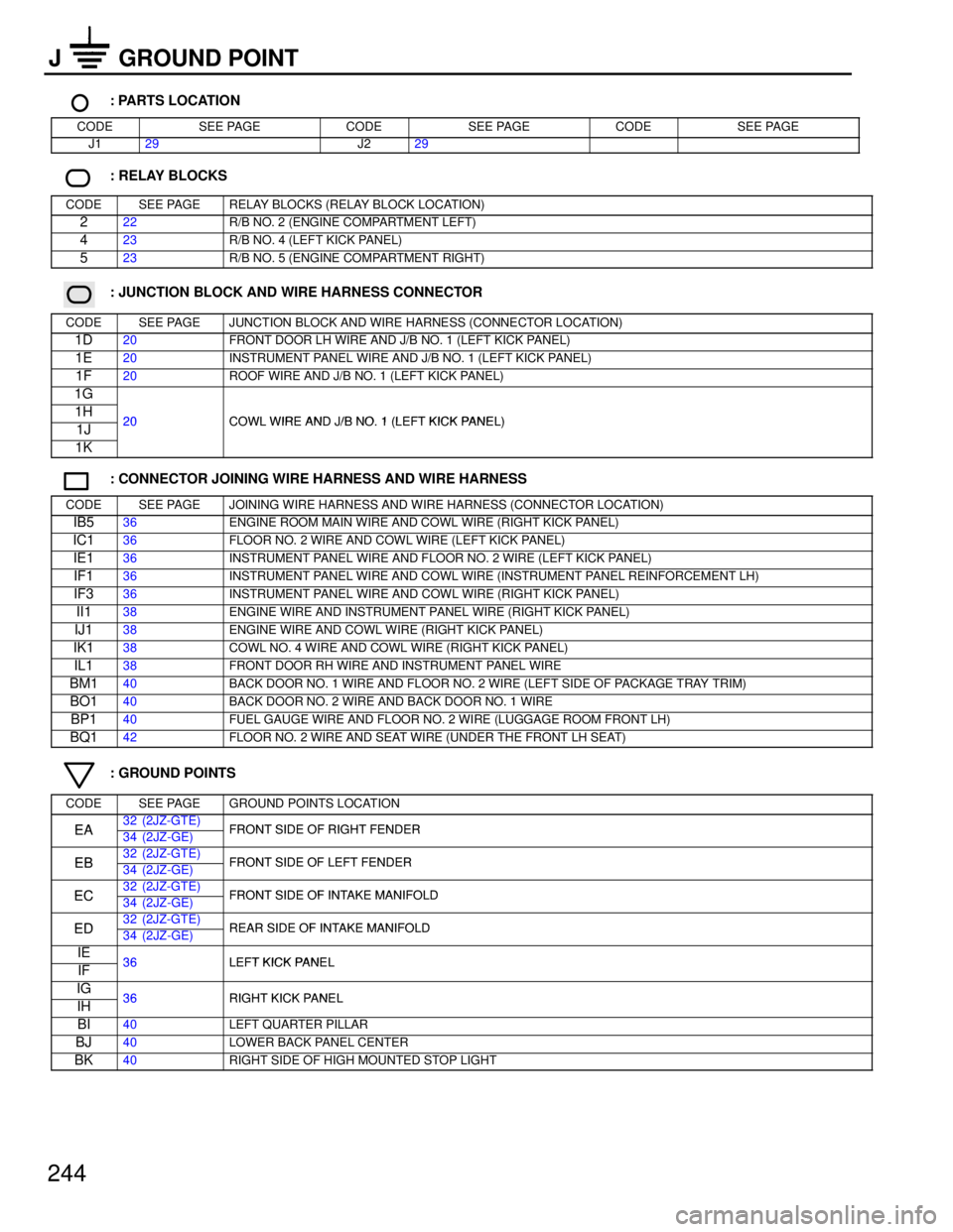
244
J GROUND POINT
: PARTS LOCATION
CODESEE PAGECODESEE PAGECODESEE PAGE
J129J229
: RELAY BLOCKS
CODESEE PAGERELAY BLOCKS (RELAY BLOCK LOCATION)
222R/B NO. 2 (ENGINE COMPARTMENT LEFT)
423R/B NO. 4 (LEFT KICK PANEL)
523R/B NO. 5 (ENGINE COMPARTMENT RIGHT)
: JUNCTION BLOCK AND WIRE HARNESS CONNECTOR
CODESEE PAGEJUNCTION BLOCK AND WIRE HARNESS (CONNECTOR LOCATION)
1D20FRONT DOOR LH WIRE AND J/B NO. 1 (LEFT KICK PANEL)
1E20INSTRUMENT PANEL WIRE AND J/B NO. 1 (LEFT KICK PANEL)
1F20ROOF WIRE AND J/B NO. 1 (LEFT KICK PANEL)
1G
1H20COWL WIRE AND J/B NO 1 (LEFT KICK PANEL)1J20COWL WIRE AND J/B NO. 1 (LEFT KICK PANEL)
1K
: CONNECTOR JOINING WIRE HARNESS AND WIRE HARNESS
CODESEE PAGEJOINING WIRE HARNESS AND WIRE HARNESS (CONNECTOR LOCATION)
IB536ENGINE ROOM MAIN WIRE AND COWL WIRE (RIGHT KICK PANEL)
IC136FLOOR NO. 2 WIRE AND COWL WIRE (LEFT KICK PANEL)
IE136INSTRUMENT PANEL WIRE AND FLOOR NO. 2 WIRE (LEFT KICK PANEL)
IF136INSTRUMENT PANEL WIRE AND COWL WIRE (INSTRUMENT PANEL REINFORCEMENT LH)
IF336INSTRUMENT PANEL WIRE AND COWL WIRE (RIGHT KICK PANEL)
II138ENGINE WIRE AND INSTRUMENT PANEL WIRE (RIGHT KICK PANEL)
IJ138ENGINE WIRE AND COWL WIRE (RIGHT KICK PANEL)
IK138COWL NO. 4 WIRE AND COWL WIRE (RIGHT KICK PANEL)
IL138FRONT DOOR RH WIRE AND INSTRUMENT PANEL WIRE
BM140BACK DOOR NO. 1 WIRE AND FLOOR NO. 2 WIRE (LEFT SIDE OF PACKAGE TRAY TRIM)
BO140BACK DOOR NO. 2 WIRE AND BACK DOOR NO. 1 WIRE
BP140FUEL GAUGE WIRE AND FLOOR NO. 2 WIRE (LUGGAGE ROOM FRONT LH)
BQ142FLOOR NO. 2 WIRE AND SEAT WIRE (UNDER THE FRONT LH SEAT)
: GROUND POINTS
CODESEE PAGEGROUND POINTS LOCATION
EA32 (2JZ-GTE)FRONT SIDE OF RIGHT FENDEREA34 (2JZ-GE)FRONT SIDE OF RIGHT FENDER
EB32 (2JZ-GTE)FRONT SIDE OF LEFT FENDEREB34 (2JZ-GE)FRONT SIDE OF LEFT FENDER
EC32 (2JZ-GTE)FRONT SIDE OF INTAKE MANIFOLDEC34 (2JZ-GE)FRONT SIDE OF INTAKE MANIFOLD
ED32 (2JZ-GTE)REAR SIDE OF INTAKE MANIFOLDED34 (2JZ-GE)REAR SIDE OF INTAKE MANIFOLD
IE36LEFT KICK PANELIF36LEFT KICK PANEL
IG36RIGHT KICK PANELIH36RIGHT KICK PANEL
BI40LEFT QUARTER PILLAR
BJ40LOWER BACK PANEL CENTER
BK40RIGHT SIDE OF HIGH MOUNTED STOP LIGHT
Page 1061 of 1807
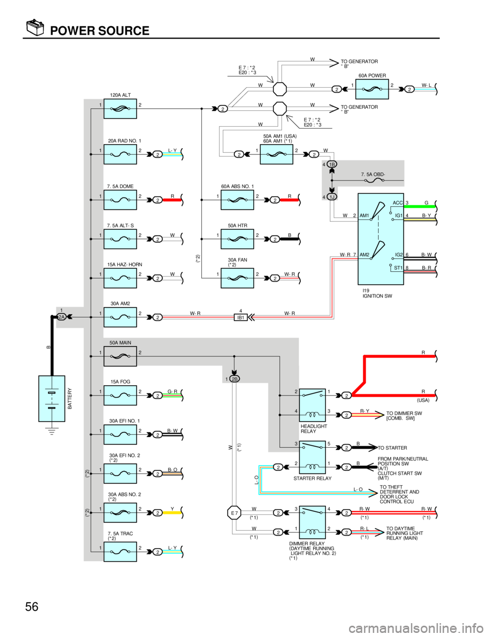
12
12
12
12
12
12
12
12 12
1212
12
12
122
73
4
8 6
E 7
2 2 2
2 2 2 2
2 2 22
2
2
2
2
2
2
2
2
2 2 2 2 IB14
1 3 2 3 4 21
3
5
1
4
2 W- R W- RW
W- R R
B
W- RW
W- L
G
B- Y
B- R B- W
R
R
R- W R- Y
B
B
R- L W W
L- YY B- O B- WG- RW WR L- Y
B
W
(
*1)(
*2) (
*2)(
*2)
(
USA) 120A ALT
20A RAD NO. 1
7. 5A DOME
7. 5A ALT- S
15A HAZ- HORN60A POWER
60A ABS NO. 1
50A HTR
30A FAN
(
*2)
30A EFI NO. 1
30A EFI NO. 2
(
*2)
30A ABS NO. 2
(
*2)
7. 5A TRAC
(
*2)R- WTO DIMMER SW
[COMB. SW]
TO STARTER
FROM PA RK/ NEUTRA L
POSITION SW
(
A/T)
CLUTCH START SW
(
M/T)
TO DAYTIME
RUNNING LIGHT
RELAY (
MAIN) TO GENERATOR
ºBº
IGNITI ON SW I19
HEADLIGHT
RELA Y
STARTER RELAY
DIMMER RELAY
(
DAYTIME RUNNING
LIGHT RELAY NO. 2)
(
*1) 2
1250A AM1 (
US A)
60A AM1 (
*1)
2 2W2
W
TO GENERATOR
ºBº W
WW
(
*1)
(
*1)(
*1)
(
*1)(
*1) W
L- O
L- OTO THEFT
DETERRENT AND
DOOR LOCK
CONTROL ECU 7. 5A OBD- E 7 : * 2
E2 0 : * 3 E 7 : * 2
E20 : * 3
AM2 AM1ACC
IG1
ST1IG2
1J 41B 4
1230A AM22A1
1250A MAIN
15A FOG2B 1
BATTE RY
56
POWER SOURCE