Page 70 of 1807
 Do not heat to more than 60 °C (140 °F). (Temperature
is limited not to damage the components.)")
V07469
HEAT METHOD: When the problem seems to occur when the suspect area is heated. 2
NOTICE:
(1) Do not heat to more than 60 °C (140 °F). (Temperature
is limited not to damage the components.)
(2) Do not apply heat directly to parts in the ECU.
3 WATER SPRINKLING METHOD:
NOTICE:
(1) Never sprinkle water directly into the engine
compartment, but indirectly change the temperature and
humidity by applying water spray onto the radiator front
surface.
(2) Never apply water directly onto the electronic
components.
4 OTHER: When a malfunction seems to occur when electrical load is excessive.When the malfunction seems to occur on a rainy day or in a
high-humidity condition. Heat the component that is the likely cause of the malfunction
with a hair dryer or similar object. Check to see if the malfunction
occurs.
Sprinkle water onto the vehicle and check to see if the malfunc-
tion occurs.
Turn on all electrical loads including the heater blower, head
lights, rear window defogger, etc. and check to see if the mal-
function occurs.ON (Service hint)
If a vehicle is subject to water leakage, the leaked water may
contaminate the ECU. When testing a vehicle with a water leak-
age problem, special caution must be taken.
Malfunc-
tion
- INTRODUCTIONHOW TO TROUBLESHOOT ECU CONTROLLED
SYSTEMSIN-23
23 Author�: Date�:
1997 SUPRA (RM502U)
Page 103 of 1807

22SUPRAÐOUTLINE OF NEW FEATURES
SUPRA
OUTLINE NEW FEATURES
The Supra, which represents Toyota's advanced automotive technology, has earned a reputation as a truly luxurious
sports car. The following changes have been made for the 1997 model year.
1. Model Line±Up
�The JZA80L±ALPVZA model has been discontinued.
�The JZA80L±ALFVZA and JZA80L±AJFVZA models have been added.
2. Exterior Design
�The multi±reflector type headlights are adopted.
�The design of the turn signal light, front bumper and rear combination light has been changed.
3. Interior Equipment
The front seats have been changed from the separate±headrest type seats of the '96 model to the integrated headrest
type seats without changing their basic design.
4. 2JZ±GTE Engine
An aluminum radiator core is adopted for weight reduction.
5. Differential
�A differential gear ratio has been changed on he 2JZ±GE engine model.
�A helical gear type torque±sensing LSD is available as an option on the 2JZ±GE engine model and 2JZ±GTE engine
with automatic transmission model.
6. Drive Shaft
An outboard joint of drive shaft has been changed from cross±groove type CVJ (Constant±Velocity Joint) to Rzeppa
type CVJ on the 2JZ±GE engine model.
7. Brakes
�A master cylinder diameter has been changed on the 2JZ±GTE engine model.
�An ABS has been changed to the 2±position solenoid valve type actuator.
Page 117 of 1807
AC0Q2-01
Z18473
Pressure Switch
ReceiverRadiator
Fan Relay
No. 1
Compressor
Radiator
Fan Relay
No. 2Junction Block No. 2
� Magnetic Clutch Relay
� Reater Main Relay
Ambient Temperature
Sensor
Air Conditioning Amplifier
Solar Sensor
Room Temperature
SensorAir Conditioning
Control Assembly
Evaporator
Expansion Valve
Water Valve
Heater Radiaor
Air Outlet ServomotorAir Inlet
Servomotor
Blower Motor
Blower Motor
Control Relay
Evaporator Temperature Sensor
Air Mix Servomotor
Engine Coolant Temperature Sensor AC-14
- AIR CONDITIONINGAIR CONDITIONING SYSTEM
2162 Author�: Date�:
1997 SUPRA (RM502U)
LOCATION
Page 123 of 1807
N11671
Defroster Nozzle
Water Valve CoverPlate
Water Valve
Heater Radiator
A/C Unit
Block Joint
Blower Motor
Control Relay
Blower Motor
Lower CaseEvaporator
Expansion
Valve Air Inlet
Servomotor
Evaporator Temperature
Sensor Heater Air Duct
Evaporator CoverVent Air DuctEngine Coolant
Temperature
SensorAir Outlet
ServomotorAir Mix
Servomotor AC-24
- AIR CONDITIONINGAIR CONDITIONING UNIT
2172 Author�: Date�:
1997 SUPRA (RM502U)
Page 124 of 1807
AC0QC-01
N08378
I03519
- AIR CONDITIONINGAIR CONDITIONING UNIT
AC-25
2173 Author�: Date�:
1997 SUPRA (RM502U)
REMOVAL
1. DISCHARGE REFRIGERANT FROM REFRIGERANT
SYSTEM
HINT:
At the time of installation, please refer to the following item.
Evacuate air from refrigeration system.
Charge system with the refrigerant and inspect for leakage of
refrigerant.
Specified amount: 700 ± 50 g (24.96 ± 1.76 oz.)
2. DRAIN ENGINE COOLANT FROM RADIATOR
HINT:
It is not necessary to drain out all coolant.
3. REMOVE THESE PARTS:
(a) Engine wire harness bracket mounting bolt
(b) Brake tube bracket mounting bolts
4. DISCONNECT WATER HOSE FROM HEATER RADIA-
TOR PIPES
(a) Using priers, grip the claw of the hose clip and slide the
clip along the hose.
(b) Disconnect the water hoses from heater radiator pipes.
5. REMOVE INSULATOR RETAINER
Remove the 2 bolts and the insulator retainer.
Page 127 of 1807
N08403
AC-28
- AIR CONDITIONINGAIR CONDITIONING UNIT
2176 Author�: Date�:
1997 SUPRA (RM502U)
6. REMOVE HEATER RADIATOR AND WATER VALVE
(a) Remove the 2 screws and the plate.
(b) Remove the 2 screws and the clamp.
(c) Remove the 3 screws.
(d) Pull out the heater radiator with the water valve.
(e) Remove the 2 screws and water valve from the heater ra-
diator.
7. REMOVE HEATER AIR DUCT
Remove the 2 screws and the defroster air duct.
8. REMOVE AIR VENT DUCT
(a) Disconnect the control link.
(b) Remove the 2 screws and the vent air duct.
9. REMOVE ENGINE COOLANT TEMPERATURE SEN-
SOR
(a) Disconnect the connector.
(b) After pulling off the clamp, pull out the sensor.
10. REMOVE AIR OUTLET SERVOMOTOR
(a) Disconnect the connector.
(b) Remove the 3 screws and the air outlet servomotor.
Page 135 of 1807

REMOVAL
1. DISCHARGE REFRIGERANT FROM REFRIGERATION
SYSTEM
HINT:
At the time of installation, please")
AC0QN-01
N08732
N16963
AC-40
- AIR CONDITIONINGRECEIVER
2188 Author�: Date�:
1997 SUPRA (RM502U)
REMOVAL
1. DISCHARGE REFRIGERANT FROM REFRIGERATION
SYSTEM
HINT:
At the time of installation, please refer to the following item.
Evacuate air from refrigeration system.
Charge system with refrigerant and inspect for leakage of refrig-
erant.
Specified amount: 700 ± 50 g (24.96 ± 1.76 oz.)
2. REMOVE FRONT BUMPER (See page BO-4)
3. REMOVE RADIATOR SUPPORT UPPER SEAL
Remove the 12 clips and radiator support upper seal.
4. REMOVE LIQUID TUBES FROM RECEIVER
Remove the 2 bolts and both tubes from the receiver.
Torque: 5.4 N´m (55 kgf´cm, 48 in.´lbf)
NOTICE:
Cap the open fittings immediately to keep moisture or dirt
out of the system.
HINT:
At the time of installation, please refer to the following item.
Lubricate 2 new O-rings with compressor oil and install the
tube.
5. REMOVE RECEIVER
Remove the holder bolt and pull the receiver downward from
the receiver holder.
HINT:
At the time of installation, please refer to the following item.
If receiver is replaced, add compressor oil to receiver.
Add 10 cc (0.34 fl.oz.)
Compressor oil: ND-OIL 8 or equivalent
6. REMOVE RECEIVER HOLDER
Remove the screw and holder.
Page 137 of 1807
N08731
N08730
N08726
N08727
AC-44
- AIR CONDITIONINGCONDENSER
2192 Author�: Date�:
1997 SUPRA (RM502U)
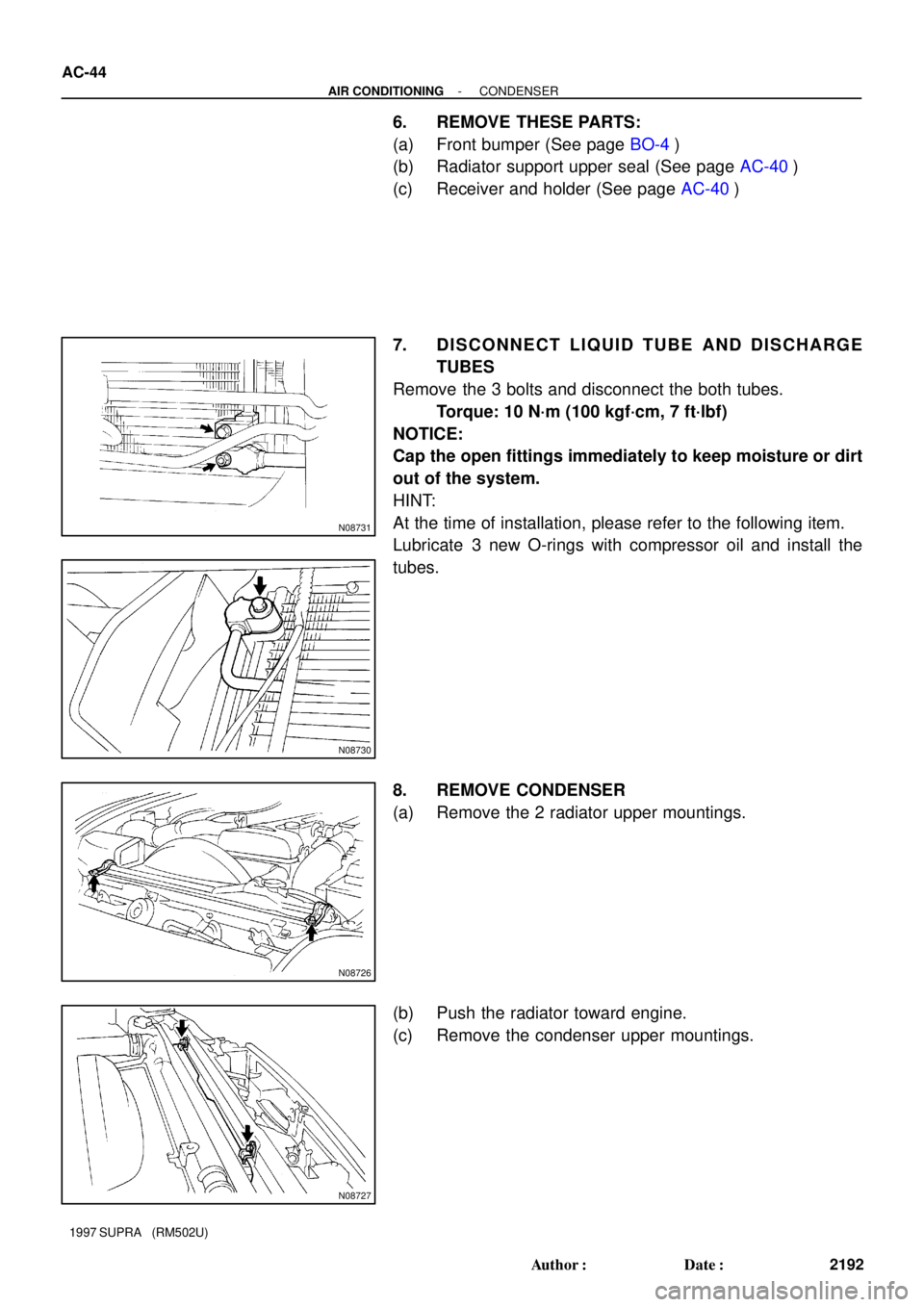
6. REMOVE THESE PARTS:
(a) Front bumper (See page BO-4)
(b) Radiator support upper seal (See page AC-40)
(c) Receiver and holder (See page AC-40)
7. DISCONNECT LIQUID TUBE AND DISCHARGE
TUBES
Remove the 3 bolts and disconnect the both tubes.
Torque: 10 N´m (100 kgf´cm, 7 ft´lbf)
NOTICE:
Cap the open fittings immediately to keep moisture or dirt
out of the system.
HINT:
At the time of installation, please refer to the following item.
Lubricate 3 new O-rings with compressor oil and install the
tubes.
8. REMOVE CONDENSER
(a) Remove the 2 radiator upper mountings.
(b) Push the radiator toward engine.
(c) Remove the condenser upper mountings.