Page 597 of 3342
1) Set the vehicle on lift arms.
2) Open front hood fully and support with stay.
G2M0341
3) Release fuel pressure.
(1) Disconnect fuel tank connector.
(2) Start the engine, and run until it stalls.
(3) After the engine stalls, crank it for five seconds
more.
(4) Turn ignition switch to“OFF”.
G6M0095
4) Disconnect battery cables and remove battery from
vehicle.
B2M0015A
5) Drain coolant.
Set container under the vehicle, and remove drain cock
from radiator.
G2M0263
6) Remove cooling system.
(1) Disconnect radiator fan motor connector.
(2) Disconnect radiator outlet hose from thermostat
cover.
9
2-11SERVICE PROCEDURE
2. Engine
Page 608 of 3342

B: INSTALLATION
1. Install engine to transmission.
2. Tighten bolts which hold upper side of transmission to engine.
3. Remove lifting device and wire rope.
4. Remove garage jack.
5. Install pitching stopper.
AT model
6. Install torque converter onto drive plate.
7. Install canister and bracket.
8. Install power steering pump on bracket.
9. Tighten nuts which hold lower side of transmission to engine.
10. Tighten nuts which install front cushion rubber onto cross-
member.
11. Install front exhaust pipe and center exhaust pipe.
12. Connect hoses, connectors and cables.
13. Install air intake system.
�Air intake duct
�Air cleaner element and upper cover.
With A/C
14. Install A/C pressure hoses.
15. Install cooling system.
16. Install battery onto the vehicle, and connect cables.
17. Fill coolant.
18. Check ATF level, and connect if necessary. [AT]
19. Correct power steering oil, and bleed air.
20. Remove front hood stay, and close front hood.
21. Take off the vehicle from lift arms.
�
�
�
�
�
�
�
�
�
�
�
�
20
2-11SERVICE PROCEDURE
2. Engine
Page 613 of 3342
B2M0307A
15) Install cooling system.
(1) Attach radiator mounting cushions to body.
G2M0220
(2) Install radiator while fitting radiator pins to cush-
ions.
B2M0320
(3) Install radiator brackets and tighten bolts.
Tightening torque:
13.7±1.5 N⋅m (1.4±0.15 kg-m, 10.1±1.1 ft-lb)
G2M0263
(4) Connect radiator fan motor connector.
G2M0267
(5) Connect radiator inlet hose.
25
2-11SERVICE PROCEDURE
2. Engine
Page 709 of 3342

Automatic
transmissionOil pumpType Variable-capacity type vane pump
Driving method Driven by engine
Number of vanes 9 pieces
Hydraulic
controlTy p eElectronic/hydraulic control
[Four forward speed changes by electrical signals of car speed
and accelerator (throttle) opening]
Fluid Dexron II or Dexron III type Automatic transmission fluid
Fluid
capacity2200 cc 7.9�(8.4 US qt, 7.0 Imp qt)
2500 cc 9.5�(10.0 US qt, 8.4 Imp qt)
LubricationLubrication system Forced feed lubrication with oil pump
Oil Automatic transmission fluid (above mentioned.)
Cooling Cooling system Liquid-cooled cooler incorporated in radiator
HarnessInhibitor switch 12 poles
Transmission harnessFWD ... 11 poles
AWD ... 13 poles
TransferTransfer clutch Hydraulic multi-plate clutch
Clutch number of transfer clutch Drive plate & driven plate 5
Control method Electronic, hydraulic type
LubricantThe same Automatic Transmission Fluid used in automatic
transmission.
1st reduction gear ratio 1.000 (53/53)
Final
reductionFinal gear
ratioFront driveFWD 3.900 (39/10)
AWD2200 cc 4.111 (37/9)
2500 cc 4.444 (40/9)
Speedometer gear ratio2200 cc & LSi 0.83 (19/23)
GT 0.80 (20/25)
OUTBACK 0.76 (19/25)
Lubrication oilAPI, GL-5
Oil capacity Front drive 1.2�(1.3 US qt, 1.1 Imp qt)
ATF cooling
systemRadiation capacity 1.651 kW (1,420 kcal/h, 5,635 BTU/h)
3
3-2SPECIFICATIONS AND SERVICE DATA
1. Automatic Transmission and Differential
Page 1280 of 3342
7. CLEARANCE TABLE (LHD MODEL)
CAUTION:
This table lists various clearances that must be cor-
rectly adjusted to ensure normal vehicle driving with-
out interfering noise, or any other faults.
LocationMinimum
allowance
mm (in)LocationMinimum
allowance
mm (in)
�
1Crossmember—Pipe5 (0.20)�6Exhaust pipe—Pipe15 (0.59)
�
2DOJ—Shaft or joint14 (0.55)�7Exhaust pipe—Gearbox bolt15 (0.59)
�
3DOJ—Valve housing11 (0.43)�8Side frame—Hose A and B15 (0.59)
�
4Pipe—Pipe
2 (0.08)�
9Cruise control pump—Hose A and B15 (0.59)
Pipe—Crossmember�
10Pipe portion of hose A—Pipe portion of hose B1.5
(0.059)
�
5Stabilizer—Pipe5 (0.20)�11AT cooling hose—Joint20 (0.79)
B4M0565A
96
4-3DIAGNOSTICS
1. Power Steering
Page 1455 of 3342
4.885 kW
(4,200 kcal/h, 16,666 BTU/h)
RefrigerantHFC-134a (CH
2FCF3)")
1. Air Conditioning System
A: SPECIFICATIONS
Item Specifications
Type of air conditionerReheat air-mix type
Cooling capacity (IMACA)4.885 kW
(4,200 kcal/h, 16,666 BTU/h)
RefrigerantHFC-134a (CH
2FCF3)
[0.55 — 0.65 kg
(1.21 — 1.43 lb)]
CompressorType 5-vane rotary, fix volume (DKV-14D)
Discharge 140 cm
3(8.54 cu in)/rev
Max. permissible speed 7,000 rpm
Magnet clutchTy p eDry, single-disc type
Power consumption 45 W
Type of belt V-Ribbed 4 PK
Pulley dia. (effective dia.) 125 mm (4.92 in)
Pulley ratio1.064
CondenserType Corrugated fin (Multi-flow)
Core face area 0.215 m
2(2.31 sq ft)
Core thickness 19 mm (0.75 in)
Radiation area 4.7 m
2(51 sq ft)
Receiver drier Effective inner capacity 290 cm3(17.70 cu in)
Expansion valve TypeInternal equalizing
EvaporatorTy p eA�-laminate
Dimensions (W x H x T)74 x 224 x 235 mm
(2.91 x 8.82 x 9.25 in)
Blower fanFan typeSirocco fan
Outer diameter x width 150 x 75 mm (5.91 x 2.95 in)
Power consumption 230 W at 12 V
Condenser fan
(Sub fan)Motor typeMagnet
Power consumption 120 W at 12 V
Fan outer diameter 320 mm (12.60 in)
Radiator fan
(Main fan)Motor typeMagnet
Power consumption 120 W at 12 V
Fan outer diameter 320 mm (12.60 in)
Idling speed with
F.I.C.D. in operationMPFI model 850±100 rpm (700±100 rpm “D” range in AT model)
Dual switch
(Pressure switch)
High-pressure line
B4M0755A
Compressor relief valve
blow-out pressure
B4M0084A
Thermo control
amplifier working
temperature
(Evaporator outlet air)
B4M0756A
2
4-7SPECIFICATIONS
1. Air Conditioning System
Page 1458 of 3342
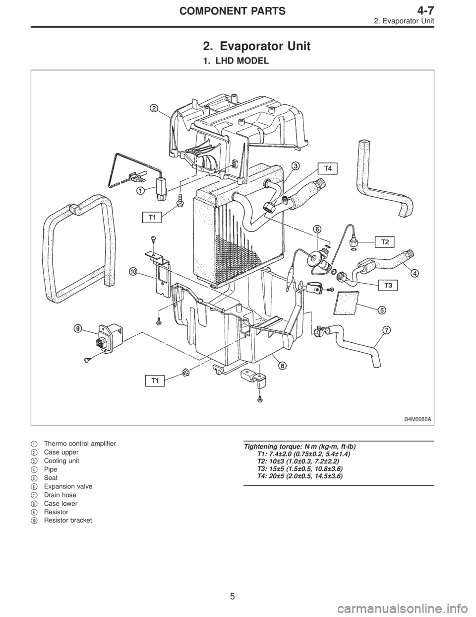
2. Evaporator Unit
1. LHD MODEL
B4M0086A
�1Thermo control amplifier
�
2Case upper
�
3Cooling unit
�
4Pipe
�
5Seat
�
6Expansion valve
�
7Drain hose
�
8Case lower
�
9Resistor
�
10Resistor bracket
Tightening torque: N⋅m (kg-m, ft-lb)
T1: 7.4±2.0 (0.75±0.2, 5.4±1.4)
T2: 10±3 (1.0±0.3, 7.2±2.2)
T3: 15±5 (1.5±0.5, 10.8±3.6)
T4: 20±5 (2.0±0.5, 14.5±3.6)
5
4-7COMPONENT PARTS
2. Evaporator Unit
Page 1459 of 3342
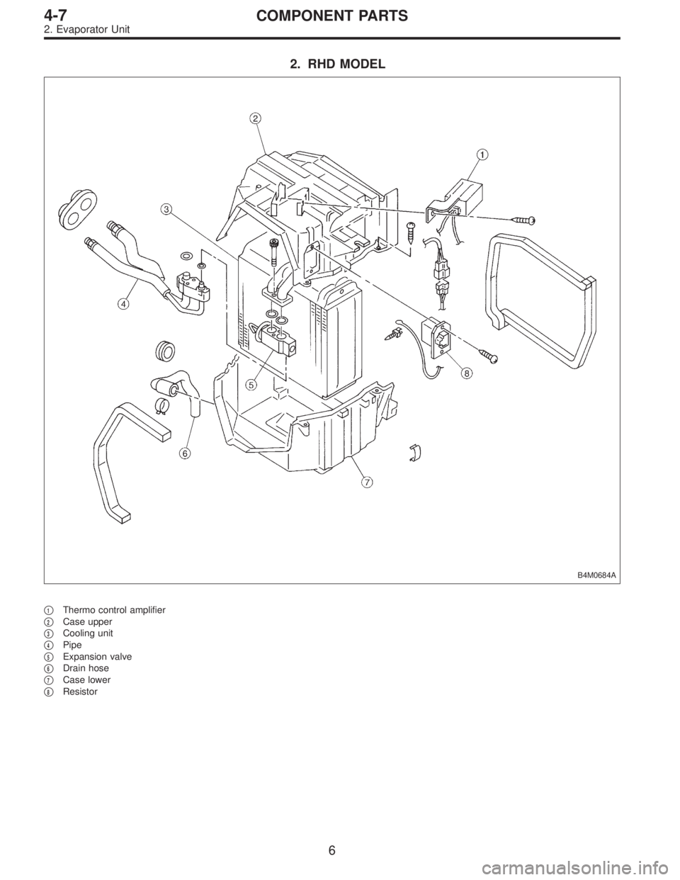
2. RHD MODEL
B4M0684A
�1Thermo control amplifier
�
2Case upper
�
3Cooling unit
�
4Pipe
�
5Expansion valve
�
6Drain hose
�
7Case lower
�
8Resistor
6
4-7COMPONENT PARTS
2. Evaporator Unit
 Set the vehicle on lift arms.
2) Open front hood fully and support with stay.
G2M0341
3) Release fuel pressure.
(1) Disconnect fuel tank connector.
(2) Start the engine, and run until it stalls.
(3")
 Install cooling system.
(1) Attach radiator mounting cushions to body.
G2M0220
(2) Install radiator while fitting radiator pins to cush-
ions.
B2M0320
(3) Install radiator brackets and ti")

CAUTION:
This table lists various clearances that must be cor-
rectly adjusted to ensure normal vehicle driving with-
out interfering noise, or any other faults.
Locatio")