Page 147 of 363

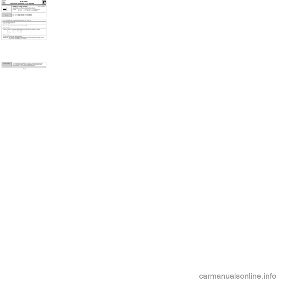
Connect the bornier in place of the computer and check the insulation and continuity of the line :
Computer 17 2 Coil
Computer 35 1 Coil
Repair if necessary.
JSA051.0
INJECTION
Fault finding - Interpretation of XR25 bargraphs17
D7F 710
engine -
35 tracks
Turn the engine, switch the ignition on and erase the computer memory using
G0**. Try to start the engine. Switch the ignition on, then deal with the other
faults. Remember to carry out a status and parameter check.AFTER REPAIR
Bargraph 16 LH side illuminatedFiche n° 27 side 1/2
COMPUTER MPA CONNECTION CIRCUIT
XR25 aid:*16 = XX.CO=> CO or CC- line 17 or 35 of the computer
*16 = XX.CC=> CC+ line 17 or 35 of the computer
16
XX = 14 => Cylinder 1 or 4 line 35 of the computer
XX = 23 =
> Cylinder 2 or 3 line 17 of the computerNOTES
Check the resistance of the coil.
Replace the coil if necessary.
Check the + after ignition feed to the coil concerned on track 3.
Repair if necessary.
The fault persists! Replace the injection computer.
IMPORTANT: The computer has probably been damaged by an electric shock. The cause of the damage
must be found before fitting a new computer.
Check the hygiene of the anti-interference condenser on track 4 of the coil.
17-102
Page 160 of 363

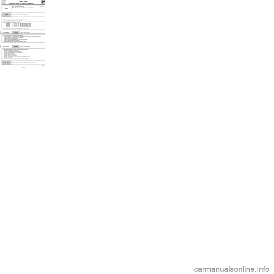
Check the insulation and continuity of the line:
Computer 11 D Idle speed regulation motor
Computer 12 A Idle speed regulation motor
Computer 28 B Idle speed regulation motor
Computer 29 C Idle speed regulation motor
Repair if necessary and continue fault finding using the value for # 06.
JSA051.0
INJECTION
Fault finding - Status and parameter interpretation17
D7F 710
engine -
35 tracks
AFTER REPAIRStart the status and parameter check again from the beginning.
DIAG 7
IDLE SPEED REGULATIONFiche n° 27
XR25 aid:Engine speed , Minimum < # 06 < Maximum
No fault bargraphs should be illuminated.NOTES
Check the resistance of the idle speed regulation stepping motor.
Replace the idle speed regulation valve if necessary.
# 06 < MinimumThe idle speed is too lowNOTES
Idle speed regulation is not maintaining the idle speed.
- Clean the air supply circuit (throttle body, idle regulation valve), since it is probably contaminated.
- Check the engine oil level (too high ---
> splashing).
- Check and ensure correct fuel pressure.
- Using the OPTIMA 5800 station, check the engine compression.
- Check the valve clearances and the timing.
If all these points are correct, replace the idle regulation motor.
# 06 > MaximumThe idle speed is too highNOTES
An air leak may be affecting the idle speed regulation programming.
- Check the connections on the manifold.
- Check the hygiene of the pipes on the manifold.
- Check the pneumatically controlled solenoid valves.
- Check the manifold gaskets.
- Check the throttle body gaskets.
- Check the sealing of the brake servo.
- Check the restrictions are present in the oil vapour rebreathing circuit.
- Check the fuel pressure.
If all these points are correct, replace the idle speed regulation motor.
17-115
Page 171 of 363
JSA051.0
INJECTION
Fault finding - Status and parameter interpretation17
D7F 710
engine -
35 tracks
AFTER REPAIRStart the status and parameter check again from the beginning.
DIAG 17
Fiche n° 27
POWER ASSISTED STEERING PRESSOSTAT
XR25 aid:None
No fault bargraphs should be illuminated.NOTES
Check the correct operation of the power assisted steering (oil level, ...).
Check the power assisted steering pressostat is correctly connected.
Check the insulation and continuity of the line for track 7 on the injection computer.
Repair if necessary.
If all these points are correct, replace the power assisted steering pressostat.
17-126
Page 175 of 363
JSA051.0
INJECTION
Fault finding - Fault charts
17
D7F 710
engine -
35 tracks
AFTER REPAIR
Chart 2IDLE SPEED FAULTS
Only refer to this customer complaint after a complete check using the XR25.NOTES
Erase the computer memory using G0** and carry out a road test.
Check there is fuel present
(fuel gauge faulty).
Check the fuel is of the correct type.
Check the hosesCheck no hoses are pinched
(especially after a removal operation).
Check the oil levelUse the dipstick to check if the
oil level is too high.
Check the fuel
Check the flywheelConnect the OPTIMA 5800 station to carry out the flywheel test
and follow the instructions.
Check the idle speed
regulation valveTap gently to release the valve.
Check the manifoldCheck the condition of the manifold gaskets.
Check the injectorsCheck, after removal, that the injectors do not drip.
A
17-130
Page 177 of 363
JSA051.0
INJECTION
Fault finding - Fault charts
17
D7F 710
engine -
35 tracks
AFTER REPAIRErase the computer memory using G0** and carry out a road test.
Chart 3BEHAVIOUR WHILE DRIVING
Only refer to this customer complaint after a complete check using the XR25.NOTES
Check the air filter is not deformed.
Check the fuel
Check there is fuel present
(fuel gauge faulty).
Check the fuel is of the correct type.
Check the hosesCheck no hoses are pinched
(especially after a removal operation).
Check the air filter
Check the oil levelUse the dipstick to check if the
oil level is too high.
Check the condition of the manifold gaskets.Check the inlet
manifold
Check the exhaust manifold is not leaking.Check the exhaust
manifold
Check, after removal, that the injectors do not drip.Check the injectors
Check the throttle body is not contaminated.Check the throttle body
Check the brake servo is not leaking (noise).Check the brake servo
A
17-132
Page 179 of 363
JSA051.0
INJECTION
Fault finding -Aid
17
D7F 710
engine -
35 tracks
For further details, refer to section 12
Injector resistance = 14.5 Ω
Idle regulation stepping
motor resistance : A - D= 100 Ω
B - C = 100 Ω
Canister bleed valve resistance = 35 Ω
Ignition coil resistance : Primary = 1-4 ; 1-3 ; 2-3 ; 2-4 = 1.5 Ω
3-4 = 0.6 Ω
Secondary = 8 kΩ
Oxygen sensor heating resistance = 3 to 15 Ω
Throttle potentiometer resistance : no load A-B = 1300 Ωfull load A-B = 1300 Ω
A-C = 1360 ΩA-C= 2350 Ω
B-C = 2300 ΩB-C = 1260 Ω
Flywheel signal resistance = 220 Ω
Fuel pressure = 3 bars ignition on/ 2.5 bars at idle speed
Value for: CO = 0.3 % maximum
HC = 100 ppm maximum
CO2 = 14.5 % minimum
Lambda = 0.97 < λ < 1.03
Sensor resistance
Temperature in °C 0 20 40 80 90
Air temperature sensor
Resistance in ohms5000
to
70001700
to
3300500
to
1550--
Coolant temperature sensor
Resistance in ohms6700
to
80002600
to
30001100
to
1300270
to
300200
to
215
17-134
Page 217 of 363

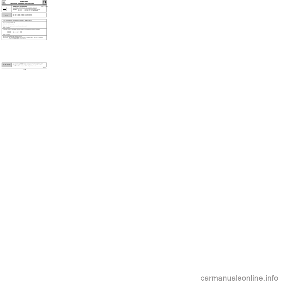
Connect the bornier in place of the computer and check the insulation and continuity of the line :
Computer 29 2 Coil
Computer 28 1 Coil
Repair if necessary.
JSA052.0
INJECTION
Fault finding - Interpretation of XR25 bargraphs17
D7F 710
engine -
55 tracks
Turn the engine, switch the ignition on and erase the computer memory using
G0**. Try to start the engine. Switch the ignition on, then deal with the other
faults. Remember to carry out a status and parameter check.AFTER REPAIR
Bargraph 16 LH side illuminated Fiche n° 27 side 1
COMPUTER MPA CONNECTION CIRCUIT
XR25 aid:*16 = XX.CO=> CO or CC- line 28 or 29 of the computer
*16 = XX.CC=> CC+ line 28 or 29 of the computer
16
XX = 14 => Cylinder 1 or 4 line 28 of the computer
XX = 23 =
> Cylinder 2 or 3 line 29 of the computerNOTES
Check the resistance of the coil.
Replace the coil if necessary.
Check the + after ignition feed to the coil concerned on track 3.
Repair if necessary.
The fault persists! Replace the injection computer.
IMPORTANT: The computer has probably been damaged by an electric shock. The cause of the damage
must be found before fitting a new computer.
Check the hygiene of the anti-interference condenser on track 4 of the coil.
17-174
Page 230 of 363

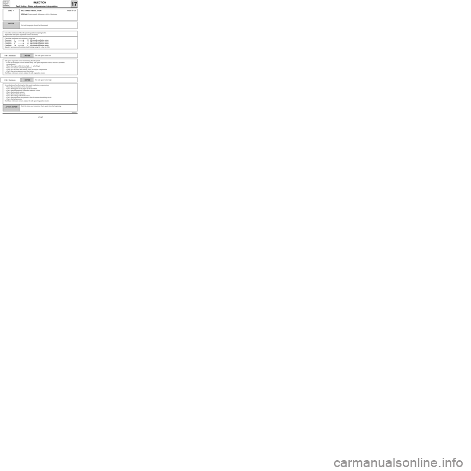
Check the insulation and continuity of the line:
Computer 8 D Idle speed regulation motor
Computer 35 A Idle speed regulation motor
Computer 9 B Idle speed regulation motor
Computer 36 C Idle speed regulation motor
Repair if necessary and continue fault finding using the value for # 06.
JSA052.0
INJECTION
Fault finding - Status and parameter interpretation17
D7F 710
engine -
55 tracks
AFTER REPAIRStart the status and parameter check again from the beginning.
DIAG 7IDLE SPEED REGULATION Fiche n° 27
XR25 aid: Engine speed , Minimum < # 06 < Maximum
No fault bargraphs should be illuminated.
NOTES
Check the resistance of the idle speed regulation stepping motor.
Replace the idle speed regulation valve if necessary.
# 06 < MinimumThe idle speed is too lowNOTES
Idle speed regulation is not maintaining the idle speed.
- Clean the air supply circuit (throttle body, idle speed regulation valve), since it is probably
contaminated.
- Check the engine oil level (too high ---> splashing).
- Check and ensure correct fuel pressure.
- Using the OPTIMA 5800 station, check the engine compression.
- Check the valve clearances and the timing.
If all these points are correct, replace the idle regulation motor.
# 06 > MaximumThe idle speed is too highNOTES
An air leak may be affecting the idle speed regulation programming.
- Check the connections on the manifold.
- Check the hygiene of the pipes on the manifold.
- Check the pneumatically controlled solenoid valves.
- Check the manifold gaskets.
- Check the throttle body seals.
- Check the sealing of the brake servo.
- Check the restrictions are present in the oil vapour rebreathing circuit.
- Check the fuel pressure.
If all these points are correct, replace the idle speed regulation motor.
17-187