Page 141 of 208

STARTING - CHARGING
Alternator
16
OPERATION - FAULT FINDING
These vehicles are equipped with alternators with
internal ventilation and integral regulator, also
with a warning light on the instrument panel
which has the following functions :
- when the ignition is switched on, the light illu-
minates
- when the engine is started the light extin-
guishes,
- if the light illuminates whilst the engine is
running there is a "charging "fault.
LOOKING FOR FAULTS
The warning light does not illuminate when the
ignition is switched on.
Check:
- all electrical connections are good.
- the bulb has not blown. (Earth the circuit and
the bulb should illuminate).
The warning light illuminates when the engine is
running.
This indicates a charging fault which could be
caused by :
- the alternator drive belt being broken or the
charging wiring being cut,
- internal alternator damage (rotor, stator,
diodes or brush),
- a regulator fault,
- excess voltage.The customer complains of a lack of charge and
the warning light is operating correctly.
If the regulated voltage is less than 13.5 V, check
the alternator. The fault could be caused by :
- a diode which has been damaged,
- a phase which is cut,
- contaminated or worn tracks.
Checking the voltage
Connect a voltmeter across the battery terminals
and read the battery voltage.
Start the engine and increase the engine speed
until the needle registers a stable regulated
voltage.
This voltage should be between 13.5 V and 14.8 V.
Connect as many consumers as possible, the
regulated voltage should be between 13.5 V and
14.8 V.
IMPORTANT: if arc welding work is to be carried
out on the vehicle, the battery and regulator
must be disconnected.
16-2
Page 142 of 208

STARTING - CHARGING
Alternator
16
OPTIMA 5800 Diagnostic station
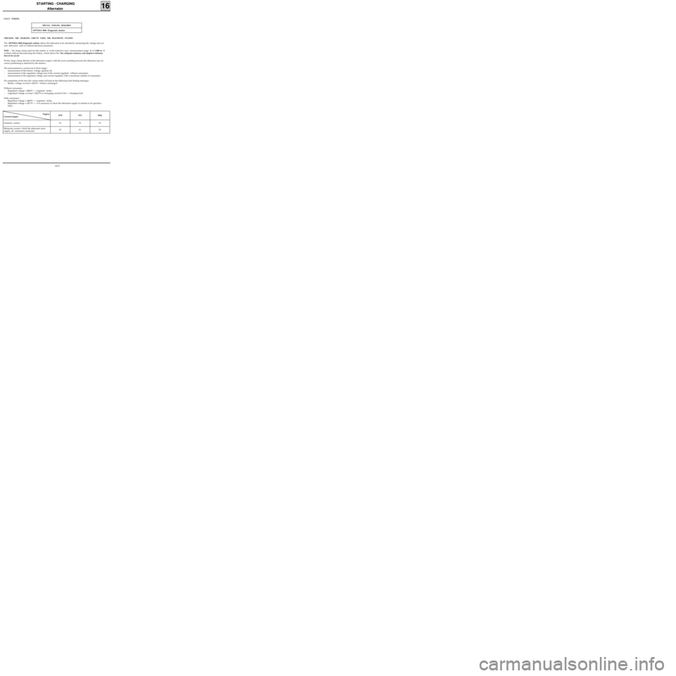
CHECKING THE CHARGING CIRCUIT USING THE DIAGNOSTIC STATION
The OPTIMA 5800 diagnostic station allows the alternator to be checked by measuring the voltage and cur-
rent delivered , with or without electrical consumers .
NOTE : the Amps clamp used for this station is of the inductive type (measurement range: 0 to 1 000 A). It
is fitted without disconnecting the battery, which allows the the computer memory and adaptive informa-
tion to be saved.
Fit the Amps clamp directly at the alternator output, with the arrow pointing towards the alternator (any in-
correct positioning is detected by the station).
The measurement is carried out in three stages :
- measurement of the battery voltage, ignition off,
- measurement of the regulated voltage and of the current supplied, without consumers,
- measurement of the regulated voltage and current supplied, with a maximum number of consumers.
On completion of the test, the values noted will lead to the following fault finding messages :
- Battery voltage, no load < 12.3 V = battery uncharged.
Without consumers :
- Regulated voltage > 14,8 V = > regulator faulty ,
- (regulated voltage, no load < 13.2 V) or (charging current< 2 A) = >charging fault.
With consumers :
- Regulated voltage > 14.8 V = > regulator faulty,
- Regulated voltage < 12.7 V = > it is necessary to check the alternator supply in relation to its specifica-
tions :
Engine
Current (amps)D7F E7J F8Q
Nominal current 70 75 75
Minimum current which the alternator must
supply, all consumers connected 53 51 55
FAULT FINDING
SPECIAL TOOLING REQUIRED
16-3
Page 147 of 208

STARTING - CHARGING
Starter motor
16
OPTIMA 5800 Diagnostic station
CHECKING THE STARTER MOTOR USING THE DIAGNOSTIC STATION
Checking of the starter motor is carried out using the OPTIMA 5800, by measuring the battery voltage and
the current absorbed in the engine starting phase. The following operation faults may be highlighted :
- a fault in the battery ( the voltage falls during the starting phase),
- locking of the starter motor (the current absorbed is too high),
- a fault in the engine starter gear (the current absorbed is too low).
In order to carry out the measurement, it is necessary to stop the vehicle from starting :
- for D7F and E7J engines : disconnect the engine speed sensor (located on the clutch housing ,
- for
F8Q engines : disconnect the pump electrical solenoid and isolate the terminal.
NOTE :
- an open circuit on the engine speed sensor or the ignition creates a fault memorised by the injection
computer, this fault must then be erased from the memory using the
XR25 (see "Injection" section),
- if the engine is fitted with an immobiliser, it is sufficient to lock the doors using the remote control.
FAULT FINDING
SPECIAL TOOLING REQUIRED
16-8
Page 151 of 208

IGNITION
Semi-static ignition
17
PRESENTATION
The system comprises:
- the injection computer (the ignition power
stage is integrated into the computer),
- two dual output coils, (for the
D7F engine,
these are moulded into one),
- four spark plugs,
- an anti-interference condenser (4).
DESCRIPTION - OPERATING PRINCIPLE
COMPUTER
The injection computer (120), depending on the
information received from various sensors, but
principally depending on the engine speed and
load, determines:
- the number of degrees of advance to be used
and consequently the ignition point,
- which cylinders are at TDC and consequently
the ignition coil to be operated.
The spark is created at the two cylinders at TDC by
cutting the earth to the coil concerned.
COILS (1)
There are two coils. They are of the dual output
type (they cannot be separated in the
D7F en-
gine ).
They are controlled separately by the computer.
They create two sparks simultaneously.
Both coils are connected to an anti-interference
condenser.
99931-1R2
D7F Engine
E7J Engine
13242R
Special features of the E7J engine
The coil at (2) has a black electrical connector. It
creates a spark simultaneously at cylinders 1 and
4. It is controlled by track 28 of the injection
computer.
The coil at (3) has a grey electrical connector . It
creates a spark simultaneously at cylinders 2 and
3. It is controlled by track 29 of the injection
computer.
17-1
Page 152 of 208
IGNITION
Semi-static ignition
17
Test to be made
between tracksResistance
1 - 2 1.5 Ω
1 - 3 1 Ω
1 - 4 1 Ω
2 - 3 1 Ω
2 - 4 1 Ω
3 - 4 0.6 Ω
HT - HT8 kΩ
D7F Engine
Electrical connector
Track Allocation
1coil control for cylinders
1-4
2coil control for cylinders
3-2
3 +after ignition
4+anti-interference
condenser
Test to be made
between tracksResistance
1 - 2 0.5 Ω
1 - 3 1 Ω
2 - 3 1 Ω
HT - HT10 kΩ
Track Allocation
1+anti-interference
condenser
2 +after ignition
3coil control by
computer
D7F Engine
Electrical connector
17-2
Page 153 of 208
IGNITION
Spark plugs
17
Engine Make Type
D7F
EYQUEM
NGK
RFC 50 LZ 2E
BKR 5EK
E7JEYQUEM
CHAMPIONRFC 52 LS
RC 10 PYC
Flat skirt with seal
Gap: 0.9 mm
Tightening torque : 2.5 to 3 daN.m
D7F Engine
To disconnect the spark plug leads, use the tool (3), which is integrated to the plastic cover (4) on the cylin-
der head.
99940R
99894R1
D7F/E7J
Engines
NOTE : to remove the spark plugs, use the tool kit, Ele. 1382.
17-3
Page 154 of 208
INJECTION
General
17
SPECIAL NOTES FOR MULTIPOINT INJECTION
• 35 track SAGEM or MAGNETI MARELLI computer for vehicles without options.
• 55 track SAGEM computer ,
SAFIR or MAGNETI MARELLI type for versions with air conditioning.
•Semi-sequential multipoint injection. Injectors controlled two by two (injectors for cylinders 1 and 4 fol-
lowed by injectors for cylinders 2 and 3).
•Semi-static ignition with dual single unit coils.
•Canister bleed solenoid valve controlled by RCO signal.
•Computer configuration depending on gearbox type (manual gearbox or automatic transmission).
•The maximum engine speed permitted is 6 200 rpm.
•Idle speed correction depending on :
- battery voltage,
- air conditioning
- power assisted steering pressostat.
•Injection warning light on instrument panel not operational.
•Use fault finding fiche n° 27. D7F Engine
FITTING A 2ND GENERATION ENGINE IMMOBILISER REQUIRES A SPECIAL PROCEDURE FOR REPLACING THE
COMPUTER.
17-4
Page 155 of 208
INJECTION
General
17
SPECIAL NOTES FOR MULTIPOINT INJECTION
• 55 track SIEMENS FENIX 5 computer.
•Semi-sequential multipoint injection. Injectors are controlled two by two (injectors for cylinders 1 and 4
followed by cylinders 2 and 3).
•Semi-static ignition with dual coils.
•Canister bleed solenoid controlled by RCO signal.
•Computer configuration depending on gearbox type (manual gearbox or automatic transmission)
•Idle speed correction depending on :
- air conditioning,
- power assisted steering pressostat,
- battery voltage.
•Injection warning light on instrument panel operational.
•Use fault finding fiche n° 27.
•Maximum speed :
-6 200 rpm if 1st , 2nd or 3rd gears
-6 000 rpm if 4th,or 5th gears. E7J Engine
FITTING A 2ND GENERATION ENGINE IMMOBILISER REQUIRES A SPECIAL PROCEDURE FOR REPLACING THE
COMPUTER.
17-5