Page 159 of 208
INJECTION
Location of components
17
H Locking relay
K Fuel pump relay
3 Oxygen sensor
(tightening torque : 5 daN.m)
12993R
1 Coil
19 Anti-interference condenser
99931-1R1
12839S
17 Power assisted steering pressostat
13050R
D7F Engine
17-9
Page 162 of 208
INJECTION
Location of components
17
K Fan assembly relay (for versions with air
conditioning)
L Fuel pump relay
M Fan assembly relay (for versions without air
conditioning) slow speed fan assembly (with
air conditioning) 15 Power assisted steering pressostat
13241R
12839S
E7J engine
17-12
Page 191 of 208
Mot. 1199-01 Exhaust pipe cutting tool
Mot. 1265
Mot. 1265-01
FUEL TANK
Fuel tank
19
IMPORTANT : during all the fuel tank removal
and refitting operations, refrain from smoking
and be sure not to handle incandescent objects in
the vicinity of the working area.
DRAINING THE FUEL TANK (Petrol version)
Remove the pump-sender unit assembly steel ac-
cess cover.
Remove the clip which shows if the assembly has
been pushed in (if fitted).
Disconnect the quick release union at (1), tool
Mot. 1265.
EQUIPMENT REQUIRED
INTAIRCO pneumatic siphoning pump, for
petrol or diesel tank draining system (see EQUIPMENT
catalogue).
SPECIAL TOOLING REQUIRED
97163R2
Attach to the outlet at (A), a pipe long enough to
be placed into a container outside the vehicle .
NOTE : Alternatively, an INTAIRCO pneumatic si-
phoning pump may be used (see
EQUIPMENT ca-
talogue). Sender unit- pump nut 7
TIGHTENING TORQUES (in daN.m)
Pliers for removing quick release
fuel unions
19-17
Page 192 of 208
FUEL TANK
Fuel tank
19
In the engine compartment, disconnect the fuel
pump relay at (K) , which is located in the engine
connection unit.
12839S
DRAINING THE FUEL TANK ( Diesel version)
Since Diesel versions are not fitted with an electri-
cal fuel pump, a manual pump must be used to
drain the tank.
For example, the
INTAIRCO pneumatic siphoning
pump is suitable for this operation (see
EQUIPMENT catalogue),
Shunt tracks 3 and 5 and let the fuel flow until it
runs out in intermittent jets.
Disconnect the shunt.
Reconnect the relay.
Disconnect the battery.Remove the pump-sender unit steel access cover.
Remove the clip which shows if the assembly has
been pushed in (if fitted).
Disconnect the quick release union at (1), tool
Mot. 1265.
99641S
97163R2
Connect the pneumatic pump rubber tube to the
outlet union at (A).
Drain the tank.
19-18
Page 203 of 208
FUEL TANK
Sender unit
19
In petrol versions, the pump and sender unit can-
not be separated.
In diesel versions, there is no pump immersed in
the tank, and there is only a sender unit.
For the removal of the sender unit, please refer to
subsections "Tank", "Pump-sender unit".
Checking the sender unit
Check for a variation in resistance by moving the
float.
NOTE : all the above values are given merely as
an indication.
IndicationValue between terminals
A1 and B1 (in Ω)
4/4 7 maximum
3/4 54.5 ± 7
1/2 98 ± 10
1/4 155 ± 16
Low fuel level 300 ± 20
19-29
Page 204 of 208

Mot. 1264 Wrench for removing
Mot. 1264-01 pump-sender unit assembly nut
Mot. 1265 Pliers for removing
Mot. 1265-01 quick release unions
FUEL TANK
Pump- sender unit
19
SPECIAL TOOLING REQUIRED
IMPORTANT :
During all operations on the fuel tank or on the
fuel supply circuit , it is vital :
- to refrain from smoking and handling incan-
descent objects in the vicinity of the working
area,
- to avoid fuel projections, due to the residual
pressure present in the pipes during removal .
REMOVAL
To remove the pump-sender unit assembly, it is
not necessary to remove the tank, as it is accessi-
ble through the inside of the vehicle. To do this :
- disconnect the battery,
- lift the rear bench seat ,
- remove the steel access cover,
- remove the electrical connection at (1),
- remove the clips at (2).
97163R5
Nut for pump - sender unit assembly 7
TIGHTENING TORQUES (in daN.m)Disconnect, using tool Mot. 1265 or Mot. 1265-
01:
- the fuel supply pipe (3) (which is marked by a
green quick release union),
- the fuel return pipe (4) (marked by a red quick
release union and by an arrow (B)).
96420R1
19-30
Page 205 of 208

FUEL TANK
Pump- sender unit
19
REFITTING
Check that the seal is not deformed, and replace it
if necessary.
Position the pump-sender unit assembly
(ensuring that the arrow at (F) is placed in the
longitudinal axis of the vehicle pointing to the
rear).
Position the nut and tighten it to the torque of
3.5 daN.m.
Fit the fuel pipes (it is not necessary to use the
pliers Mot. 1265 or Mot. 1265-01).
Refit the safety clips at (2).
Reconnect the electrical connection.
Refit the steel cover.
ALLOCATION OF CONNECTOR TRACKS
TRACK ALLOCATION
A1 Earth
A2 Fuel minimum level warning light
B1 Sender unit information to instrument
panel
B2 Not used
C1 pump
C2 pump
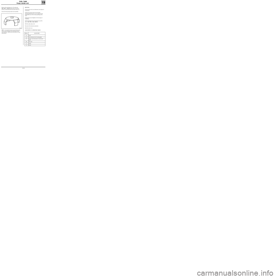
Remove the mounting nut at (5) using tool
Mot. 1264 or 1264-01 (release the nut, remove
the tool, hand slacken the nut, then remove it).
Extract the fuel pump-sender unit assembly.
99367S
NOTE : if several hours have to pass between the
removal and refitting of the fuel pump-sender
unit assembly, refit the nut on the tank, to avoid
deforming it.
19-31
Page:
< prev 1-8 9-16 17-24