Page 154 of 208
INJECTION
General
17
SPECIAL NOTES FOR MULTIPOINT INJECTION
• 35 track SAGEM or MAGNETI MARELLI computer for vehicles without options.
• 55 track SAGEM computer ,
SAFIR or MAGNETI MARELLI type for versions with air conditioning.
•Semi-sequential multipoint injection. Injectors controlled two by two (injectors for cylinders 1 and 4 fol-
lowed by injectors for cylinders 2 and 3).
•Semi-static ignition with dual single unit coils.
•Canister bleed solenoid valve controlled by RCO signal.
•Computer configuration depending on gearbox type (manual gearbox or automatic transmission).
•The maximum engine speed permitted is 6 200 rpm.
•Idle speed correction depending on :
- battery voltage,
- air conditioning
- power assisted steering pressostat.
•Injection warning light on instrument panel not operational.
•Use fault finding fiche n° 27. D7F Engine
FITTING A 2ND GENERATION ENGINE IMMOBILISER REQUIRES A SPECIAL PROCEDURE FOR REPLACING THE
COMPUTER.
17-4
Page 155 of 208
INJECTION
General
17
SPECIAL NOTES FOR MULTIPOINT INJECTION
• 55 track SIEMENS FENIX 5 computer.
•Semi-sequential multipoint injection. Injectors are controlled two by two (injectors for cylinders 1 and 4
followed by cylinders 2 and 3).
•Semi-static ignition with dual coils.
•Canister bleed solenoid controlled by RCO signal.
•Computer configuration depending on gearbox type (manual gearbox or automatic transmission)
•Idle speed correction depending on :
- air conditioning,
- power assisted steering pressostat,
- battery voltage.
•Injection warning light on instrument panel operational.
•Use fault finding fiche n° 27.
•Maximum speed :
-6 200 rpm if 1st , 2nd or 3rd gears
-6 000 rpm if 4th,or 5th gears. E7J Engine
FITTING A 2ND GENERATION ENGINE IMMOBILISER REQUIRES A SPECIAL PROCEDURE FOR REPLACING THE
COMPUTER.
17-5
Page 164 of 208

INJECTION
Injection fault warning light
17
PRINCIPLE FOR ILLUMINATION OF INJECTION FAULT WARNING LIGHT ON INSTRUMENT PANEL
• Vehicles not equipped with the immobiliser function:
When the ignition is switched on, the warning light illuminates constantly for 3 seconds , then extin-
guishes.
• Vehicles with immobiliser function deactivated:
When the ignition is switched on, the injection warning light illuminates constantly for 3 seconds and
then extinguishes.
When the doors are unlocked, the red immobiliser light, which was previously flashing, extin-
guishes.When ignition is switched on, it illuminates for 3 seconds , then extinguishes.
• Vehicles with immobiliser function activated:
When the ignition is switched on, the computer does not recognise the code, and stops the engine from
starting. The injection warning light remains illuminated for 3 seconds and then extinguishes.
Before the ignition is switched on, the red immobiliser light flashes. On switching the ignition on, it
flashes more rapidly.
If a fault is detected in the immobiliser system whilst the engine is running, the injection warning light
flashes in the engine speed range between idle speed and 1 500 rpm approximately .
• Fault in a component of the injection system
The warning light is illuminated if a fault has been detected in:
- the pressure sensor,
- the vehicle speed,
- the throttle potentiometer,
- the idle speed regulation stepping motor.
17-14
Page 165 of 208
INJECTION
Immobiliser function
17
This vehicle is fitted with a 2nd generation immobiliser system.
REPLACING THE INJECTION COMPUTER
All computers are supplied uncoded, but are capable of being programmed with a code.
When replacing the computer, the vehicle code must be programmed in and then a check must be made to
ensure that the immobiliser system is operational.
To do this, it is sufficient to carry out the following operations:
- turn the ignition on for a few seconds and turn it off again,
- remove the key to guarantee the immobiliser function.
CHECKING THE IMMOBILISER FUNCTION
Remove the key from the ignition switch. After 10 seconds the red immobiliser warning light will flash.
For special notes on testing an injection computer (test part), refer to section 82: "Immobiliser".
17-15
Page 205 of 208

FUEL TANK
Pump- sender unit
19
REFITTING
Check that the seal is not deformed, and replace it
if necessary.
Position the pump-sender unit assembly
(ensuring that the arrow at (F) is placed in the
longitudinal axis of the vehicle pointing to the
rear).
Position the nut and tighten it to the torque of
3.5 daN.m.
Fit the fuel pipes (it is not necessary to use the
pliers Mot. 1265 or Mot. 1265-01).
Refit the safety clips at (2).
Reconnect the electrical connection.
Refit the steel cover.
ALLOCATION OF CONNECTOR TRACKS
TRACK ALLOCATION
A1 Earth
A2 Fuel minimum level warning light
B1 Sender unit information to instrument
panel
B2 Not used
C1 pump
C2 pump
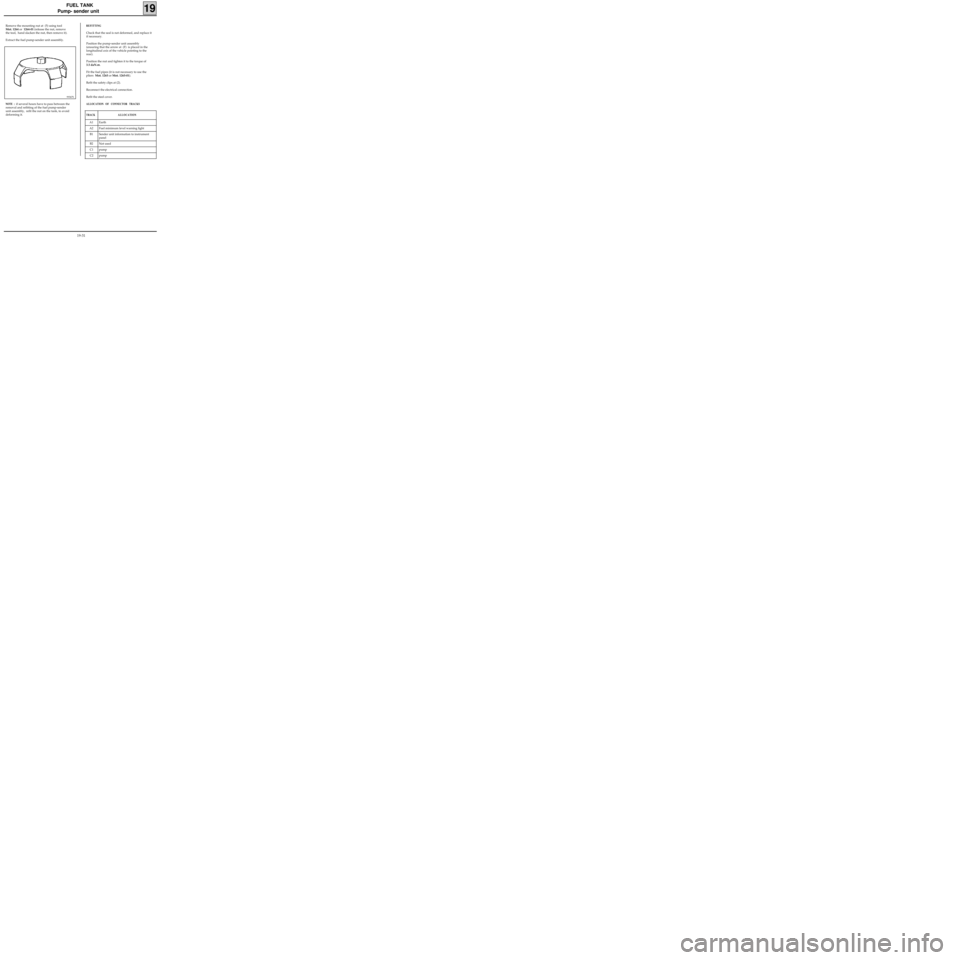
Remove the mounting nut at (5) using tool
Mot. 1264 or 1264-01 (release the nut, remove
the tool, hand slacken the nut, then remove it).
Extract the fuel pump-sender unit assembly.
99367S
NOTE : if several hours have to pass between the
removal and refitting of the fuel pump-sender
unit assembly, refit the nut on the tank, to avoid
deforming it.
19-31