Page 87 of 208

FUEL SUPPLY
Pump flow
13
Petrol
engines
96093R2
SPECIAL TOOLING REQUIRED
Mot. 1265 Pliers for removing quick release
unions
EQUIPMENT REQUIRED
2 000 ml measuring cylinder
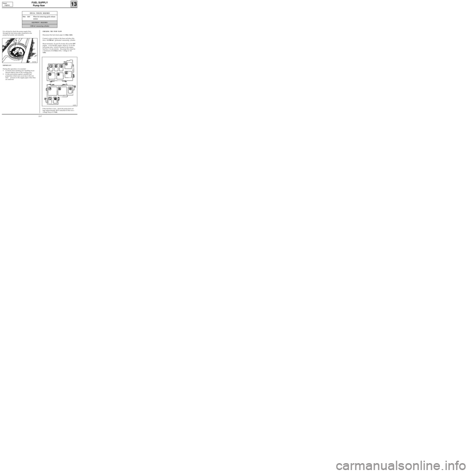
It is advised to check the pump supply flow
through the fuel return pipe connected to the
pump-fuel sender unit assembly.
IMPORTANT
During this operation, it is essential :
• to refrain from smoking and handling incan-
descent objects close to the working area,
• to take precautions against possible fuel
projections which may occur due to the resi-
dual pressure in the supply pipes when they
are removed.
CHECKING THE PUMP FLOW
Disconnect the fuel return pipe (1) (Mot. 1265).
Connect a piece of pipe to the hose and place this
into a 0-2 000 ml graduated measuring cylinder.
Shunt terminals (3) and (5) of relay (K) on the DF7
engine, or for the
E7J engine shunt at (L) on the
fuel pump relay (which is located in the engine
fuse box ). In one minute, the pump flow must be
a minimum of 1.3 litres with a voltage of 12
volts.
If the fuel flow is low, check the pump feed vol-
tage (approximately 10 % reduction in flow for a
voltage drop of 1 Volt)
12839S
13-7
Page 88 of 208
FUEL SUPPLY
Fuel pressure
13
CHECKING THE FUEL PRESSURE
SPECIAL TOOLING REQUIRED
Mot. 1311-01 Fuel pressure test kit (with a pressure
gauge 0; + 10 bar tool kit)
Mot. 1311-05 Junction tool (for union K)
Mot. 1311-06 Tool for removing fuel supply unions
IMPORTANT : during the opening of the fuel cir-
cuit , be sure to use a cloth to avoid possible pro-
jections of fuel due to the residual pressure.
Disconnect the fuel supply pipe using the tool
Mot. 1311-06 with the largest section (see method
described in section 13 "Injector gallery").
Connect tool Mot. 1311-05 to the injector gallery,
then reconnect the fuel supply pipe to the tool
itself.
99375R
99934R1
99939S
DF7 Engine
13-8
Page 89 of 208
FUEL SUPPLY
Fuel pressure
13
Connect pressure gauge 0 ; 10 bars along with
the flexible hose, Mot. 1311-01.
Shunt terminals (3) and (5) on the pump relay (K) ,
which is situated in the engine fuse box.
99938-1R
12839S
The pressure must be 3 bars ± 0,2.
By applying a pressure of 500 mbars to the
pressure regulator, a fuel pressure of 2.5 bars ±
0.2 should be obtained. DF7 Engine
13-9
Page 90 of 208
FUEL SUPPLY
Fuel pressure
13
CHECKING THE FUEL PRESSURE
SPECIAL TOOLING REQUIRED
Mot. 1311-01 Fuel pressure test kit (with a pressure
gauge 0; + 10 bar tool kit)
Mot. 1311-05 Junction tool (for union J)
IMPORTANT : during the opening of the fuel cir-
cuit , be sure to use a cloth to avoid possible pro-
jections of fuel due to the residual pressure.
Disconnect the fuel supply pipe.
Fit tool Mot. 1311-04 on the injector gallery, then
reconnect the fuel supply pipe to the tool itself.
13244-1R
EF7 Engine
Connect the pressure gauge 0; + 10 bars with
the flexible pipe Mot. 1311-01.
99376R
13-10
Page 91 of 208
FUEL SUPPLY
Fuel pressure
13E7J Engine
Shunt terminals (3) and(5) of the fuel pump relay
(L) located in the engine fuse box .
12839S
The pressure must be 3 bars ± 0.2.
By applying a pressure of 500 mbars to the
pressure regulator, a fuel pressure of 2.5 bars ±
0.2 should be obtained.
13-11
Page 120 of 208

DIESEL EQUIPMENT
Pump
13
Remove :
- the fuel supply pipe (A),
- the fuel return pipe (B),
- the pump connector (C),
- the accelerator cable (D),
- the vacuum pipe (E) connected to the fast
idle speed LDA,
- the high pressure wiring loom using tool Mot.
1383,
10578R
- the rear support mounting bolt.
12869R
Fit tool Mot. 1200 or Mot. 1317 , for retaining the
pump pulley.
12410R
Inserting a torx screwdriver in the gaps of the
RAM pulley, slacken:
- the three bolts mounting the pump
- the central nut securing the pump shaft to the
RAM pulley.
Slacken the central nut and all three of the bolts
mounting the pump until they are completely
free.
Extract the pump.
REFITTING
Clean the pump shaft very thoroughly, using sol-
vent to eliminate all trace of grease.
Refit the pump.
Tighten the three bolts mounting the pump .
Pretighten the central nut of the pump to 2
daN.m.
IMPORTANT : it is vital to carry out a pretighte-
ning operation before the final tightening; tigh-
ten the central pump nut to a torque of 4.5
daN.m.
Carry out the timing operations (see "Pump -
Timing").
For all other operations, refitting is the reverse of
removal.
13-40
Page 130 of 208

ANTIPOLLUTION
Fuel vapour rebreathing
14
CONDITION FOR BLEEDING THE CANISTER ( D7F
engine)
• Coolant temperature greater than+ 15 °C
•Air temperature greater than +10 °C.
• No load position not recognised (if there is a
fault in the throttle potentiometer sensor, the
condition of no load position not recognised is
replaced by an engine speed condition
R > 1500 rpm.).
It is possible to visualise the cyclical opening ratio
for the canister bleed solenoid using the
XR25
and #23. The solenoid is closed if #23 = 0.7 %
CONDITION FOR BLEEDING THE CANISTER (E7J
engine)
During richness regulation
Coolant temperature greater than 50°C.
Air temperature greater than 15°C.
No load position not recognised (if there is a fault
in the throttle potentiometer sensor, the
condition of no load position not recognised is
replaced by an engine speed condition
R > 1500 rpm.).
Outside richness regulation
•Coolant temperature greater than 50°C.
•Air temperature greater than 15°C.
•Full load position recognised (function of
engine speed and manifold pressure).
If there is a fault in the oxygen sensor, bleeding is
permitted outside of no load conditions.
It is possible to visualise the cyclical opening ratio
for the canister bleed solenoid using the
XR25
and #23. The solenoid is closed if #23 = 0.7 %
(minimum value).
14-4
Page 131 of 208

ANTIPOLLUTION
Fuel vapour rebreathing
14
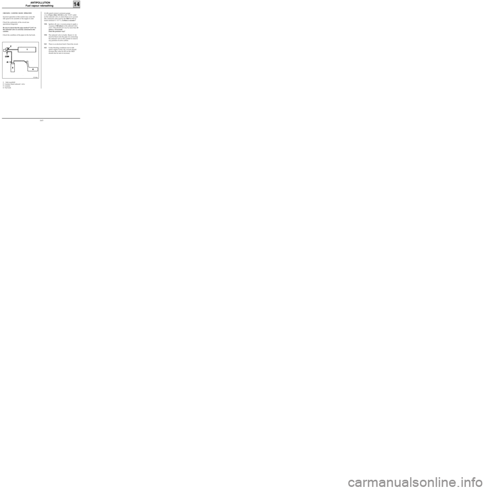
CHECKING CANISTER BLEED OPERATION
Incorrect operation of the system may cause the
idle speed to be unstable or the engine to stall.
Check the conformity of the circuit (see
operational diagrams)
Be sure to check that the pipe marked "CAN" on
the solenoid valve is correctly connected to the
canister.
Check the condition of the pipes to the fuel tank.
97393R6
1Inlet manifold
2Canister bleed solenoid valve
3Canister
4Fuel tankAt idle speed connect a pressure gauge
(- 3 ; +3 bars) (Mot. 1311-01) to the "CAN" outlet
on the solenoid valve, to check there is no vacuum
(the command value read by the
XR25 for #23 re-
mains minimal X = 0.7 % ). Is there a vacuum ?
YESIgnition off, use a vacuum pump to apply a
vacuum of 500 mbars to the solenoid valve
at (C). This should not vary by more than 10
mbars in 30 seconds.
Does the pressure vary?
YESThe solenoid valve is faulty. Renew it. Air
must be blown into the pipe (A) connecting
the solenoid valve to the canister to remove
any particles of active carbon.
NOThere is an electrical fault. Check the circuit.
NOUnder bleeding conditions (not at idle
speed, engine warm), the vacuum should
increase (the value for #23 on the XR25
should also be seen to increase).
14-5