Page 36 of 105

REAR AXLE
Half suspension arms, tubular rear axle
REFITTING
Ensure the bearing races or the needle bearings
are in perfect condition, otherwise replace them
(see section "Bushes, tubular rear axle").
The needle bearings are greased for life and do
not require further lubrication.
NOTE : new suspension arms are supplied by the
Parts Department fitted with bearing races or
needle bearings (depending on side).
Fit the two half suspension arms together until
dimension (B) is obtained.
NOTE : dimension (B) corresponds to the distance
between the same two mounting points for the
anti-roll bar on the suspension arms. It is therefore
possible to obtain this dimension by positioning
the anti-roll bar in its location and checking the
mounting bolts can be correctly positioned.
Ensure the fitting direction is observed.
Refitting is then the reverse of removal.
NOTE : if the half suspension arm is renewed,
bond the brake backing plate mounting bolts
with
Loctite FRENBLOC.
Bleed the brake circuit.
Adjust the handbrake control (see section 37).
33
TIGHTENING TORQUES (in daN.m)
Bearing mounting nut 11
Anti-roll bar mounting bolt 5.5
Wheel bolt 9
Shock absorber base bolt 8.5
REMOVAL
Put the vehicle on a two post lift, remove:
- the anti-roll bar,
- the lower shock absorber mounting,
- the secondary handbrake cable, disconnecting
at the central adjuster under the vehicle,
- the brake pipe,
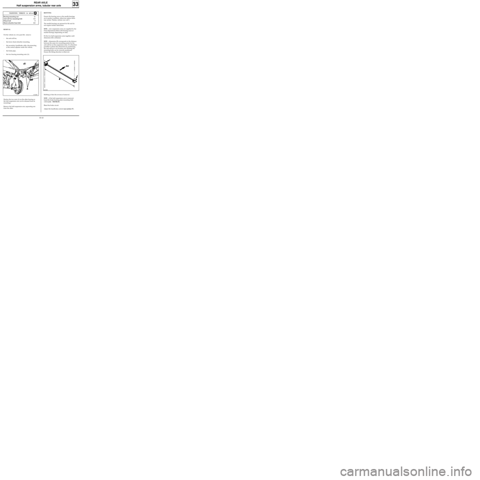
- the two bearing mounting nuts (A).
Slacken the two nuts (A) on the other bearing so
the half suspension arm can be released from its
mountings.
Remove the half suspension arm, separating one
from the other.
13132R1
86320R
33-10
Page 46 of 105
REAR AXLE
Suspension arm bearings
This operation is carried out after removing the
rear arms and the suspension bars.
REMOVAL
Totally immerse the bearing in brake fluid to
soften the rubber bush.
Using a two or three claw extractor, remove the
external part of the bearing by tearing off the
rubber.
Saw through the inner ring taking care not to
scratch in the tube of the arm.
REFITTING
The bearing is fitted in the arm on the press,
ensuring the correct alignment is observed and
the clearance between the bearing and the arm is
correct.
Alignment
Observe dimension "X" between the bearing
pressure face and the stub axle shaft:
X = 156 mm ± 3.5
TUBULAR REAR
AXLE
33
DI3303
85909S
75362S
DI3310
33-20
Page 69 of 105

MECHANICAL ELEMENT CONTROLS
Master cylinder
37
Hydraulic pipe unions 1.7
Mounting nut on brake servo 1.8
REMOVAL
Disconnect the battery.
Disconnect the brake fluid level detector
connector.
Remove the injection computer (depending on
version).
Release the PAS reservoir and move it to the side,
towards the engine.
Drain and remove, by pulling up, the brake fluid
reservoir (take care to catch the fluid which will
run out).
Remove:
- the pipes and note their positions,
- the two mounting nuts on the brake servo.
REFITTING
Refitting is the reverse of removal.
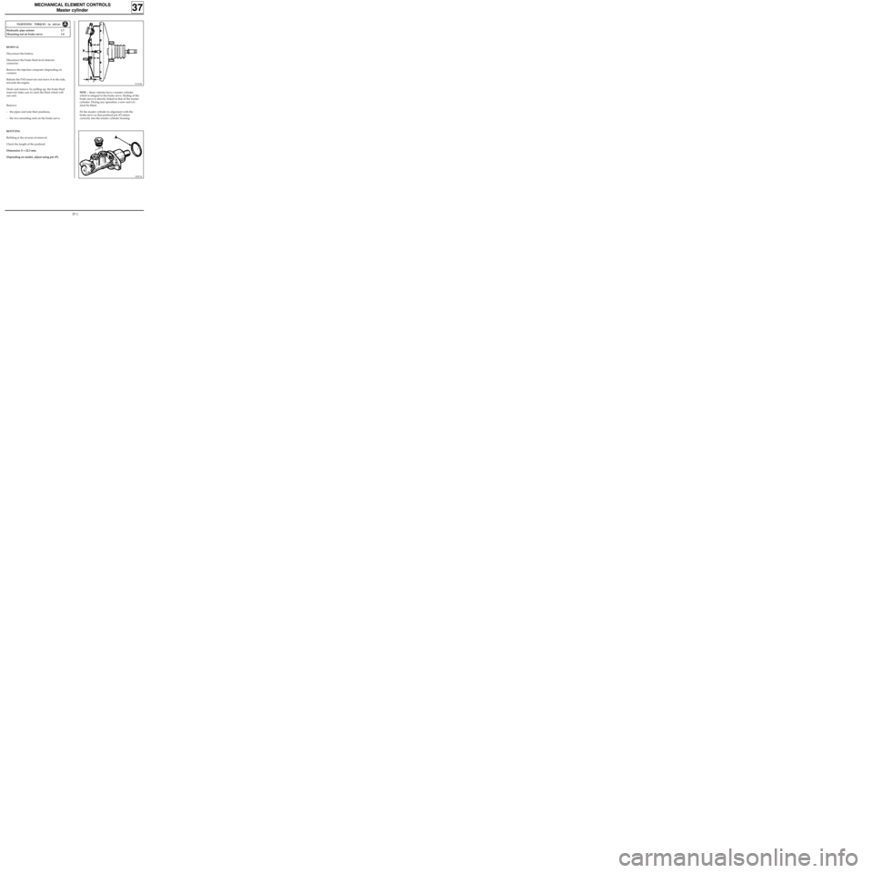
Check the length of the pushrod.
Dimension X = 22.3 mm.
Depending on model, adjust using pin (P).
91101R
NOTE : these vehicles have a master cylinder
which is integral to the brake servo. Sealing of the
brake servo is directly linked to that of the master
cylinder. During any operation, a new seal (A)
must be fitted.
Fit the master cylinder in alignment with the
brake servo so that pushrod pin (P) enters
correctly into the master cylinder housing.
TIGHTENING TORQUES (in daN.m)
DI3718
37-1
Page 70 of 105
MECHANICAL ELEMENT CONTROLS
Master cylinder
37
Fill the brake fluid reservoir and bleed the brake
circuit.
MASTER CYLINDER (EXCHANGE)
The kit sold by the Parts Department comprises :
- one master cylinder (4 outlets or 2 outlets for
ABS),
- two plugs (A),
- two mounting nuts (B).
DI3719
37-2
Page 71 of 105
MECHANICAL ELEMENT CONTROLS
Brake servo
TIGHTENING TORQUES (in daN.m)
Mounting nut on brake servo 1.8
Brake servo on bulkhead 2.3
- remove the 4 brake servo mounting nuts,
- remove the brake servo.
REFITTING
Before refitting, check:
-dimension L = 104.8 mm ,
-dimension X = 22.3 mm .The brake servo cannot be repaired. Operations
are only allowed on:
- the air filter,
- the non-return valve.
REMOVAL
Disconnect and remove the battery.
Remove:
- the master cylinder (following the method
described previously),
- the battery protection plate (4 bolts, 1 nut),
- the two mounting nuts for the expansion
bottle and move it towards the engine.
Disconnect the flexible vacuum hose from the
brake servo.
In the passenger compartment:
- remove the pin ( A ) from the clevice
connecting the brake pedal to the pushrod by
moving the clip,
37
91101R2
97860R
Refitting is the reverse of removal.
Bleed the brake circuit.
37-3
Page 72 of 105

SPECIAL TOOLING REQUIRED
Mot 453 -01 Hose clamp pliers
MECHANICAL ELEMENT CONTROLS
Brake servo
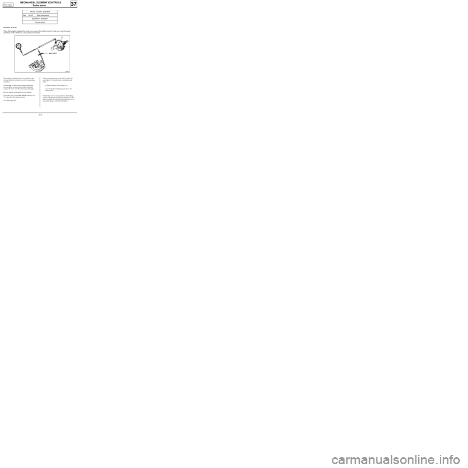
The sealing of the brake servo is checked on the
vehicle when the hydraulic circuit is in operating
condition.
Connect the vacuum pump between the brake
servo and the vacuum source (inlet manifold)
using a "T" union and the shortest possible pipe.
Run the engine at idle speed for one minute.
Clamp the pipe (clamp Mot. 453-01) between the
"T" union and the vacuum source.
Turn the engine off.If the vacuum drops by more than 33 mbar (25
mm/Hg) in 15 seconds, there is a leak located
either :
- at the non-return valve (replace it),
- or at the pushrod diaphragm (replace the
brake servo).
If the brake servo is not operational the braking
system will operate but the force required at the
pedal to obtain the equivalent deceleration as for
assisted braking is considerably higher .
CHECKING SEALING
When checking the sealing of the brake servo, ensure the seal between the brake servo and the master
cylinder is perfect. If there is a leak, replace the seal (A).
37
DI3701
EQUIPMENT REQUIRED
Vacuum pump
Petrol engine
37-4
Page 73 of 105
83 212
75 564
MECHANICAL ELEMENT CONTROLS
Air filter - Brake servo non-return valve
REPLACING THE AIR FILTER
To replace the air filter (F), the brake servo does
not need to be removed.
Under the pedal mounting, use a screwdriver or a
metal hook to remove the worn filter (F). Cut the
new filter at A (see diagram) and fit it around the
rod, then press it into position, checking that it
fills the complete opening to prevent any non-
filtered air from passing through.
REPLACING THE NON-RETURN VALVE
This operation may be carried out on the vehicle.
REMOVAL
Disconnect the brake servo vacuum inlet pipe.
Pull the non-return valve while twisting it to
release it from the rubber sealing washer.
REFITTING
Check the condition of the rubber sealing washer
and the non-return valve.
Replace any faulty parts.
Refit the assembly into position.
37
91101G74883S
37-5
Page 74 of 105
MECHANICAL ELEMENT CONTROLS
Vacuum pump
37
REMOVAL
Drain the cooling circuit.
Remove the air tube and its mounting.
Disconnect the quick release vacuum pipe.
Remove the thermostat mounting (2 bolts).
Remove the vacuum pump (2 bolts, 2 nuts).
13097-1S
Systematically renew the drive dog when repla-
cing the pump.
REFITTING
Refitting is the reverse of removal.
Bleed the brake circuit.
CHECKING
Engine warm, at 4000 rpm, the minimum vacuum
should be 700 mbar (525 mm/Hg) in 3 seconds.
Diesel engine
37-6