1997 NISSAN FRONTIER engine
[x] Cancel search: enginePage 17 of 204
CAUTION
Continued vehicle operation without hav-
ing the emission control system checked
and repaired as necessary could lead to
poor driveability, reduced fuel economy,
and possible damage to the emission
control system, which may affect your
warranty coverage.
Some conditions may cause the malfunction
indicator light to come on steady or blink.
Examples are as follows:
cvehicle ran out of fuel, which caused the
engine to misfire.
cfuel filler cap was left off or improperly
installed, allowing fuel to evaporate into
the atmosphere.
If you suspect that you experienced one or
both of the above conditions, drive the ve-
hicle to an authorized NISSAN dealer and
have the vehicle inspected. Avoid any un-
necessary diagnosis during the service by
informing the dealer of the conditions listed
above that may have cccurred.
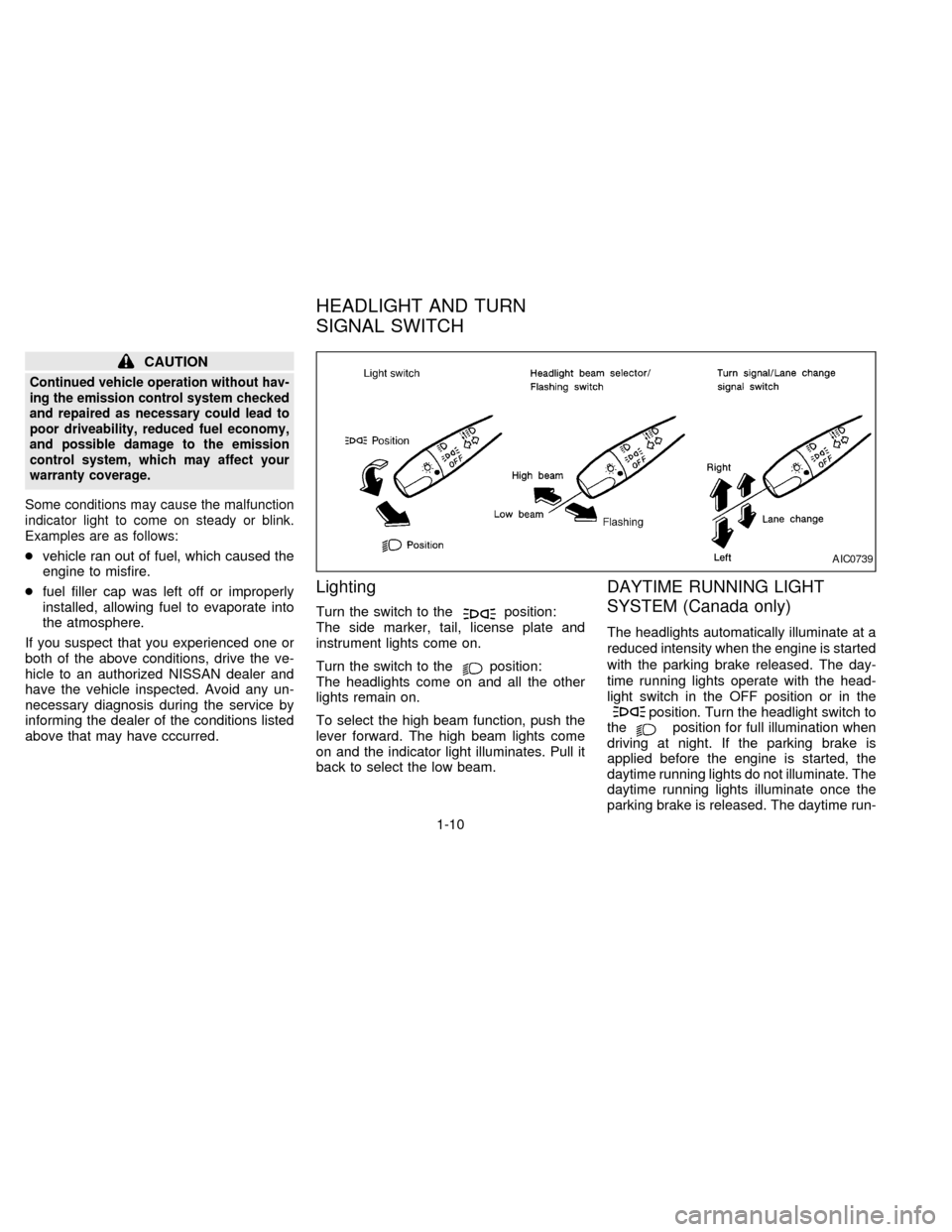
Lighting
Turn the switch to theposition:
The side marker, tail, license plate and
instrument lights come on.
Turn the switch to the
position:
The headlights come on and all the other
lights remain on.
To select the high beam function, push the
lever forward. The high beam lights come
on and the indicator light illuminates. Pull it
back to select the low beam.
DAYTIME RUNNING LIGHT
SYSTEM (Canada only)
The headlights automatically illuminate at a
reduced intensity when the engine is started
with the parking brake released. The day-
time running lights operate with the head-
light switch in the OFF position or in the
position. Turn the headlight switch to
theposition for full illumination when
driving at night. If the parking brake is
applied before the engine is started, the
daytime running lights do not illuminate. The
daytime running lights illuminate once the
parking brake is released. The daytime run-
AIC0739
HEADLIGHT AND TURN
SIGNAL SWITCH
1-10
ZX
Page 31 of 204
WARNING
cMake sure the hood is completely
closed and latched before driving.
Failure to do so could cause the
hood to fly open and result in an
accident.
cIf you see steam or smoke coming
from the engine compartment, to
avoid injury do not open the hood.
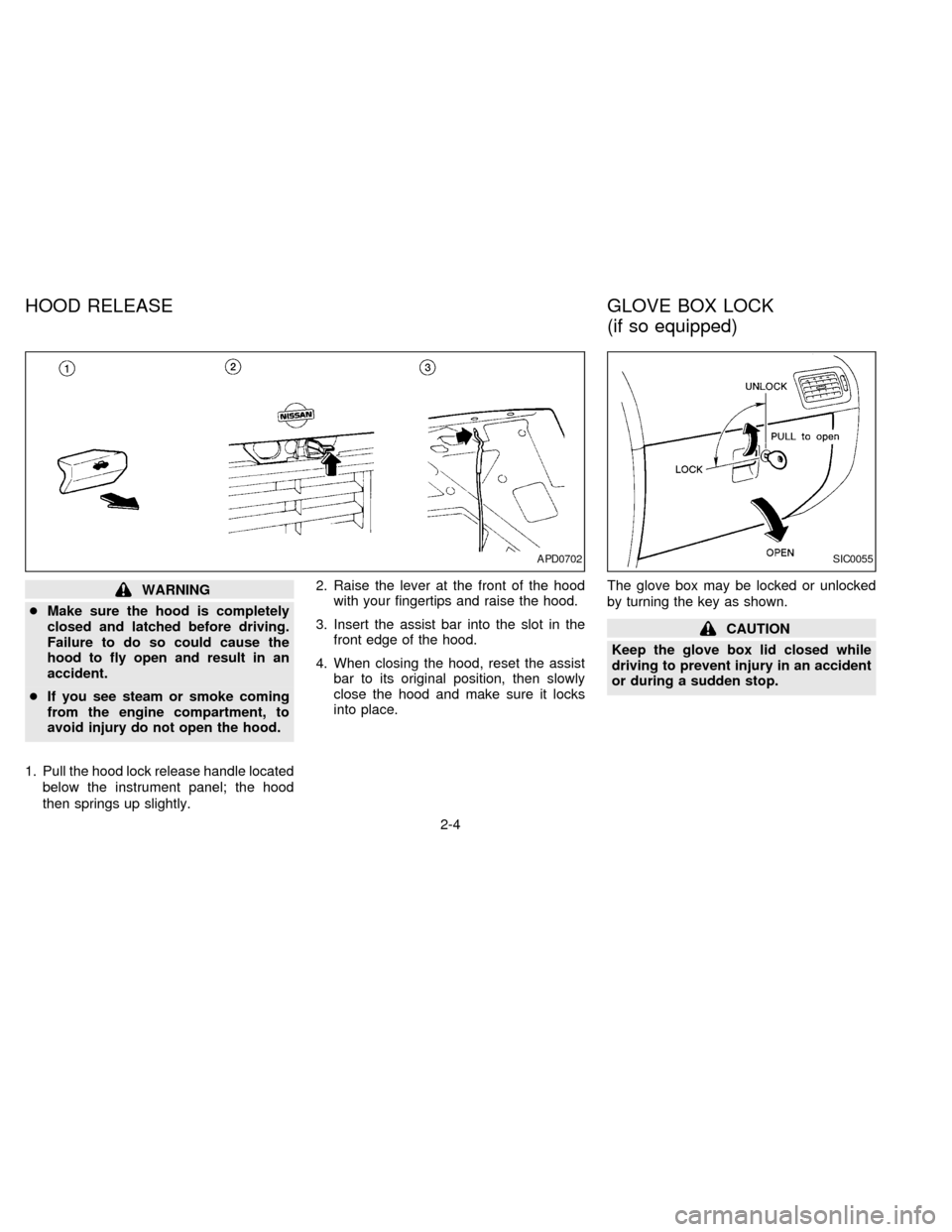
1. Pull the hood lock release handle located
below the instrument panel; the hood
then springs up slightly.2. Raise the lever at the front of the hood
with your fingertips and raise the hood.
3. Insert the assist bar into the slot in the
front edge of the hood.
4. When closing the hood, reset the assist
bar to its original position, then slowly
close the hood and make sure it locks
into place.The glove box may be locked or unlocked
by turning the key as shown.
CAUTION
Keep the glove box lid closed while
driving to prevent injury in an accident
or during a sudden stop.
APD0702SIC0055
HOOD RELEASE GLOVE BOX LOCK
(if so equipped)
2-4
ZX
Page 32 of 204
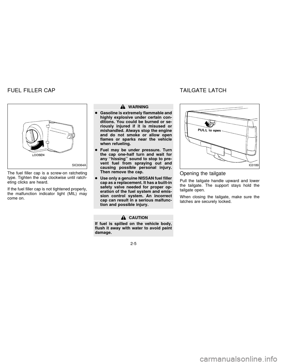
The fuel filler cap is a screw-on ratcheting
type. Tighten the cap clockwise until ratch-
eting clicks are heard.
If the fuel filler cap is not tightened properly,
the malfunction indicator light (MIL) may
come on.
WARNING
cGasoline is extremely flammable and
highly explosive under certain con-
ditions. You could be burned or se-
riously injured if it is misused or
mishandled. Always stop the engine
and do not smoke or allow open
flames or sparks near the vehicle
when refueling.
cFuel may be under pressure. Turn
the cap one-half turn and wait for
any ``hissing'' sound to stop to pre-
vent fuel from spraying out and
causing possible personal injury.
Then remove the cap.
cUse only a genuine NISSAN fuel filler
cap as a replacement. It has a built-in
safety valve needed for proper op-
eration of the fuel system and emis-
sion control system. An incorrect
cap can result in a serious malfunc-
tion and possible injury.
CAUTION
If fuel is spilled on the vehicle body,
flush it away with water to avoid paint
damage.
Opening the tailgate
Pull the tailgate handle upward and lower
the tailgate. The support stays hold the
tailgate open.
When closing the tailgate, make sure the
latches are securely locked.
SIC0064AIC0189
FUEL FILLER CAP TAILGATE LATCH
2-5
ZX
Page 52 of 204
cAn improperly installed child re-
straint could lead to serious injury or
death in an accident.
In general, child restraints are designed to
be installed with a lap belt or the lap portion
of a 3-point type seat belt. Child restraints
specially designed for infants and small
children are offered by several manufactur-
ers. When selecting any child restraint,
keep the following points in mind:
1) Choose only a restraint with a label cer-
tifying that it complies with Federal Motor
Vehicle Safety Standard 213 or Cana-
dian Motor Vehicle Safety Standard 213.
2) Check the child restraint in your vehicle
to be sure it is compatible with the vehi-
cle's seat and seat belt system. Choose
a child restraint that meets the guidelines
of the Society of Automotive Engineers
recommended practice J1819 for child
restraint installation.
3) If the child restraint is compatible with
your vehicle, place your child in the child
restraint and check the various adjust-
ments to be sure the child restraint is
compatible with your child. Always follow
all of the recommended procedures.All U.S. states and provinces of Canada
require that infants and small children be
restrained in an approved child restraint
at all times while the vehicle is being
operated.
WARNING
cDo not install a child restraint in the
jump seats (King Cab model). These
seats are not suitable for child re-
straint installation.
cImproper use of a child restraint can
result in increased injuries for both
the infant or child and other occu-
pants in the vehicle.
cFollow all of the child restraint
manufacturer's instructions for in-
stallation and use. When purchasing
a child restraint, be sure to select
one which will fit your child and
vehicle as it may not be possible to
properly install some types of child
restraints in your vehicle.
cIf the child restraint is not anchored
properly, the risk of a child being
injured in a collision or a sudden
stop greatly increases.cAdjustable seatbacks should be po-
sitioned to fit the child restraint, but
as upright as possible.
c
After attaching the child restraint,
test it before you place the child in it.
Tilt it from side to side. Try to tug it
forward and check to see if the belt
holds the restraint in place. If the
restraint is not secure, tighten the
belt as necessary, or put the restraint
in another seat and test it again.
cFor a front facing child restraint,
check to make sure the shoulder belt
does not go in front of the child's
face or neck. If it does, put the shoul-
der belt behind the child restraint.
cWhen your child restraint is not in
use, keep it secured with a seat belt
to prevent it from being thrown
around in case of a sudden stop or
accident.
CAUTION
Remember that a child restraint left in a
closed vehicle can become very hot.
Check the seating surface and buckles
before placing your child in the child
restraint.
2-25
ZX
Page 62 of 204
WARNING
cThe air conditioner cooling function
operates only when the engine is
running.
cDo not leave children, unreliable
adults, or pets alone in your vehicle.
On hot sunny days, temperatures in
a closed vehicle could quickly be-
come high enough to cause severe
or possibly fatal injuries to people or
animals.
cDo not use the recirculation mode
for long periods as it may cause theinterior air to become stale and the
windows to fog up.
cPositioning of the heating or air con-
ditioning controls should not be
done while driving, so that full atten-
tion may be given to the driving
operation.
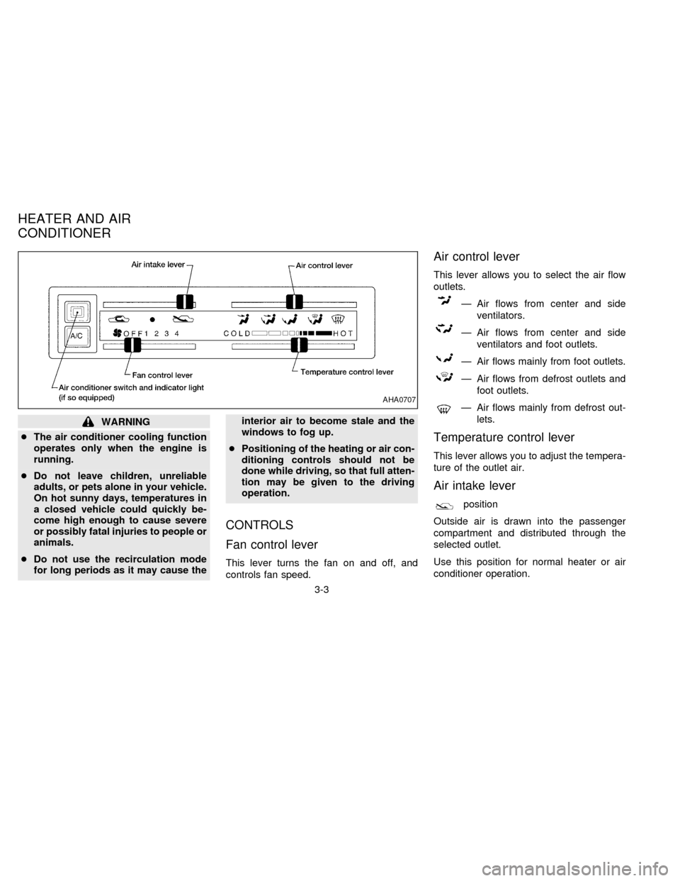
CONTROLS
Fan control lever
This lever turns the fan on and off, and
controls fan speed.
Air control lever
This lever allows you to select the air flow
outlets.
Ð Air flows from center and side
ventilators.
Ð Air flows from center and side
ventilators and foot outlets.
Ð Air flows mainly from foot outlets.
Ð Air flows from defrost outlets and
foot outlets.
Ð Air flows mainly from defrost out-
lets.
Temperature control lever
This lever allows you to adjust the tempera-
ture of the outlet air.
Air intake lever
position
Outside air is drawn into the passenger
compartment and distributed through the
selected outlet.
Use this position for normal heater or air
conditioner operation.
AHA0707
HEATER AND AIR
CONDITIONER
3-3
ZX
Page 63 of 204

position
Interior air is recirculated inside the vehicle.
Move the air intake lever to the
posi-
tion:
cwhen driving on a dusty road.
cto prevent traffic fumes from entering the
passenger compartment.
cfor maximum cooling when using the air
conditioner.
Air conditioner switch
(if so equipped)
This button is provided only for vehicles with
an air conditioner.
Start the engine, push the switch and move
the fan control lever to the desired speed.
The indicator light comes on when the air
conditioner is on.
HEATER OPERATION
Heating
This mode directs hot air to the foot outlets.
A small amount of air is also directed to the
defrost outlets.
1. Move the air intake lever to the
po-sition for normal heating.
2. Move the air control lever to the
position.
3. Move the fan control lever to the desired
speed.
4. Move the temperature control lever to the
desired position between the middle and
the HOT position.
Ventilation
This mode directs outside air to the side and
center ventilators.
1. Move the air intake lever to the
po-
sition.
2. Move the air control lever to the
position.
3. Move the fan control lever to the desired
speed.
4. Move the temperature control lever to the
desired position.
Defrosting or defogging
This mode defrosts/defogs the windows.
1. Move the air intake lever to the
po-
sition.2. Move the air control lever to the
position.
3. Move the fan control lever to the desired
speed.
4. Move the temperature control lever to the
desired position between the middle and
the HOT position.
cIf it is difficult to defog the windshield,
turn the air conditioner switch on (if so
equipped).
Bi-level heating
This mode directs cooler air from the side
and center ventilators and warmer air from
the foot outlets.
1. Move the air intake lever to the
po-
sition.
2. Move the air control lever to the
position.
3. Move the fan control lever to the desired
speed.
4. Move the temperature control lever to the
desired position.
3-4
ZX
Page 64 of 204

Heating and defrosting
This mode heats the interior and defogs the
windshield.
1. Move the air intake lever to the
po-
sition.
2. Move the air control lever to the
position.
3. Move the fan control lever to the desired
speed.
4. Move the temperature control lever to the
desired position between the middle and
the HOT position.
Operating tips
Clear snow and ice from the wiper blade
and air inlet in front of the windshield. This
improves heater and defroster operation.
AIR CONDITIONER OPERATION
(if so equipped)
Start the engine, move the fan control lever
to the desired (1 to 4) position, and push in
the air conditioner switch to activate the air
conditioner. When the air conditioner is on,
cooling and dehumidifying functions are
added to the heater operation.The air conditioner cooling function op-
erates only when the engine is running.
Cooling
This mode cools and dehumidifies.
1. Move the air intake lever to the
po-
sition.
2. Move the air control lever to the
position.
3. Move the fan control lever to the desired
position.
4. Push in the air conditioner switch. The
indicator light comes on.
5. Move the temperature control lever to the
desired position.
cFor quick cooling when the outside tem-
perature is high, move the air intake lever
to the
position. Be sure to return
the air intake lever to theposition
for normal cooling.
Dehumidified heating
This mode heats and dehumidifies.
1. Move the air intake lever to the
po-
sition.
2. Move the air control lever to the
position.3. Move the fan control lever to the desired
position.
4. Push in the air conditioner switch. The
indicator light comes on.
5. Move the temperature control lever to the
desired position.
Dehumidified defrosting
This mode defrosts/defogs the windows and
dehumidifies.
1. Move the air intake lever to the
po-
sition.
2. Move the air control lever to the
position.
3. Move the fan control lever to the desired
position.
4. Push in the air conditioner switch. The
indicator light comes on.
5. Move the temperature control lever to the
desired position.
Operating tips
cKeep windows and sunroof closed while
operating the air conditioner.
cAfter parking in the sun, drive for two or
3-5
ZX
Page 69 of 204

To turn the radio on, turn the ignition key to
ACC or ON. If you listen to the radio when
the engine is not running, turn the key to the
ACC position.
Radio reception is affected by station signal
strength, distance from radio transmitter,
buildings, bridges, mountains and other ex-
ternal influences. Intermittent changes in
reception quality normally are caused by
these external influences.
AHA0709
AUDIO SYSTEM
3-10
ZX