1997 MERCEDES-BENZ ML500 ECU
[x] Cancel search: ECUPage 314 of 4133
264 Exterior lamps
Te ch n ica l
data Instruments
and controlsOperation DrivingInstrument
cluster displayPractical hintsCar care Index
Parking, standing, side marker and turn signal lamp
115 6 N A ( 3 2 / 4 c p b u l b )
Open hood.
Twist bulb socket (4) counterclockwise and pull out.
Push bulb into socket, turn counterclockwise and
remove.
Insert new bulb in socket, push in and twist clockwise.
Reinstall bulb socket.Bulbs for auxiliary fog lamp (optional)
H3 U (55 W)
Open hood.
Remove cover (9). Unhook clamping ring and remove
bulb. Pull off electrical connector.
Insert new bulb in socket (seating properly in cutouts of
bulb socket), and mount clamping ring. Reinstall and
push electrical connector on securely.
Reinstall cover (9).
Page 317 of 4133
![MERCEDES-BENZ ML500 1997 Complete Repair Manual 267 Exterior lamps
Te ch n ica l
data Instruments
and controlsOperation DrivingInstrument
cluster displayPractical hintsCar care Index License plate lamps (C 5 W [tubular] bulb)
Remove both securing MERCEDES-BENZ ML500 1997 Complete Repair Manual 267 Exterior lamps
Te ch n ica l
data Instruments
and controlsOperation DrivingInstrument
cluster displayPractical hintsCar care Index License plate lamps (C 5 W [tubular] bulb)
Remove both securing](/manual-img/4/57308/w960_57308-316.png)
267 Exterior lamps
Te ch n ica l
data Instruments
and controlsOperation DrivingInstrument
cluster displayPractical hintsCar care Index License plate lamps (C 5 W [tubular] bulb)
Remove both securing screws, remove lamp and take
out bulb.High mounted stop lamp (1073 [32 cp bulb])
To replace bulb, squeeze both sides (1, arrows) of cover,
fold forward and remove.
Press tab (2, arrow) on reflector and remove reflector.
Press bulb down, turn counterclockwise and remove.
Insert new bulb in socket, push in and twist clockwise.
Reinstall reflector.
Position tabs of cover in slots (3, arrows) and reinstall
cover until properly seated.
P82.10-2347-26
P82.10-2346-26
Page 368 of 4133
DISABLING SYSTEM
Before proceeding, see AIR BAG SAFETY PRECAUTIONS . Record radio presets and obtain anti-theft
code. Turn ignition switch to OFF position and remove ignition key. If welding on vehicle, disconnect negative
battery cable and disconnect air bag control module.
ACTIVATING SYSTEM
Ensure ignition is off. Reconnect air bag system co mponents (if disconnected). Reconnect negative battery
cable. Perform See SYSTEM OPERATION CHECK
.
DISPOSAL PROCEDURES
Several situations may arise requiring so me form of disposal action, including:
Scrapping a vehicle containing a deployed air bag module and-or ETR.
Scrapping a vehicle with a live air bag module and-or ETR.
Disposal of a live but electrically faulty air bag module and-or ETR.
Disposal of a deployed air bag module and-or ETR.
DEPLOYED AIR BAG OR ETR
Deployed air bag module and-or ETR unit can be thrown away. None of its components are reusable. Deployed
air bag module is NOT classified as hazardous material.
SCRAPPED VEHICLE
1. Before proceeding, follow service precautions. See AIR BAG SAFETY PRECAUTIONS . Move
vehicle outdoors to a remote area, away from work shop and other personnel. Disconnect and shield
negative battery cable. Open al l vehicle windows and doors.
2. Ensure air bag module is secured to steering wheel, and passenger air bag is secured to dash. Ensure ETR
seat belt assemblies are secured to "B" pillars and all seat belt buckles are latched. Remove loose ob
jects
CAUTION: On CL500, open doors before
disconnecting battery. Opening doors
allows windows to automa tically lower thus preventing roof seal damage.
WARNING: An undeployed air bag module or ET R should never be disposed of
without first being deplo yed. See SCRAPPED VEHICLE
. If deployment is
not possible, contact vehicle manuf acturer for further instructions.
WARNING: An undeployed air bag m odule and-or ETR seat belt CANNOT be disposed
of without first being de ployed. If this is not possible through procedures
outlined below, contact vehicle ma nufacturer for further instructions.
Perform remote deployment outdoors . Keep personnel at least 20 feet
away.
2001 Mercedes-Benz ML320
2000-01 ACCESSORIES/SAFETY EQUIPMENT Merc edes-Benz - Air Bag Restraint Systems
me
Saturday, October 02, 2010 3:44:45 PMPage 4 © 2006 Mitchell Repair Information Company, LLC.
Page 378 of 4133
Disconnect passenger-side air bag module squib connector. Remove 4 passenger-side air bag module
mounting nuts.
2. To install, reverse removal proc edure. Ensure passenger-side air bag module squib connector audibly
clicks when connecting connector. Activate air bag system. Perform system operation check to ensure
system is functioning properly. See SYSTEM OPERATION CHECK
.
Removal & Installation (E Class)
1. Before proceeding, See AIR BAG SAFETY PRECAUTIONS . Disable air bag system. See
DISABLING & ACTIVATI NG AIR BAG SYSTEM
. Remove ignition key. Remove 2 central
mounting bolts for passenger-side air bag module. Li ft air bag module enough to unplug connector from
rear of module. Place module away fr om work area, with pad facing upward.
2. If necessary to replace passenger air bag instal lation frame, remove 4 frame mounting bolts. Remove
installation frame from vehicle.
3. To install air bag module or inst allation frame, reverse removal proc edure. Activate air bag system.
Perform system operation check to ensu re system is functioning properly. See SYSTEM OPERATION
CHECK .
Removal & Installation (S Class)
1. Before proceeding, See AIR BAG SAFETY PRECAUTIONS . Disable air bag system. See
DISABLING & ACTIVATI NG AIR BAG SYSTEM
. Remove ignition key. Open glove box door.
Remove 4 clips securing glove bo x. Remove glove box compartment. When removing compartment,
disconnect glove box light. Remove glove box door lock striker.
2. Disconnect passenger-side air bag module squib c onnector. Remove 4 passenger-side air bag module
mounting nuts. Remove passenger- side air bag module through glove box opening. Place module away
from work area with pad facing up.
3. To install, reverse removal proc edure. Ensure module squib connector audibly clicks when connecting
connector. Activate air bag system. Perform system operation check to ensure system is functioning
properly. See SYSTEM OPERATION CHECK
.
Removal & Installation (SL Class)
1. Before proceeding, See AIR BAG SAFETY PRECAUTIONS . Disable air bag system. See
DISABLING & ACTIVATI NG AIR BAG SYSTEM
. Remove ignition key. Remove cover below
instrument panel. Remove one bolt in installation slot of center air outlet, and one bolt below right air
outlet.
2. Remove air bag panel (3 Phillips screws and 2 hex bol ts). Unplug connector at squib of passenger-side air
bag unit. Remove mounting bo lts. Pull off and take air bag out of panel opening.
3. To install air bag module, reverse removal procedur e. Activate air bag system. Perform system operation
check to ensure system is functioning properly. See SYSTEM OPERATION CHECK
.
Removal & Installation (CLK 320)
1. Before proceeding, See AIR BAG SAFETY PRECAUTIONS . Disable air bag system. See
DISABLING & ACTIVATI NG AIR BAG SYSTEM
. Remove ignition key. Remove instrument panel.
Disconnect passen
ger-side air bag module connector. Remove 4 screws and passenger-side air bag
2001 Mercedes-Benz ML320
2000-01 ACCESSORIES/SAFETY EQUIPMENT Merc edes-Benz - Air Bag Restraint Systems
me
Saturday, October 02, 2010 3:44:45 PMPage 14 © 2006 Mitchell Repair Information Company, LLC.
Page 380 of 4133
not latched. See Fig. 5 .
4. These graphic displays are disp layed as applicable by HHT during testing. See FAULT CODES table.
During diagnosis, system values are continuously updated, so by moving components and connections
intermittent failures can be diagnosed. HHT will also display fault frequency and time span.
5. After retrieving fault codes using HHT, carefully observe testing instructions in this article. Some testing
is executed with HHT connected to DLC and some tests are executed with HHT removed from DLC.
Turn ignition off when removing or connecting HHT to DLC.
6. Contact Box (124 589 00 21) with Test Cable (124 589 35 63) is necessary to complete some test steps.
Resistance Substitution Unit (124 589 09 63) is necessa ry to substitute resistance values for testing
purposes.
2001 Mercedes-Benz ML320
2000-01 ACCESSORIES/SAFETY EQUIPMENT Merc edes-Benz - Air Bag Restraint Systems
me
Saturday, October 02, 2010 3:44:45 PMPage 16 © 2006 Mitchell Repair Information Company, LLC.
Page 492 of 4133
25
Central locking system
Te ch n ica l
data
Instruments
and controls Operation
Driving Instrument
cluster display Practical hints Car care Index
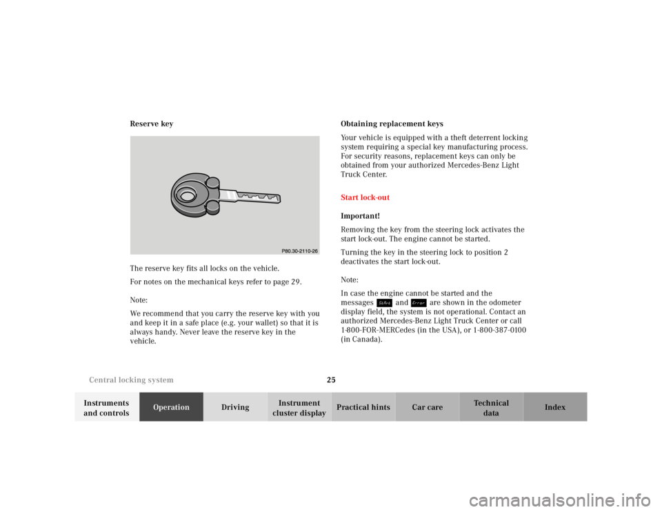
Reserve key
The reserve key fits all locks on the vehicle.
For notes on the mechanical keys refer to page 29.
Note:
We recommend that you carry the reserve key with you
and keep it in a safe place (e.g. your wallet) so that it is
always handy. Never leave the reserve key in the
vehicle. Obtaining replacement keys
Your vehicle is equipped with a theft deterrent locking
system requiring a special key manufacturing process.
For security reasons, replacement keys can only be
obtained from your authorized Mercedes-Benz Light
Truck Center.
Start lock-out
Important!
Removing the key from the steering lock activates the
start lock-out. The engine cannot be started.
Turning the key in the steering lock to position 2
deactivates the start lock-out.
Note:
In case the engine cannot be started and the
messages Á and î are shown in the odometer
display field, the system is not operational. Contact an
authorized Mercedes-Benz Light Truck Center or call
1-800-FOR-MERCedes (in the USA), or 1-800-387-0100
(in Canada).
Page 505 of 4133
38
Seats
Te ch n ica l
data
Instruments
and controls Operation
Driving Instrument
cluster display Practical hints Car care Index
Important!
Prior to operating the vehicle, the driver should adjust
the seat height for proper vision as well as fore / aft
placement and backrest angle to insure adequate
control, reach, operation, and comfort. The head
restraint should also be adjusted for proper height. See
also airbag section on page 56 for proper seat
positioning.
In addition, also adjust the steering wheel to ensure
adequate control, reach, operation, and comfort.
Both the inside and outside rear view mirrors should be
adjusted for adequate rearward vision.
Fasten seat belts. Infants and small children should be
seated in a properly secured restraint system that
complies with U.S. Federal Motor Vehicle Safety
Standard 213 and Canadian Motor Vehicle Safety
Standard 213.
All seat, head restraint, steering wheel, and rear view
mirror adjustments as well as fastening of seat belts
should be done before the vehicle is put into motion.
Wa r n i n g !
Children 12 years old and under must never ride in
the front seat, except in a Mercedes-Benz
authorized BabySmart
TM compatible child seat,
which operates with the BabySmart
TM system
installed in the vehicle to deactivate the passenger
side front airbag when it is properly installed.
Otherwise they will be struck by the airbag when it
inflates in a crash. If this happens, serious or fatal
injury can result.
According to accident statistics, children are safer
when properly restrained in the rear seating
positions than in the front seating positions.
Infants and small children must ride in the back
seats and be seated in an appropriate infant or
child restraint system, which is properly secured
with the vehicle’s seat belt, fully in accordance
with the child seat manufacturer’s instructions.A child’s risk of serious or fatal injuries is
significantly increased if the child restraints are
not properly secured in the vehicle and the child is
not properly secured in the child restraint.
Page 513 of 4133
46
Restraint systems
Te ch n ica l
data
Instruments
and controls Operation
Driving Instrument
cluster display Practical hints Car care Index
Seat belts and integrated restraint system
Your vehicle is equipped with seat belts for all seats,
emergency tensioning retractors for front and second
row outboard seat belts, dual front airbags and door
mounted side impact airbags. Their protective functions
are designed to complement one another.
Seat belts
Important!
Laws in most states and all Canadian provinces require
seat belt use.
All states and provinces require use of child restraints
that comply with U.S. Federal Motor Vehicle Safety
Standard 213 and Canadian Motor Vehicle Safety
Standard 213.
All child restraint systems are designed to be secured in
vehicle seats by lap belts or the lap belt portion of a lap-
shoulder belt.
For your safety and that of your passengers we strongly
recommend their use.
Wa r n i n g !
Children 12 years old and under must never ride in
the front seat, except in a Mercedes-Benz
authorized BabySmart
TM compatible child seat,
which operates with the BabySmart
TM system
installed in the vehicle to deactivate the passenger
side front airbag when it is properly installed.
Otherwise they will be struck by the airbag when it
inflates in a crash. If this happens, serious or fatal
injury will result.
According to accident statistics, children are safer
when properly restrained in the rear seating
positions than in the front seating positions.
Infants and small children must ride in back seats
and be seated in an appropriate infant or child
restraint system, which is properly secured with
the vehicle’s seat belt, fully in accordance with the
child seat manufacturer’s instructions.A child’s risk of serious or fatal injuries is
significantly increased if the child restraints are
not properly secured in the vehicle and the child is
not properly secured in the child restraint.