Page 1745 of 4133
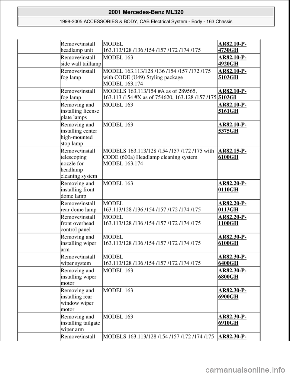
Remove/install
headlamp unitMODEL
163.113/128 /136 /154 /157 /172 /174 /175AR82.10-P-
4730GH
Remove/install
side wall taillampMODEL 163AR82.10-P-
4920GH
Remove/install
fog lampMODEL 163.113/128 /136 /154 /157 /172 /175
with CODE (U49) Styling package
MODEL 163.174AR82.10-P-
5103GH
Remove/install
fog lampMODELS 163.113/154 #A as of 289565,
163.113 /154 #X as of 754620, 163.128 /157 /175AR82.10-P-
5103GI
Removing and
installing license
plate lampsMODEL 163AR82.10-P-
5161GH
Removing and
installing center
high-mounted
stop lampMODEL 163AR82.10-P-
5375GH
Remove/install
telescoping
nozzle for
headlamp
cleaning systemMODELS 163.113/128 /154 /157 /172 /175 with
CODE (600a) Headlamp cleaning system
MODEL 163.174AR82.15-P-
6100GH
Removing and
installing front
dome lampMODEL 163AR82.20-P-
0110GH
Remove/install
rear dome lampMODEL
163.113/128 /136 /154 /157 /172 /174 /175AR82.20-P-
0113GH
Remove/install
front overhead
control panelMODEL
163.113/128 /136 /154 /157 /172 /174 /175AR82.20-P-
1100GH
Removing and
installing wiper
armMODEL
163.113/128 /136 /154 /157 /172 /174 /175AR82.30-P-
6100GH
Remove/install
wiper systemMODEL
163.113/128 /136 /154 /157 /172 /174 /175AR82.30-P-
6400GH
Removing and
installing wiper
motorMODEL 163AR82.30-P-
6800GH
Removing and
installing rear
window wiper
motorMODEL 163AR82.30-P-
6900GH
Removing and
installing tailgate
wiper armMODEL 163AR82.30-P-
6910GH
Remove/install MODELS 163.113/128 /154 /157 /172 /174 /175 AR82.30-P-
2001 Mercedes-Benz ML320
1998-2005 ACCESSORIES & BODY, CAB Electrical System - Body - 163 Chassis
me
Saturday, October 02, 2010 3:30:08 PMPage 250 © 2006 Mitchell Repair Information Company, LLC.
Page 1759 of 4133
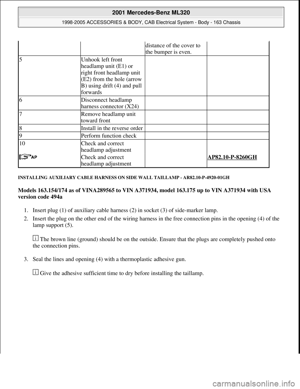
INSTALLING AUXILIARY CABLE HARNESS ON SIDE WALL TAILLAMP - AR82.10-P-4920-01GH
Models 163.154/174 as of VINA289565 to VIN A371934, model 163.175 up to VIN A371934 with USA
version code 494a
1. Insert plug (1) of auxiliary cable harness (2) in socket (3) of side-marker lamp.
2. Insert the plug on the other end of the wiring harness in the free connection pins in the opening (4) of the
lamp support (5).
The brown line (ground) should be on the outside. Ensure that the plugs are completely pushed onto
the connection pins.
3. Seal the lines and opening (4) with a thermoplastic adhesive gun.
Give the adhesive sufficient time to dr
y before installing the taillamp.
distance of the cover to
the bumper is even.
5Unhook left front
headlamp unit (E1) or
right front headlamp unit
(E2) from the hole (arrow
B) using drift (4) and pull
forwards
6Disconnect headlamp
harness connector (X24)
7Remove headlamp unit
toward front
8Install in the reverse order
9Perform function check
10Check and correct
headlamp adjustment
Check and correct
headlamp adjustment AP82.10-P-8260GH
2001 Mercedes-Benz ML320
1998-2005 ACCESSORIES & BODY, CAB Electrical System - Body - 163 Chassis
me
Saturday, October 02, 2010 3:30:09 PMPage 264 © 2006 Mitchell Repair Information Company, LLC.
Page 1760 of 4133
Fig. 164: Identifying Auxiliary Cabl e Harness On Side Wall Taillamp
REMOVE/INSTALL SIDE WALL TAILLAMP - AR82.10-P-4920GH
MODEL 163
Fig. 165: Identifying Side Wall Taillamp
Remove/Install
2001 Mercedes-Benz ML320
1998-2005 ACCESSORIES & BODY, CAB Electr ical System - Body - 163 Chassis
me
Saturday, October 02, 2010 3:30:09 PMPage 265 © 2006 Mitchell Repair Information Company, LLC.
Page 1761 of 4133
REMOVE/INSTALL FOG LAMP - AR82.10-P-5103GH
MODEL 163.113 /128 /136 /154 /157 /172 /175 with CODE (U49) Styling package
MODEL 163.174
Fig. 166: Identifying Fog Lamp Components
1Open rear flap
2Unscrew nuts(1)
3Pull back left taillamp
(E3) or right taillamp (E4) Installation: Insert
spigot (2) in the support
(3).
4Unplug connector (4)
5Take out taillamp
6.1Install auxiliary wiring
harness Only if the taillamp is
replaced. Only on USA
version vehicles, code
494a and as of VIN
A289565 up to A371934.AR82.10-P-4920-01GH
7Install in the reverse order
8Perform function check
Remove/Install
2001 Mercedes-Benz ML320
1998-2005 ACCESSORIES & BODY, CAB Electrical System - Body - 163 Chassis
me
Saturday, October 02, 2010 3:30:09 PMPage 266 © 2006 Mitchell Repair Information Company, LLC.
Page 1972 of 4133
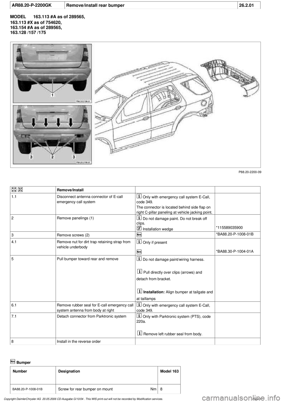
AR88.20-P-2200GK
Remove/install rear bumper
26.2.01
MODEL
163.113 #A as of 289565,
163.113 #X as of 754620,
163.154 #A as of 289565,
163.128 /157 /175
P88.20-2200-09
Remove/Install
1.1
Disconnect antenna connector of E-call
emergency call system
Only with emergency call system E-Call,
code 349.
The connector is located behind side flap on
right C-pillar paneling at vehicle jacking point.
2
Remove panelings (1)
Do not damage paint. Do not break off
clips.
Installation wedge
*115589035900
3
Remove screws (2)
*BA88.20-P-1008-01B
4.1
Remove nut for dirt trap retaining strap from
vehicle underbody
Only if present
*BA88.30-P-1004-01A
5
Pull bumper toward rear and remove
Do not damage paint/wiring harness.
Pull directly over clips (arrows) and
detach from bracket.
Installation:
Align bumper at tailgate and
at taillamps
6.1
Remove rubber seal for E-call emergency call
system antenna from body at right
Only with emergency call system E-Call,
code 349.
7.1
Detach connector from Parktronic system
Only with Parktronic system (PTS), code
220a.
Remove left rubber seal from body.
8
Install in the reverse order
Bumper
Number
Designation
Model 163
BA88.20-P-1008-01B
Screw for rear bumper on mount
Nm
8
Copyright DaimlerChrysler AG 20.05.2006 CD-Ausgabe G/10/04 . This WIS print-out will not be recorde
d by Modification services.
Page 1
Page 1982 of 4133
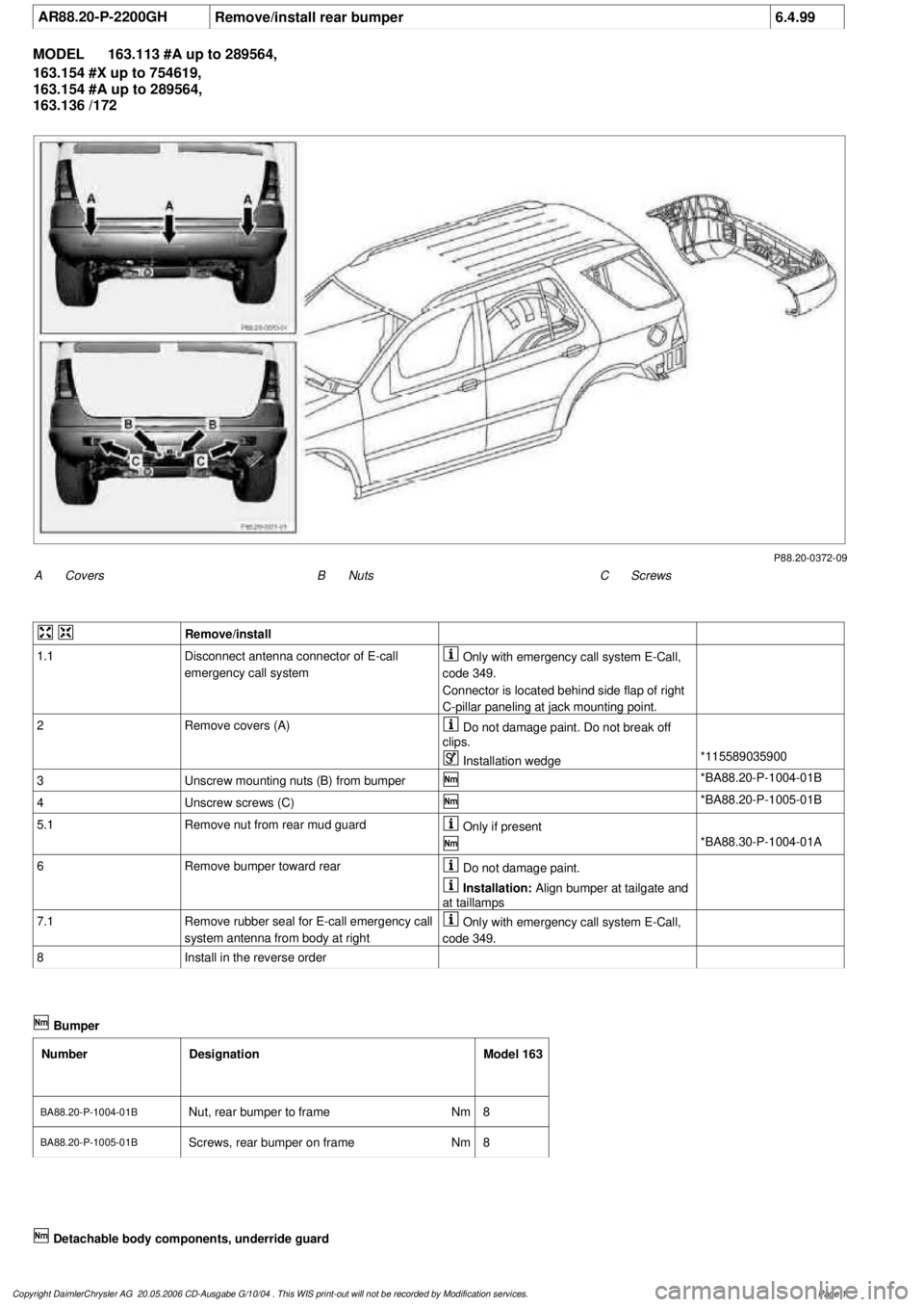
AR88.20-P-2200GH
Remove/install rear bumper
6.4.99
MODEL
163.113 #A up to 289564,
163.154 #X up to 754619,
163.154 #A up to 289564,
163.136 /172
P88.20-0372-09
A
Covers
C
Screws
B
Nuts
Remove/install
1.1
Disconnect antenna connector of E-call
emergency call system
Only with emergency call system E-Call,
code 349.
Connector is located behind side flap of right
C-pillar paneling at jack mounting point.
2
Remove covers (A)
Do not damage paint. Do not break off
clips.
Installation wedge
*115589035900
3
Unscrew mounting nuts (B) from bumper
*BA88.20-P-1004-01B
4
Unscrew screws (C)
*BA88.20-P-1005-01B
5.1
Remove nut from rear mud guard
Only if present
*BA88.30-P-1004-01A
6
Remove bumper toward rear
Do not damage paint.
Installation:
Align bumper at tailgate and
at taillamps
7.1
Remove rubber seal for E-call emergency call
system antenna from body at right
Only with emergency call system E-Call,
code 349.
8
Install in the reverse order
Bumper
Number
Designation
Model 163
BA88.20-P-1004-01B
Nut, rear bumper to frame
Nm
8
BA88.20-P-1005-01BScrews, rear bumper on frame
Nm
8
Copyright DaimlerChrysler AG 20.05.2006 CD-Ausgabe G/10/04 . This WIS print-out will not be recorde
d by Modification services.
Page 1
Page 1984 of 4133
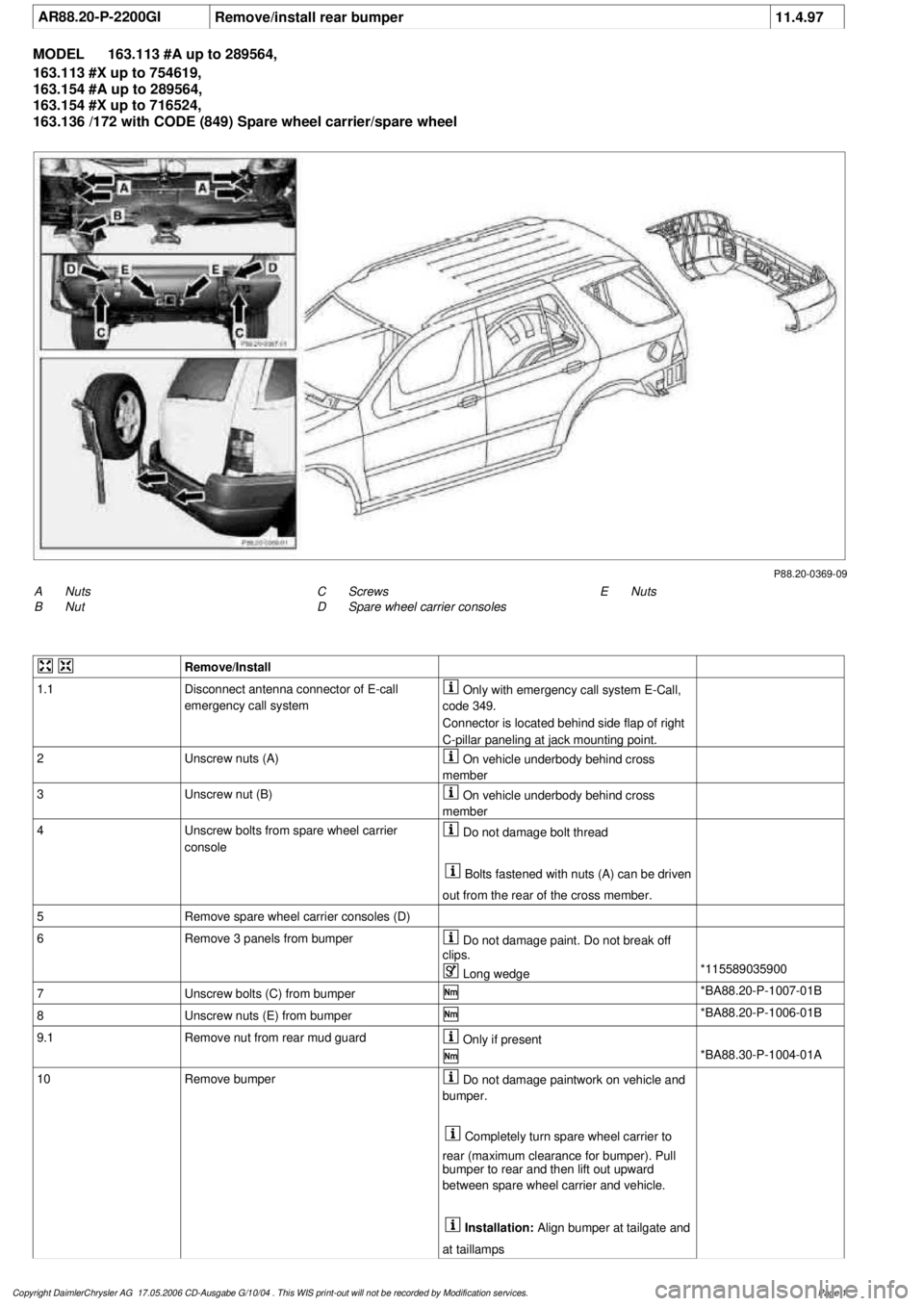
AR88.20-P-2200GI
Remove/install rear bumper
11.4.97
MODEL
163.113 #A up to 289564,
163.113 #X up to 754619,
163.154 #A up to 289564,
163.154 #X up to 716524,
163.136 /172 with CODE (849) Spare wheel carrier/spare wheel
P88.20-0369-09
A
Nuts
B
Nut
E
Nuts
C
Screws
D
Spare wheel carrier consoles
Remove/Install
1.1
Disconnect antenna connector of E-call
emergency call system
Only with emergency call system E-Call,
code 349.
Connector is located behind side flap of right
C-pillar paneling at jack mounting point.
2
Unscrew nuts (A)
On vehicle underbody behind cross
member
3
Unscrew nut (B)
On vehicle underbody behind cross
member
4
Unscrew bolts from spare wheel carrier
console
Do not damage bolt thread
Bolts fastened with nuts (A) can be driven
out from the rear of the cross member.
5
Remove spare wheel carrier consoles (D)
6
Remove 3 panels from bumper
Do not damage paint. Do not break off
clips.
Long wedge
*115589035900
7
Unscrew bolts (C) from bumper
*BA88.20-P-1007-01B
8
Unscrew nuts (E) from bumper
*BA88.20-P-1006-01B
9.1
Remove nut from rear mud guard
Only if present
*BA88.30-P-1004-01A
10
Remove bumper
Do not damage paintwork on vehicle and
bumper.
Completely turn spare wheel carrier to
rear (maximum clearance for bumper). Pull
bumper to rear and then lift out upward
between spare wheel carrier and vehicle.
Installation:
Align bumper at tailgate and
at taillamps
Copyright DaimlerChrysler AG 17.05.2006 CD-Ausgabe G/10/04 . This WIS print-out will not be recorde
d by Modification services.
Page 1
Page 1992 of 4133
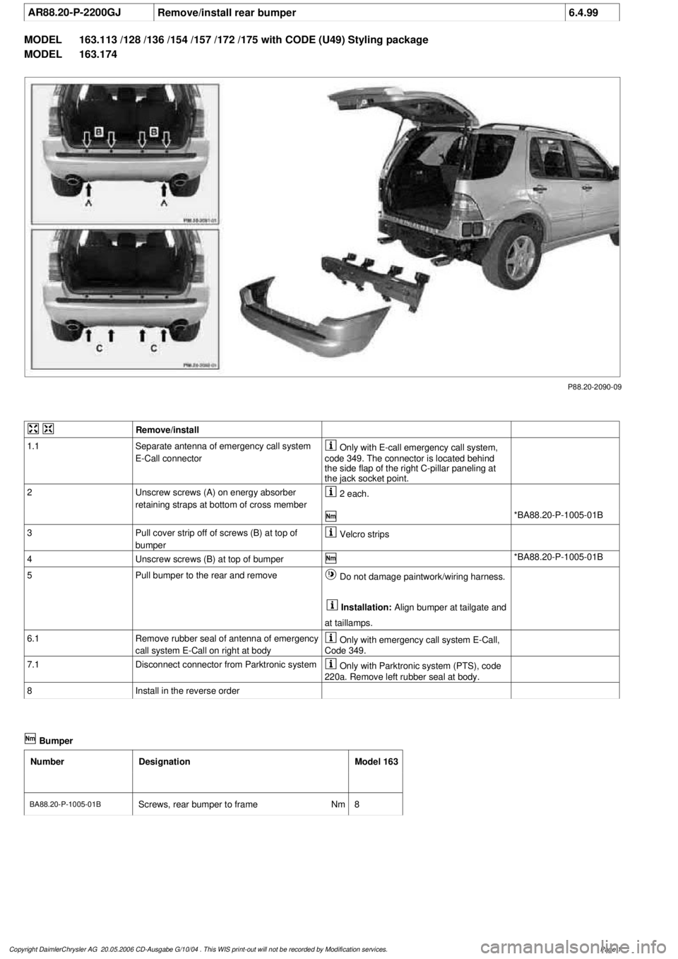
AR88.20-P-2200GJ
Remove/install rear bumper
6.4.99
MODEL
163.113 /128 /136 /154 /157 /172 /175 with CODE (U49) Styling package
MODEL
163.174
P88.20-2090-09
Remove/install
1.1
Separate antenna of emergency call system
E-Call connector
Only with E-call emergency call system,
code 349. The connector is located behind
the side flap of the right C-pillar paneling at
the jack socket point.
2
Unscrew screws (A) on energy absorber
retaining straps at bottom of cross member
2 each.
*BA88.20-P-1005-01B
3
Pull cover strip off of screws (B) at top of
bumper
Velcro strips
4
Unscrew screws (B) at top of bumper
*BA88.20-P-1005-01B
5
Pull bumper to the rear and remove
Do not damage paintwork/wiring harness.
Installation:
Align bumper at tailgate and
at taillamps.
6.1
Remove rubber seal of antenna of emergency
call system E-Call on right at body
Only with emergency call system E-Call,
Code 349.
7.1
Disconnect connector from Parktronic system
Only with Parktronic system (PTS), code
220a. Remove left rubber seal at body.
8
Install in the reverse order
Bumper
Number
Designation
Model 163
BA88.20-P-1005-01B
Screws, rear bumper to frame
Nm
8
Copyright DaimlerChrysler AG 20.05.2006 CD-Ausgabe G/10/04 . This WIS print-out will not be recorde
d by Modification services.
Page 1