1997 MERCEDES-BENZ ML500 ECU
[x] Cancel search: ECUPage 3433 of 4133
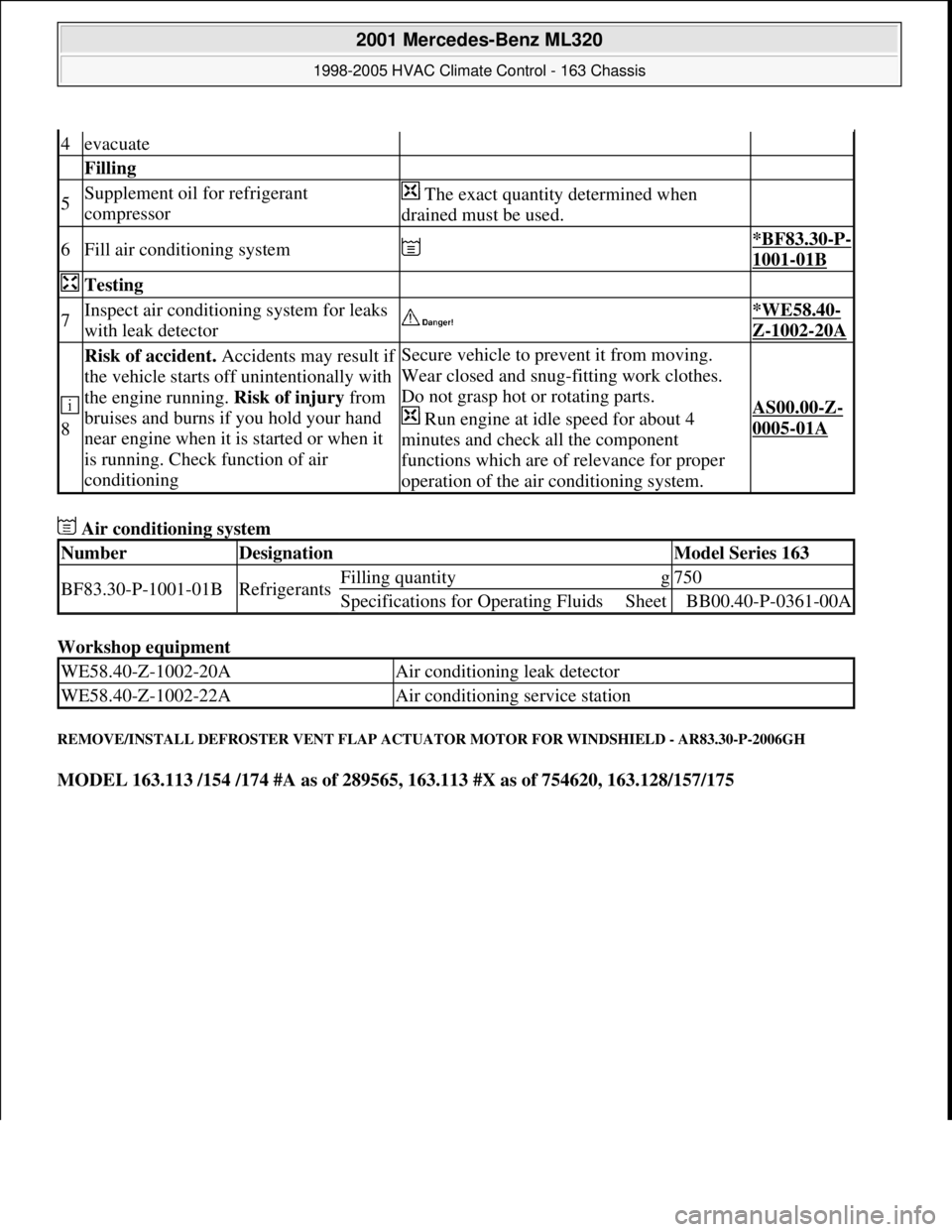
Air conditioning system
Workshop equipment
REMOVE/INSTALL DEFROSTER VENT FLAP ACTUATOR MOTOR FOR WINDSHIELD - AR83.30-P-2006GH
MODEL 163.113 /154 /174 #A as of 289565, 163.113 #X as of 754620, 163.128/157/175
4evacuate
Filling
5Supplement oil for refrigerant
compressor The exact quantity determined when
drained must be used.
6Fill air conditioning system *BF83.30-P-
1001-01B
Testing
7Inspect air conditioning system for leaks
with leak detector *WE58.40-
Z-1002-20A
8
Risk of accident. Accidents may result if
the vehicle starts off unintentionally with
the engine running. Risk of injury from
bruises and burns if you hold your hand
near engine when it is started or when it
is running. Check function of air
conditioningSecure vehicle to prevent it from moving.
Wear closed and snug-fitting work clothes.
Do not grasp hot or rotating parts.
Run engine at idle speed for about 4
minutes and check all the component
functions which are of relevance for proper
operation of the air conditioning system.
AS00.00-Z-
0005-01A
NumberDesignationModel Series 163
BF83.30-P-1001-01BRefrigerantsFilling quantityg750
Specifications for Operating FluidsSheetBB00.40-P-0361-00A
WE58.40-Z-1002-20AAir conditioning leak detector
WE58.40-Z-1002-22AAir conditioning service station
2001 Mercedes-Benz ML320
1998-2005 HVAC Climate Control - 163 Chassis
me
Saturday, October 02, 2010 3:23:18 PMPage 189 © 2006 Mitchell Repair Information Company, LLC.
Page 3457 of 4133
Air conditioning system
Refrigerant compressor
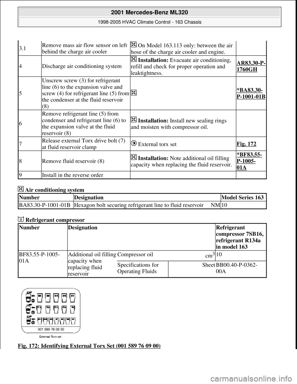
Fig. 172: Identifying External Torx Set (001 589 76 09 00)
3.1Remove mass air flow sensor on left
behind the charge air cooler On Model 163.113 only: between the air
hose of the charge air cooler and engine.
4Discharge air conditioning system
Installation: Evacuate air conditioning,
refill and check for proper operation and
leaktightness.AR83.30-P-
1760GH
5
Unscrew screw (3) for refrigerant
line (6) to the expansion valve and
screw (4) for refrigerant line (5) from
the condenser at the fluid reservoir
(8)
*BA83.30-
P-1001-01B
6
Remove refrigerant line (5) from
condenser and refrigerant line (6) to
the expansion valve at the fluid
reservoir (8)
Installation: Install new sealing rings
and moisten with compressor oil.
7Release external Torx drive bolt (7)
at fluid reservoir clamp External torx setFig. 172
8Remove fluid reservoir (8) Installation: Note additional oil filling
capacity when replacing the fluid reservoir.*BF83.55-
P-1005-
01A
9Install in the reverse order
NumberDesignationModel Series 163
BA83.30-P-1001-01BHexagon bolt securing refrigerant line to fluid reservoirNM10
NumberDesignationRefrigerant
compressor 7SB16,
refrigerant R134a
in model 163
BF83.55-P-1005-
01AAdditional oil filling
capacity when
replacing fluid
reservoirCompressor oilcm3 10
Specifications for
Operating FluidsSheetBB00.40-P-0362-
00A
2001 Mercedes-Benz ML320
1998-2005 HVAC Climate Control - 163 Chassis
me
Saturday, October 02, 2010 3:23:18 PMPage 213 © 2006 Mitchell Repair Information Company, LLC.
Page 3460 of 4133
Air conditioning system
Refrigerant compressor
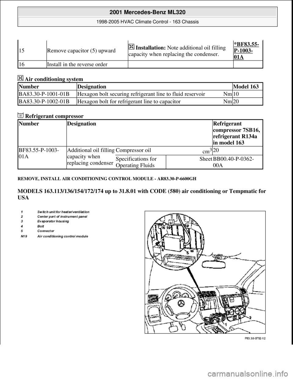
REMOVE, INSTALL AIR CONDITIONING CONTROL MODULE - AR83.30-P-6600GH
MODELS 163.113/136/154/172/174 up to 31.8.01 with CODE (580) air conditioning or Tempmatic for
USA
15Remove capacitor (5) upward Installation: Note additional oil filling
capacity when replacing the condenser.*BF83.55-
P-1003-
01A
16Install in the reverse order
NumberDesignationModel 163
BA83.30-P-1001-01BHexagon bolt securing refrigerant line to fluid reservoirNm10
BA83.30-P-1002-01BHexagon bolt for refrigerant line to capacitorNm20
NumberDesignationRefrigerant
compressor 7SB16,
refrigerant R134a
in model 163
BF83.55-P-1003-
01AAdditional oil filling
capacity when
replacing condenserCompressor oilcm3 20
Specifications for
Operating FluidsSheetBB00.40-P-0362-
00A
2001 Mercedes-Benz ML320
1998-2005 HVAC Climate Control - 163 Chassis
me
Saturday, October 02, 2010 3:23:18 PMPage 216 © 2006 Mitchell Repair Information Company, LLC.
Page 3473 of 4133
AC compressor
Refrigerant compressor
2Remove poly V-belt AR13.22-P-
1202B
3
Unscrew hexagon socket head screw
(1) securing low-pressure refrigerant
line (2) to refrigerant compressor (6) Detach low-pressure refrigerant line (2)
from refrigerant compressor (6).
Installation: Install new sealing rings
and moisten with compressor oil.
*BA83.55-
P-1002-01A
4
Unscrew hexagon socket head screw
(3) securing high-pressure refrigerant
line (4) to refrigerant compressor (6)
*BA83.55-
P-1002-01A
5
Detach refrigerant compressor
connector (A9x1) at refrigerant
compressor (6) Installation: Install new sealing rings
and moisten with compressor oil.
6
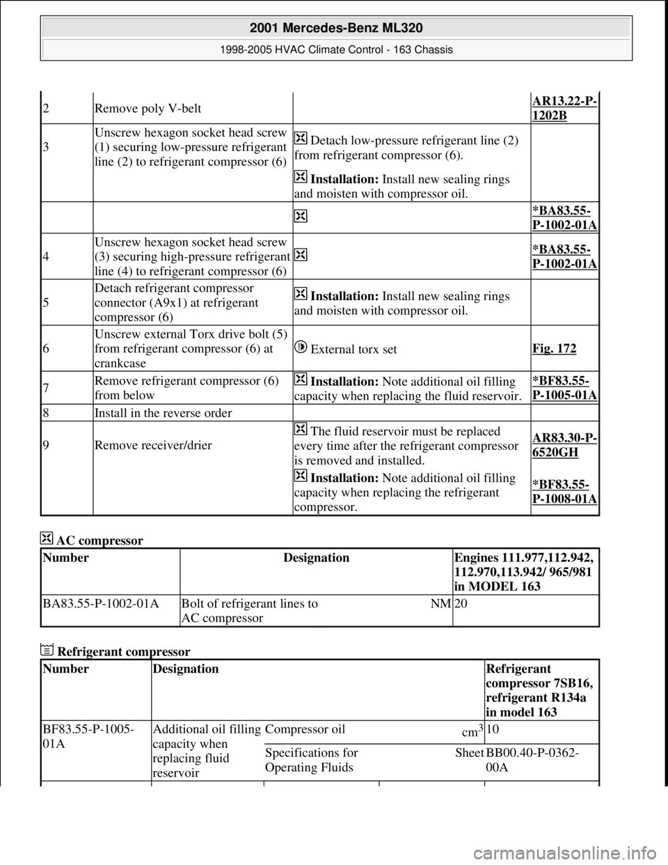
Unscrew external Torx drive bolt (5)
from refrigerant compressor (6) at
crankcase
External torx setFig. 172
7Remove refrigerant compressor (6)
from below Installation: Note additional oil filling
capacity when replacing the fluid reservoir.*BF83.55-
P-1005-01A
8Install in the reverse order
9Remove receiver/drier
The fluid reservoir must be replaced
every time after the refrigerant compressor
is removed and installed.AR83.30-P-
6520GH
Installation: Note additional oil filling
capacity when replacing the refrigerant
compressor.*BF83.55-
P-1008-01A
NumberDesignationEngines 111.977,112.942,
112.970,113.942/ 965/981
in MODEL 163
BA83.55-P-1002-01ABolt of refrigerant lines to
AC compressorNM20
NumberDesignationRefrigerant
compressor 7SB16,
refrigerant R134a
in model 163
BF83.55-P-1005-
01AAdditional oil filling
capacity when
replacing fluid
reservoirCompressor oilcm3 10
Specifications for
Operating FluidsSheetBB00.40-P-0362-
00A
2001 Mercedes-Benz ML320
1998-2005 HVAC Climate Control - 163 Chassis
me
Saturday, October 02, 2010 3:23:19 PMPage 229 © 2006 Mitchell Repair Information Company, LLC.
Page 3499 of 4133
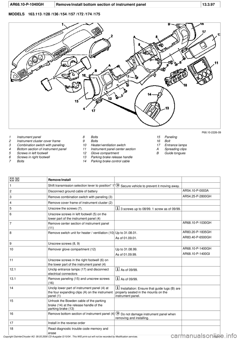
AR68.10-P-1040GH
Remove/install bottom section of instrument panel
13.3.97
MODELS
163.113 /128 /136 /154 /157 /172 /174 /175
P68.10-2226-09
1
Instrument panel
2
Instrument cluster cover frame
3
Combination switch with paneling
4
Bottom section of instrument panel
5
Screws in left footwell
6
Screws in right footwell
7
Bolts
15
Paneling
16
Bolt
17
Entrance lamps
A
Spreading clips
B
Guide tongues
8
Bolts
9
Bolts
10
Heater/ventilation switch
11
Instrument panel center section
12
Glove compartment
13
Parking brake release handle
14
Parking brake control cable
Remove/install
1
Shift transmission selection lever to position" 1"
Secure vehicle to prevent it moving away.
2
Disconnect ground cable of battery
AR54.10-P-0003A
3
Remove combination switch with paneling (3)
AR54.25-P-2800GH
4
Remove cover frame of instrument cluster (2)
5
Unscrew the screws (7).
3 screws up to 08/99. 1 screw as of 09/99.
6
Unscrew screws in left footwell (5) on the
lower part of the instrument panel (4)
7
Remove center section of instrument panel
(11)
AR68.10-P-1030GH
8
Remove switch unit for heater / ventilation (10)
Up to 31.08.01.
AR83.20-P-1835GH
As of 01.09.01.
AR83.40-P-6500GH
9
Unscrew screws (8, 9)
10
Remover glove compartment (12)
Up to 31.08.99.
AR68.10-P-1400GH
As of 01.09.99.
AR68.10-P-1400GI
11
Unscrew screws in the right footwell (6) on
the lower part of the instrument panel (4)
12.1
Unclip entrance lamps (17) and disconnect
electrical connectors
As of 09/99.
13.1
Remove paneling (15) and unscrew screws
(16)
As of 09/99.
14
Unclip lower part of instrument panel (4) at
the four expanding clips (A) on the instrument
panel (1)
Installation: Ensure that guide lugs (B) are
properly seated in the mounts on the
instrument panel.
15
Unhook the Bowden cable of the parking
brake (14) at the release handle of the
parking brake (13)
16
Remove bottom section of instrument panel (4)
Do not damage instrument panel when
removing and installing.
17
Install in the reverse order
18
Read diagnostic trouble code memory and
erase
Copyright DaimlerChrysler AG 09.05.2006 CD-Ausgabe G/10/04 . This WIS print-out will not be recorde
d by Modification services.
Page 1
Page 3518 of 4133
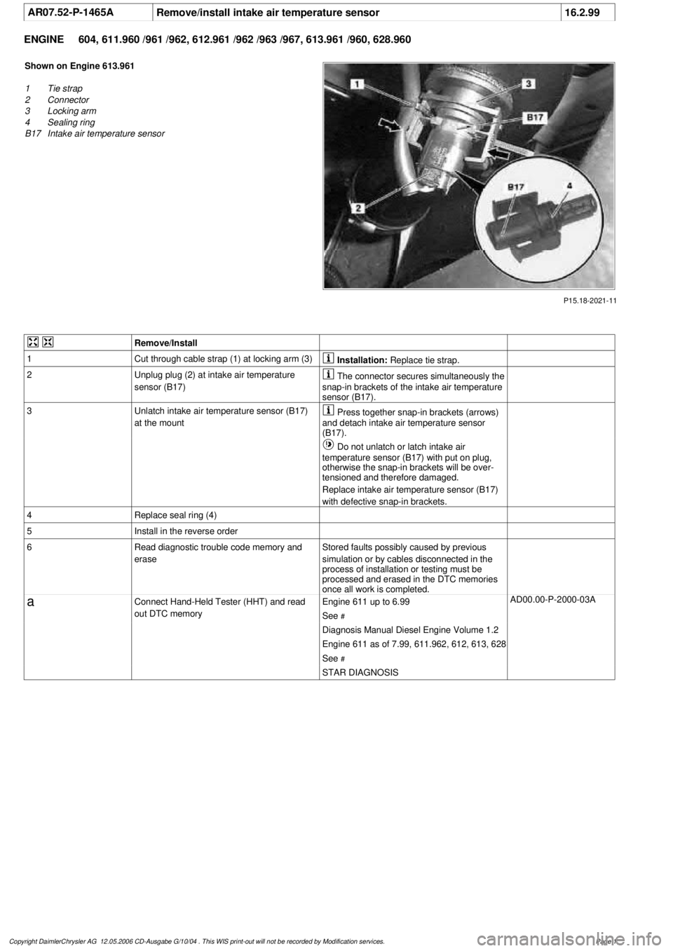
AR07.52-P-1465A
Remove/install intake air temperature sensor
16.2.99
ENGINE
604, 611.960 /961 /962, 612.961 /962 /963 /967, 613.961 /960, 628.960
P15.18-2021-11
Shown on Engine 613.961
1
Tie strap
2
Connector
3
Locking arm
4
Sealing ring
B17
Intake air temperature sensor
Remove/Install
1
Cut through cable strap (1) at locking arm (3)
Installation:
Replace tie strap.
2
Unplug plug (2) at intake air temperature
sensor (B17)
The connector secures simultaneously the
snap-in brackets of the intake air temperature
sensor (B17).
3
Unlatch intake air temperature sensor (B17)
at the mount
Press together snap-in brackets (arrows)
and detach intake air temperature sensor
(B17).
Do not unlatch or latch intake air
temperature sensor (B17) with put on plug,
otherwise the snap-in brackets will be over-
tensioned and therefore damaged.
Replace intake air temperature sensor (B17)
with defective snap-in brackets.
4
Replace seal ring (4)
5
Install in the reverse order
6
Read diagnostic trouble code memory and
erase
Stored faults possibly caused by previous
simulation or by cables disconnected in the
process of installation or testing must be
processed and erased in the DTC memories
once all work is completed.
a
Connect Hand-Held Tester (HHT) and read
out DTC memory
Engine 611 up to 6.99
See
#
AD00.00-P-2000-03A
Diagnosis Manual Diesel Engine Volume 1.2
Engine 611 as of 7.99, 611.962, 612, 613, 628
See
#
STAR DIAGNOSIS
Copyright DaimlerChrysler AG 12.05.2006 CD-Ausgabe G/10/04 . This WIS print-out will not be recorde
d by Modification services.
Page 1
Page 3538 of 4133
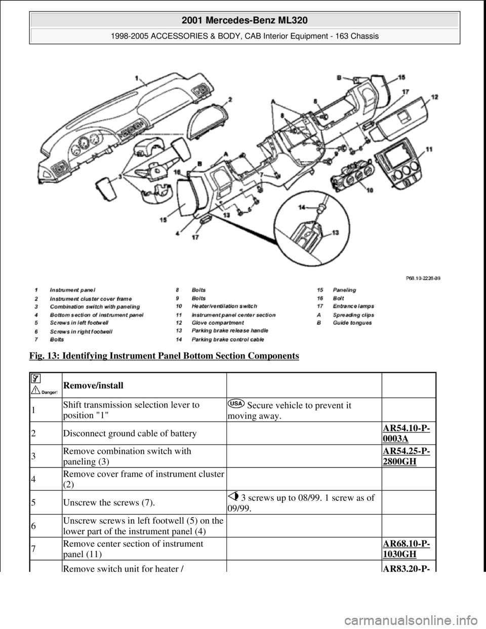
Fig. 13: Identifying Instrument Panel Bottom Section Components
Remove/install
1Shift transmission selection lever to
position "1" Secure vehicle to prevent it
moving away.
2Disconnect ground cable of battery AR54.10-P-
0003A
3Remove combination switch with
paneling (3) AR54.25-P-
2800GH
4Remove cover frame of instrument cluster
(2)
5Unscrew the screws (7). 3 screws up to 08/99. 1 screw as of
09/99.
6Unscrew screws in left footwell (5) on the
lower part of the instrument panel (4)
7Remove center section of instrument
panel (11) AR68.10-P-
1030GH
Remove switch unit for heater / AR83.20-P-
2001 Mercedes-Benz ML320
1998-2005 ACCESSORIES & BODY, CAB Interior Equipment - 163 Chassis
me
Saturday, October 02, 2010 3:35:21 PMPage 20 © 2006 Mitchell Repair Information Company, LLC.
Page 3575 of 4133
Safety belts/emergency tensioning retractors
Luggage nets
Child seats
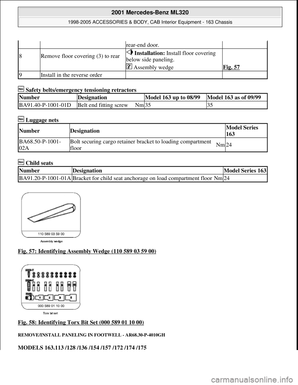
Fig. 57: Identifying Assembly Wedge (110 589 03 59 00)
Fig. 58: Identifying Torx Bit Set (000 589 01 10 00)
REMOVE/INSTALL PANELING IN FOOTWELL - AR68.30-P-4010GH
MODELS 163.113 /128 /136 /154 /157 /172 /174 /175
rear-end door.
8Remove floor covering (3) to rear Installation: Install floor covering
below side paneling.
Assembly wedgeFig. 57
9Install in the reverse order
NumberDesignationModel 163 up to 08/99Model 163 as of 09/99
BA91.40-P-1001-01DBelt end fitting screwNm3535
NumberDesignationModel Series
163
BA68.50-P-1001-
02ABolt securing cargo retainer br acket to loading compartment
floorNm24
NumberDesignationModel Series 163
BA91.20-P-1001-01ABracket for child seat anchorage on load compartment floorNm24
2001 Mercedes-Benz ML320
1998-2005 ACCESSORIES & BODY, CAB In terior Equipment - 163 Chassis
me
Saturday, October 02, 2010 3:35:22 PMPage 57 © 2006 Mitchell Repair Information Company, LLC.