1997 MERCEDES-BENZ ML500 airbag
[x] Cancel search: airbagPage 2118 of 4133
SI72.10-P-0002GH
Service Information: Modification of the front door
6.5.03
MODEL
163.113 /128 /136 /154 /157 /172 /174 /175
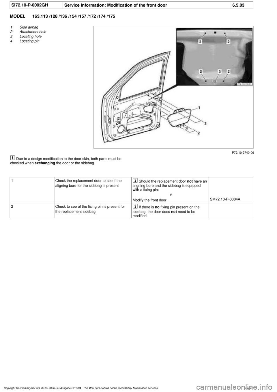
P72.10-2740-06
1
Side airbag
2
Attachment hole
3
Locating hole
4
Locating pin
Due to a design modification to the door skin, both parts must be
checked when
exchanging
the door or the sidebag.
1
Check the replacement door to see if the
aligning bore for the sidebag is present
Should the replacement door
not
have an
aligning bore and the sidebag is equipped
with a fixing pin:
#
Modify the front door
SM72.10-P-0004A
2
Check to see of the fixing pin is present for
the replacement sidebag
If there is
no
fixing pin present on the
sidebag, the door does
not
need to be
modified.
Copyright DaimlerChrysler AG 09.05.2006 CD-Ausgabe G/10/04 . This WIS print-out will not be recorde
d by Modification services.
Page 1
Page 2123 of 4133
SM72.10-P-0004A
Modify front door
6.5.03
MODEL
163.113 /128 /136 /154 /157 /172 /174 /175
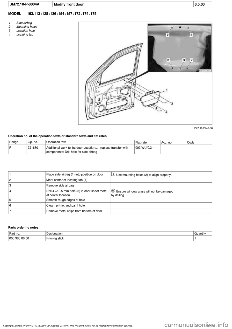
P72.10-2740-06
1
Side airbag
2
Mounting holes
3
Location hole
4
Locating tab
Operation no. of the operation texts or standard texts and flat rates
Range
Op. no.
Operation text
Flat rate
Acc. no.
Code
P
721680
Additional work to 1st door Location:.... replace transfer with
components: Drill hole for side airbag
003 WU/0.3 h
------
1
Place side airbag (1) into position on door
Use mounting holes (2) to align properly.
2
Mark center of locating tab (4)
3
Remove side airbag
4
Drill
4
=10.5 mm hole (3) in door sheet metal
at center location
Ensure window glass will not be damaged
by drilling.
5
Smooth rough edges of hole
6
Clean, prime, and paint hole
7
Remove metal chips from bottom of door
Parts ordering notes
Part no.
Designation
Quantity
000 986 06 50
Priming stick
1
Copyright DaimlerChrysler AG 09.05.2006 CD-Ausgabe G/10/04 . This WIS print-out will not be recorde
d by Modification services.
Page 1
Page 2524 of 4133
brake hoses *BA42.10-P-1001-04A
Ring wrench socketFig. 5
5Unbolt propeller shaft at
flange on front axle
transmission *BA41.20-P-1001-01A
6Remove left and right
front springs AR32.20-P-0200GH
7.1Remove lower engine
compartment panelingModel
163.157 /172 /174 /175AR61.20-P-1105GH
Model 163.113/ 128AR94.30-P-5400GH
8Detach torsion bar (28) at
vehicle frame *BA32.20-P-1001-02G
9Detach upper transverse
control arm (6) from
vehicle frame Installation: Tighten
new nuts slightly. Tighten
bolt fully only when
vehicle is on its wheels and
ready to drive.
*BA33.20-P-1006-01D
10Detach bracket for oil
lines from transmission to
oil cooler on front axle
carrier
11Unclip brake line at rear
of front-axle
crossmember
12.1Remove vehicle level
controller connecting rod
(95b) at lower transverse
control arm on right Vehicles with xenon
headlamps.
13Extract fluid from power
steering pump reservoir Hand pumpFig. 6
14Turn steering wheel to
center position (front
wheels in straight-ahead
position) and secureThe steering wheel must
not be turned when the
steering coupling has been
removed. This will damage
the fanfare horns and airbag
clock spring contact
beyond repair.
Remove ignition key
and turn steering wheel so
that it locks.
15.1Detach plug-in connector
for speed-sensitive power
steering to timing case Vehicles with speed-
sensitive power steering
only.
2001 Mercedes-Benz ML320
1998-2005 DRIVELINE/AXLES Front Axle - 163 Chassis
me
Saturday, October 02, 2010 3:38:21 PMPage 5 © 2006 Mitchell Repair Information Company, LLC.
Page 2646 of 4133
1998-2005 GENINFO
Overall vehicle - 163 Chassis
GENERAL INFORMATION
NOTES ON SELF-LOCKING NUTS AND BOLTS - AH00.00-N-0001-01A
All models
Important repair information
Bolts with locking splines, micro-encapsulated bolts and self-locking nuts must always be replaced after
being used once.
There is an increased risk of injury when unscrewing micro-encapsulated bolts due to the sudden breakaway
torque.
Before new micro-encapsulated bolts are screwed in, the mating thread must be re-cut in order to remove all the
residue of the old bolt locking compound.
MEASURES FOR PREVENTING DAMAGE TO VEHICLES OR COMPONENTS WHEN PERFORMING ARC WELDING
WORK - AH00.00-N-0005-01A
All models
The following measures must be taken before welding in order to prevent damage to various vehicle
components:
1 Have fire extinguishers at the ready.
2 The negative terminal of the battery must be disconnected and covered up.
3 In vehicle with airbags the red, 12-pin test connection/plug-in connection must be disconnected no
sooner than two seconds after the battery has been disconnected (risk of unwanted activation).
6 Attach protective shields to prevent flying sparks and radiated heat in endangered areas.
7 Do not touch electronics housings or electrical cables with the welding electrode or the welder's ground
connection.
8 If two parts are being welded together, both parts must be attached to the welder's negative clamp.
9 Make direct connection between the electrical welder's ground connection and the part being welded.
Ensure that there are no electrically insulating parts between the ground connection and the welding
point.
10 Protect or remove any parts that are sensitive to heat such as plastic cables.
11 Remove electrical cables that are laid in cavities and/or pipelines, covered containers and electrical
components from the danger area before welding.
12 If possible, the points where the welded part is being attached to the vehicle and the ground terminal is
attached to the electrical welder must be bare; remove all traces of paint, corrosion, oil, grease and
2004 Mercedes-Benz ML350
1998-2005 GENINFO Overall vehicle - 163 Chassis
2004 Mercedes-Benz ML350
1998-2005 GENINFO Overall vehicle - 163 Chassis
me
Saturday, October 02, 2010 3:47:43 PMPage 1 © 2006 Mitchell Repair Information Company, LLC.
me
Saturday, October 02, 2010 3:48:01 PMPage 1 © 2006 Mitchell Repair Information Company, LLC.
Page 2661 of 4133
NOTES ON REPLACING SAFETY - RELEVANT COMPONENTS - AH00.19-P-1000-02A
General
With the approval of repair solutions for wiring harnesses (in particular airbag, side airbag, window airbag,
emergency tensioning retractor wiring harness), it is necessary to introduce a modified ordering routine for
procuring safety-relevant components. The order formalities are by and large the same as those which are
already familiar from theft-relevant components.
Procedure
It is only possible to order safety-relevant components by stating the vehicle ident number (refer parts order
note on the parts microfiche).
The repair orders and invoices should be filed in the usual way.
All orders received for safety-relevant components are additionally automatically documented in Fdok.
ADVANTAGES OF REPAIRING WIRING HARNESSES - AH00.19-P-1000-03A
Model 124, 126, 129, 140, 163, 164, 168, 169, 170, 171, 199, 202, 203, 208, 209, 210, 211, 215, 216, 219, 220,
221, 230, 240, 245, 251, 414, 461, 463
Advantages of repairing wiring harnesses
Wiring harnesses are essentially repaired to reduce repair costs.
If repairs are carried out properly, there is no difference in function or quality between the repaired wiring
harness and a brand new wiring harness.
Repairing wiring harnesses helps to save resources.
This also complies with the "Technical Alliance Center" requirements for less dismantling and
installation cost.
REPAIR METHODS FOR WIRING HARNESSES - AH00.19-P-1000-04A
Model 124, 126, 129, 140, 163, 164, 168, 169, 170, 171, 199, 202, 203, 208, 209, 210, 211, 215, 216, 219, 220,
221, 230, 240, 245, 251, 414, 461, 463
Repair method summary
The following methods have been approved by DaimlerChrysler for repairing wiring harnesses in Mercedes-
Benz passenger cars:
Repair methods:
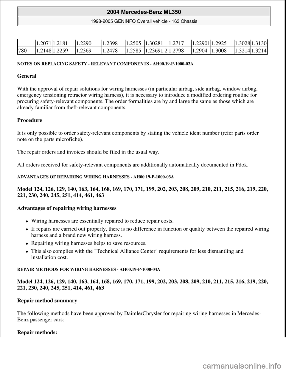
1.20711.21811.22901.23981.25051.302811.27171.229011.29251.30281.3130
7801.21481.22591.23691.24781.25851.23691.21.27981.29041.30081.32141.3214
2004 Mercedes-Benz ML350
1998-2005 GENINFO Overall vehicle - 163 Chassis
me
Saturday, October 02, 2010 3:47:44 PMPage 16 © 2006 Mitchell Repair Information Company, LLC.
Page 2669 of 4133
Model 124, 126, 129, 140, 163, 164, 168, 169, 170, 171, 199, 202, 203, 208, 209, 210, 211, 215, 216, 219, 220,
221, 230, 240, 245, 251, 414, 461, 463
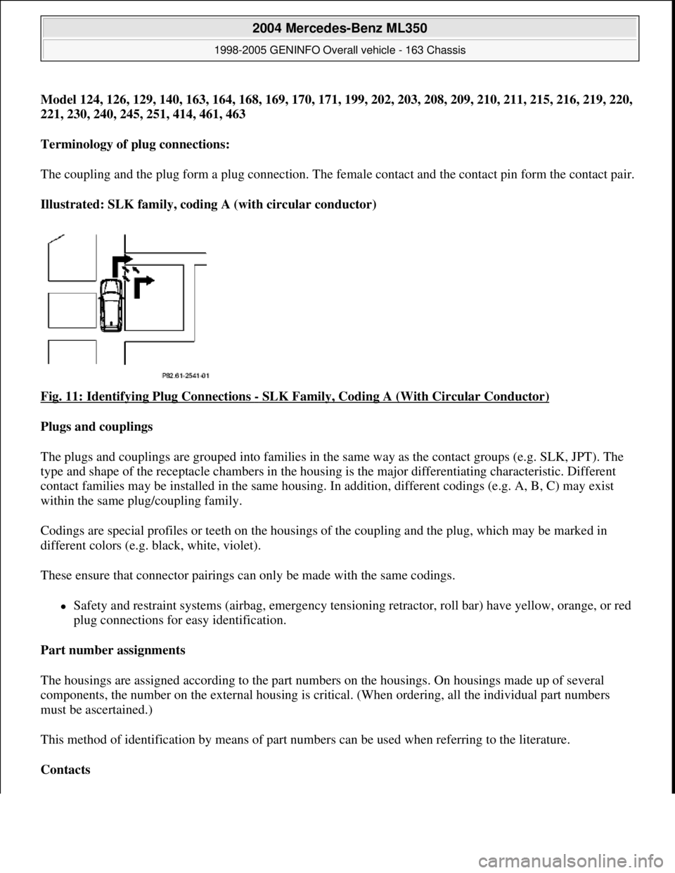
Terminology of plug connections:
The coupling and the plug form a plug connection. The female contact and the contact pin form the contact pair.
Illustrated: SLK family, coding A (with circular conductor)
Fig. 11: Identifying Plug Connections
- SLK Family, Coding A (With Circular Conductor)
Plugs and couplings
The plugs and couplings are grouped into families in the same way as the contact groups (e.g. SLK, JPT). The
type and shape of the receptacle chambers in the housing is the major differentiating characteristic. Different
contact families may be installed in the same housing. In addition, different codings (e.g. A, B, C) may exist
within the same plug/coupling family.
Codings are special profiles or teeth on the housings of the coupling and the plug, which may be marked in
different colors (e.g. black, white, violet).
These ensure that connector pairings can only be made with the same codings.
Safety and restraint systems (airbag, emergency tensioning retractor, roll bar) have yellow, orange, or red
plug connections for easy identification.
Part number assignments
The housings are assigned according to the part numbers on the housings. On housings made up of several
components, the number on the external housing is critical. (When ordering, all the individual part numbers
must be ascertained.)
This method of identification by means of part numbers can be used when referring to the literature.
Contacts
2004 Mercedes-Benz ML350
1998-2005 GENINFO Overall vehicle - 163 Chassis
me
Saturday, October 02, 2010 3:47:44 PMPage 24 © 2006 Mitchell Repair Information Company, LLC.
Page 2670 of 4133
A distinction is made between the contact pin and the female contact. Each contact pin and each female contact
can be clearly assigned to one group or "family" (e.g. SLK, JPT). Within these families distinctions are made
according to the cable cross section and whether there is single-strand insulation for watertight connections. The
contacts are also distinguished by their coating (tin, gold or silver).
The contacts are fastened to the cables by means of crimping. ?
Crimp connections
These are used to attach the female contacts or contact pins to the cable. Each contact type must be crimped
with the aid of specifically assigned die sets using a pair of pliers. Determining factors: contact family, size of
cable cross section, with or without single-strand insulation.
Only lines up to 4 mm shall be crimped.
Unpinning
This requires a release tool appropriate to the contact family in order to remove female contacts and contact pins
from plugs and couplings.
On some plugs and couplings the housings must first be disassembled and unlocked (secondary release)
according to the instructions before the actual unpinning.
Contact materials
The contacts used in the interior of the vehicle are primarily tin/tin combinations. Those used on the exterior
and in the splash zone are generally silver/silver. Safety systems (particularly the airbag) are equipped with
gold/gold contacts.
Only "identical" contact pairings are permitted for repair work.
NOTES ON SOFT SOLDERING - AH00.19-P-1000-07A
Model 124, 126, 129, 140, 163, 164, 168, 169, 170, 171, 199, 202, 203, 208, 209, 210, 211, 215, 216, 219, 220,
221, 230, 240, 245, 251, 414, 461, 463
General information
Soft-soldering is a process for creating an inseparable join between two or more metal parts using additional
metals (e.g. soldering tin). The solder melting temperature lies below the melting temperature of the metals to
be joined and is lower than 450°C.
The connection is created by wetting the joint locations with hot liquid solder, without melting the parts to be
joined.
The joining procedure is assisted by using a flux, which releases surface oxides on the parts to be joined,
eliminatin
g and preventing surface films (e.g. greases).
2004 Mercedes-Benz ML350
1998-2005 GENINFO Overall vehicle - 163 Chassis
me
Saturday, October 02, 2010 3:47:44 PMPage 25 © 2006 Mitchell Repair Information Company, LLC.
Page 2672 of 4133
Plugs and couplings. with yellow, orange or red housing colors are reserved for safety and restraint systems
(SRS) and roll bars.
Observe the following when repairing couplings for squibs (SRS systems):
The repair area must be between 100 mm and 1000 mm behind the squib. Cables which have already been
repaired are provided with a yellow marking. This is to be applied retroactively to repair lines without color
marking.
Carry out the first repair as close to the plug as possible. In the case of subsequent repairs the old soldered
connectors should be removed and the new ones should be attached behind them, the wiring harness should be
replaced if necessary.
Before cutting through the lines it is absolutely essential to assign the lines to the corresponding pins in
accordance with the wiring diagram. Do not mix up the pin assignment.
The line colors of the repair kit may deviate from the original fitting
Screened lines and light plastic-sheathed cable must never be repaired
In general the following applies to cable repair:
If more than ten lines per branch-off line are damaged, the wiring harness module must be replaced.
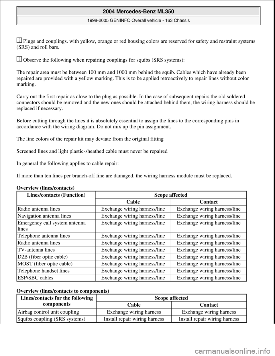
Overview (lines/contacts)
Overview (lines/contacts to components)
Lines/contacts (Function)Scope affected
CableContact
Radio antenna linesExchange wiring harness/lineExchange wiring harness/line
Navigation antenna linesExchange wiring harness/lineExchange wiring harness/line
Emergency call system antenna
linesExchange wiring harness/lineExchange wiring harness/line
Telephone antenna linesExchange wiring harness/lineExchange wiring harness/line
Radio antenna linesExchange wiring harness/lineExchange wiring harness/line
TV-antenna linesExchange wiring harness/lineExchange wiring harness/line
D2B (fiber optic cable)Exchange wiring harness/lineExchange wiring harness/line
MOST (fiber optic cable)Exchange wiring harness/lineExchange wiring harness/line
Telephone handset linesExchange wiring harness/lineExchange wiring harness/line
ESP/SBC cablesExchange wiring harness/lineExchange wiring harness/line
Lines/contacts for the following
componentsScope affected
CableContact
Airbag control unit couplingExchange wiring harnessExchange wiring harness
Squibs coupling (SRS systems)Install repair wiring harnessInstall repair wiring harness
2004 Mercedes-Benz ML350
1998-2005 GENINFO Overall vehicle - 163 Chassis
me
Saturday, October 02, 2010 3:47:44 PMPage 27 © 2006 Mitchell Repair Information Company, LLC.