1997 MERCEDES-BENZ ML430 diagnostics
[x] Cancel search: diagnosticsPage 203 of 4133
153 Tele Aid
Te ch n ica l
data Instruments
and controlsOperationDrivingInstrument
cluster displayPractical hints Car care Index When the connection is established, the message
“ROADSIDE ASSISTANCE – CALL CONNECTED”
appears in the MCS display. The Tele Aid system will
transmit data generating the vehicle identification
number, model, color and location (subject to
availability of cellular and GPS signals).
While the call is connected, you can change to
navigation menu by pressing NAVI button on the MCS.
A voice connection between the Roadside Assistance
dispatcher and the occupants of the vehicle will be
established. When a voice connection is established the
audio system mutes and the message “TELE AID –
ROADSIDE ASSISTANCE CALL ACTIVE” appears in the
MCS display. The nature of the need for assistance can
then be described. The Mercedes-Benz Roadside
assistance dispatcher will either dispatch a qualified
Mercedes-Benz technician or arrange to tow your
vehicle to the nearest Mercedes-Benz Center. For
services such as labor and/or towing charges may apply.
Refer to the Roadside Assistance manual for more
information.These programs are only available in the USA:
•Sign and Drive services: Services such as jump start,
a few gallons of fuel or the replacement of a f lat tire
with the vehicle spare tire are obtainable,
•Remote Vehicle Diagnostics: This function permits
the Mercedes-Benz Roadside Assistance dispatcher
to download malfunction codes and actual vehicle
data.
Notes:
The indicator lamp in the Roadside Assistance
button• remains illuminated in red for
approximately 10 seconds during the system self-check
after turning key in steering lock to position 2 (together
with the “SOS” button and the Information
button¡).
See system self-check on page 148 when the indicator
lamp does not light up in red or stay on longer than
approximately 10 seconds.
Page 367 of 4133
Fig. 1: Locating Restraint System Components (2000 E Class Shown; Others Are Similar)
Courtesy of MERCEDES-BENZ OF NORTH AMERICA.
SERVICING
SRS AIR BAG label on driver-side door latch post indicates SRS replacement date for driver and passenger air
bag units. All SRS components must be thoroughly insp ected, including wiring harness. Before component
replacement, check for SRS fault codes by performing system operation check. See SYSTEM OPERATION
CHECK . SRS service life is 10 years from manufactured date, or 10 years from SRS replacement date after
accident related repairs are completed.
SYSTEM OPERATION CHECK
SRS warning light indicates air ba g and Emergency Tensioning Retracto r (ETR) system readiness. Turn
ignition on. SRS warning light will illuminate, then turn off after approximately 4-20 seconds indicating system
is functioning properly. If SRS warning light does not illuminate, illuminates while driving or is continuously
illuminated, there is a system faul t. Repair malfunctioning system. See DIAGNOSTICS
.
AIR BAG SAFETY PRECAUTIONS
Observe following precautions when working with air bag systems:
When working around steering column components and be fore any repairs are performed, disable air bag
system. See DISABLING & ACTIVATING AIR BAG SYSTEM
.
Before straightening any damage to body, or before performing electrical arc-welding, disable air bag
system. See DISABLING & ACTIVATING AIR BAG SYSTEM
.
Always wear safety glasses and gloves when ha ndling a deployed air bag module. Air bag module may
contain sodium hydroxide deposits wh ich are irritating to the skin.
DO NOT repair any portion of SRS wiring harness.
Always handle air bag module with trim cover away from your body. Always place air bag module on
workbench with trim cover up, away from loose objects.
DO NOT expose any SRS component to temp eratures in excess of 212 F (100 C).
DO NOT expose any SRS component to cleaning agen ts such as solvents, gasoline, lye, etc.
DO NOT connect Hand-Held Tester (6511 0001 99) to Data Link Connector (DLC) with ignition on.
Damage to HHT may result.
DO NOT connect HHT (6511 0001 99) to vehicle if a battery charger is connected to vehicle battery.
Damage to HHT may result.
ADJUSTMENTS
If fixing screws were not used durin g clockspring removal or clockspring was rotated during removal, turn
clockspring clockwise until resistance is detectable. Turn clockspring counterclockwise 2-2.5 turns until fixing
screws can be unscrewed holdi ng clockspring in this position.
DISABLING & ACTIVATI NG AIR BAG SYSTEM
2001 Mercedes-Benz ML320
2000-01 ACCESSORIES/SAFETY EQUIPMENT Merc edes-Benz - Air Bag Restraint Systems
me
Saturday, October 02, 2010 3:44:45 PMPage 3 © 2006 Mitchell Repair Information Company, LLC.
Page 379 of 4133
module.
2. To install air bag module, reverse removal procedur e. Activate air bag system. Perform system operation
check to ensure system is functioning properly. See SYSTEM OPERATION CHECK
.
Removal & Installation (SLK 320)
1. Before proceeding, See AIR BAG SAFETY PRECAUTIONS . Disable air bag system. See
DISABLING & ACTIVATI NG AIR BAG SYSTEM
. Remove ignition key. Remove top section of
instrument panel. Fold vapor barrier toward front to reveal 2 screws. Disconnect passenger-side air bag
module connector. Remove 4 screws and passenger-side air bag module.
2. To install air bag module, reverse removal procedur e. Activate air bag system. Perform system operation
check to ensure system is functioning properly. See SYSTEM OPERATION CHECK
.
DIAGNOSTICS
Before proceeding, see AIR BAG SAFETY PRECAUTIONS
. The SRS control module is capable of
diagnosing air bag system components and ETR components. If a fault is detected by the SRS control module
or system is malfunctioning, SRS warning light will do one or more of the following:
SRS warning light goes out after 2 minutes. System fault is noted, however occupant protection is not
affected. See RETRIEVING FAULT CODES
.
SRS warning light illuminates cont inuously. System is faulty which may result in a non deployment or
false deployment. See RETRIEVING FAULT CODES
.
SRS warning light blinks continuous ly. Control module has been replaced without setting control module
parameters.
RETRIEVING FAULT CODES
1. Check vehicle fuses. Replace any blown fuses as nece ssary. Ensure vehicle battery voltage is 11 volts or
more. Ensure SRS warning light functions. Turn i gnition off. Connect Hand-Held Tester (HHT) (965 589
00 01) to Data Link Connector (DLC).
2. DLC is located in right rear corner of engine comp artment. It may be necessary to use Adapter (965 589
00 40 or 965 589 00 50) to connect HHT to DLC. Afte r HHT displays module number and version, press
return key to start diagnosis. Us ing HHT, follow HHT prompts to re trieve SRS fault codes. For SRS
control modules beginning with number 000, fault c ode 1 is valid. For SRS control modules beginning
with number 001, fault code 2 is valid. See Fig. 6
.
3. HHT will display a 3 digit fault code, and may display additional graphic information. This additional
graphic information will help in diagnosis of fault code. See Fig. 5
. During diagnosis HHT will display 4
different graphic displays info rming technician if a test passes or fail s, or if seat belt buckle is latched or
NOTE: After component replacement, perf
orm a system operation check to ensure
proper system operation. S ee SYSTEM OPERATION CHECK
.
NOTE: Fault codes may only be retrieved us ing Hand-Held Tester (965 589 00 01) and
Adapter (965 589 00 40 or 965 589 00 50).
2001 Mercedes-Benz ML320
2000-01 ACCESSORIES/SAFETY EQUIPMENT Merc edes-Benz - Air Bag Restraint Systems
me
Saturday, October 02, 2010 3:44:45 PMPage 15 © 2006 Mitchell Repair Information Company, LLC.
Page 620 of 4133
153
Tele Aid
Te ch n ica l
data
Instruments
and controls Operation
Driving Instrument
cluster display Practical hints Car care Index
When the connection is established, the message
“ROADSIDE ASSISTANCE – CALL CONNECTED”
appears in the MCS display. The Tele Aid system will
transmit data generating the vehicle identification
number, model, color and location (subject to
availability of cellular and GPS signals).
While the call is connected, you can change to
navigation menu by pressing NAVI button on the MCS.
A voice connection between the Roadside Assistance
dispatcher and the occupants of the vehicle will be
established. When a voice connection is established the
audio system mutes and the message “TELE AID –
ROADSIDE ASSISTANCE CALL ACTIVE” appears in the
MCS display. The nature of the need for assistance can
then be described. The Mercedes-Benz Roadside
assistance dispatcher will either dispatch a qualified
Mercedes-Benz technician or arrange to tow your
vehicle to the nearest Mercedes-Benz Center. For
services such as labor and/or towing charges may apply.
Refer to the Roadside Assistance manual for more
information. These programs are only available in the USA:
• Sign and Drive services: Services such as jump start,
a few gallons of fuel or the replacement of a f lat tire
with the vehicle spare tire are obtainable,
• Remote Vehicle Diagnostics: This function permits
the Mercedes-Benz Roadside Assistance dispatcher
to download malfunction codes and actual vehicle
data.
Notes:
The indicator lamp in the Roadside Assistance
button • remains illuminated in red for
approximately 10 seconds during the system self-check
after turning key in steering lock to position 2 (together
with the “SOS” button and the Information
button ¡).
See system self-check on page 148 when the indicator
lamp does not light up in red or stay on longer than
approximately 10 seconds.
Page 785 of 4133
Removal and installation information is not available.
DIAGNOSTICS
Air bag system diagnostic information is not available. All air bag system diagnosis must be carried out using
manufacturers proprietary test equipment.
WIRE REPAIR
If any part of SRS wiring harness is damaged, DO NOT repair wiring harness, replace complete wiring harness.
WIRING DIAGRAMS
Wirin
g diagrams are not available. WARNING:Accidental air bag deployment is possible. Personal injury may result.
Read and follow all WARNINGS and AIR BAG SAFETY PRECAUTIONS
before working on air bag system or related components.
2003 Mercedes-Benz ML320
2003 ACCESSORIES/SAFETY EQUIPMENT Mercedes-Benz - Air Bag Restraint Systems
me
Saturday, October 02, 2010 3:32:07 PMPage 4 © 2006 Mitchell Repair Information Company, LLC.
Page 789 of 4133
inspected or replaced. See AIR BAG/SRS COMPONENT INSPECTION & REPLACEMENT TABLES
article in the GENERAL INFORMATION section.
REMOVAL & INSTALLATION
CLOCKSPRING
Information is not available.
CONTROL MODULE
Removal & Installation E
1. Before proceeding, see AIR BAG SAFETY PRECAUTIONS . Turn ignition key to "O" position.
Disable air bag system. See DISABLING & ACTIVATING AIR BAG SYSTEM
.
2. Remove center console. See Fig. 1
. Remove sound deadener. Remove ventilation duct. Disconnect
connectors from control module. Remove cont rol module bolts. Remove control module.
3. To install, reverse removal procedure. Tighten control modul e bolts to specification. See TORQUE
SPECIFICATIONS . Activate air bag system. Program control module. See DIAGNOSTICS.
WARNING:
Accidental air bag deployment is pos sible. Personal injury may result.
Read and follow all WARNINGS and AIR BAG SAFETY PRECAUTIONS
before working on ai r bag system or related components.
2004 Mercedes-Benz ML350
2004 ACCESSORIES/SAFETY EQUIPMENT Merce des-Benz - Air Bag Restraint Systems
me
Saturday, October 02, 2010 3:40:40 PMPage 4 © 2006 Mitchell Repair Information Company, LLC.
Page 791 of 4133
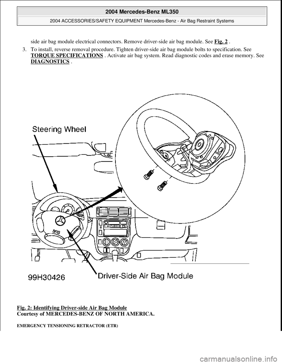
side air bag module electrical connectors. Remove driver-side air bag module. See Fig. 2.
3. To install, reverse removal proc edure. Tighten driver-side air bag module bolts to specification. See
TORQUE SPECIFICATIONS
. Activate air bag system. Read di agnostic codes and erase memory. See
DIAGNOSTICS
.
Fig. 2: Identifying Driver
-side Air Bag Module
Courtesy of MERCEDES-BENZ OF NORTH AMERICA.
EMERGENCY TENSIONING RETRACTOR (ETR)
2004 Mercedes-Benz ML350
2004 ACCESSORIES/SAFETY EQUIPMENT Mercedes-Benz - Air Bag Restraint Systems
me
Saturday, October 02, 2010 3:40:40 PMPage 6 © 2006 Mitchell Repair Information Company, LLC.
Page 792 of 4133
Removal & Installation (Front)
1. Before proceeding, see AIR BAG SAFETY PRECAUTIONS . Disable air bag system. See
DISABLING & ACTIVATI NG AIR BAG SYSTEM
.
2. Move appropriate front seat full y forward. Remove lower trim panel from outer edge of seat cushion
frame. Remove bolt from seat belt end fitting. Remove end fitting from seat cushion. Remove B-pillar
trim panel. Remove bolt from be lt height adjuster. Disconnect ET R electrical connector. Remove ETR
bolts. Remove ETR.
3. To install, reverse removal procedur e. Tighten ETR, seat belt end fitting and belt height adjuster bolts to
specification. See TORQUE SPECIFICATIONS
. Activate air bag system . Read diagnostic codes and
erase memory. See DIAGNOSTICS
.
Removal & Installation (Outer Rear)
1. Before proceeding, see AIR BAG SAFETY PRECAUTIONS . Disable air bag system. See
DISABLING & ACTIVATI NG AIR BAG SYSTEM
.
2. Remove appropriate C-pillar trim panel. Remove bolt from upper seat belt guide bracket. Disconnect
ETR connector. Remove bolts from ETR. Remove ETR.
3. To install, reverse removal proc edure. Tighten ETR bolts and upper seat belt guide bracket bolt to
specification. See TORQUE SPECIFICATIONS
. Activate air bag system Read diagnostic codes and
erase memory. See DIAGNOSTICS
.
HEAD IMPACT AIR BAG MODULE (OUTER REAR)
Removal & Installation
1. Before proceeding, see AIR BAG SAFETY PRECAUTIONS . Disable air bag system. See
DISABLING & ACTIVATI NG AIR BAG SYSTEM
.
2. Remove headliner. See HEADLINER
. Disconnect appropriate head im pact air bag module electrical
connector. Remove screws from rear bracket. Rem ove screws from front and center brackets. Using
Wedge (115-589-03-59-00), remove head impact air ba g module from bracket. Remove head impact air
bag module.
3. To install, reverse removal proce dure. Activate air bag system. Read diagnostic codes and erase memory.
See DIAGNOSTICS
.
HEADLINER
Removal & Installation
1. Before proceeding, see AIR BAG SAFETY PRECAUTIONS . Remove edge trim from sliding/pop-up
roof. Remove front door seals from A- and B-pillars.
2. Remove A-pillar trim panels. Remove front fold ing handle. Remove sun visors and mounting clips.
Remove upper B-pillar trim panels . Remove cargo net holding point c overs. Remove load compartment
handles.
3. Remove coat hooks. Remove C-pill ar trim panels. Remove upper screws from D-pillar trim panels.
Detach rear headliner at roof. Lower headliner until it is supported on front seats. Lower front seat backs
rearward until sufficient ac cess to head impact air ba
g modules is available.
2004 Mercedes-Benz ML350
2004 ACCESSORIES/SAFETY EQUIPMENT Merce des-Benz - Air Bag Restraint Systems
me
Saturday, October 02, 2010 3:40:40 PMPage 7 © 2006 Mitchell Repair Information Company, LLC.