1997 MERCEDES-BENZ ML430 EVap system
[x] Cancel search: EVap systemPage 3050 of 4133
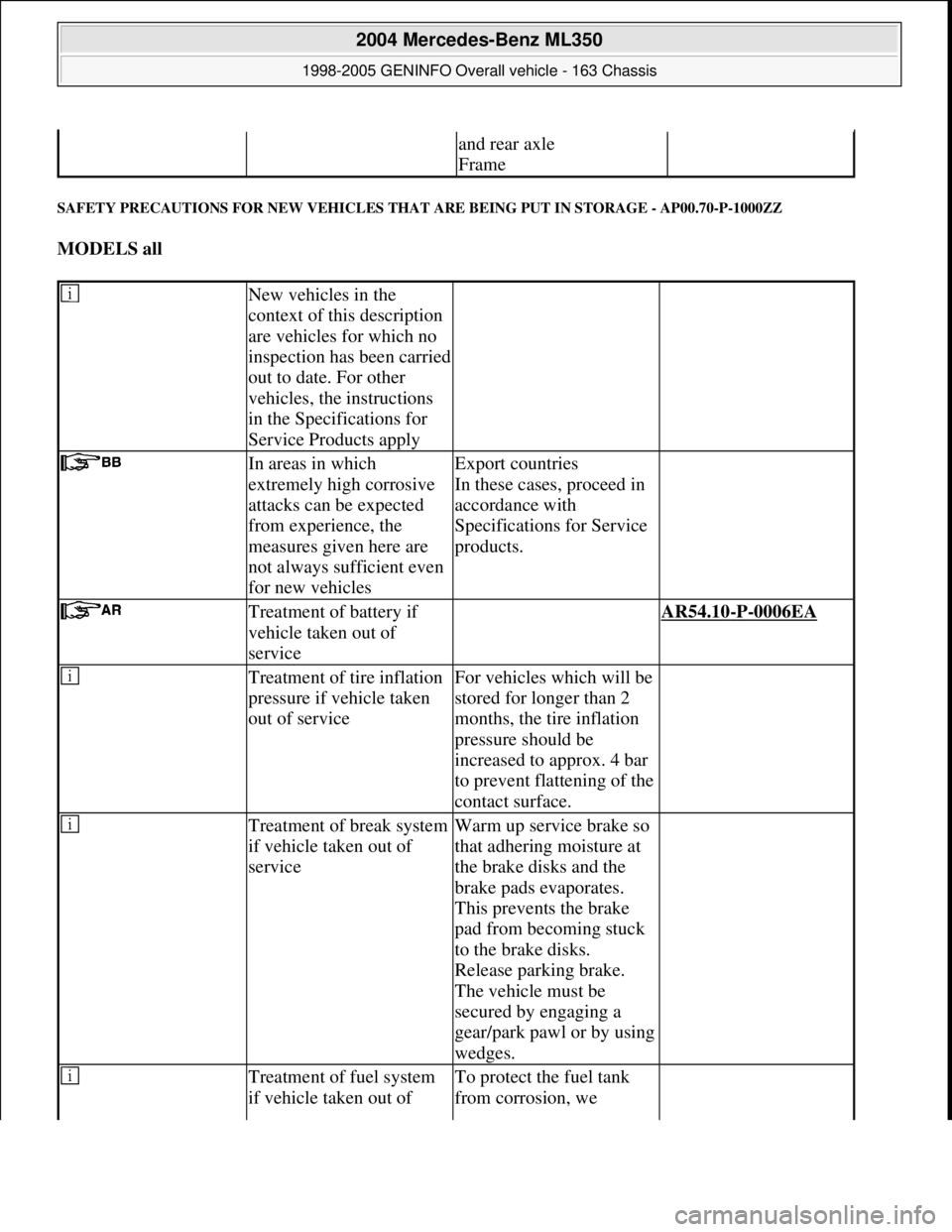
SAFETY PRECAUTIONS FOR NEW VEHICLES THAT ARE BEING PUT IN STORAGE - AP00.70-P-1000ZZ
MODELS all
and rear axle
Frame
New vehicles in the
context of this description
are vehicles for which no
inspection has been carried
out to date. For other
vehicles, the instructions
in the Specifications for
Service Products apply
In areas in which
extremely high corrosive
attacks can be expected
from experience, the
measures given here are
not always sufficient even
for new vehiclesExport countries
In these cases, proceed in
accordance with
Specifications for Service
products.
Treatment of battery if
vehicle taken out of
service AR54.10-P-0006EA
Treatment of tire inflation
pressure if vehicle taken
out of serviceFor vehicles which will be
stored for longer than 2
months, the tire inflation
pressure should be
increased to approx. 4 bar
to prevent flattening of the
contact surface.
Treatment of break system
if vehicle taken out of
serviceWarm up service brake so
that adhering moisture at
the brake disks and the
brake pads evaporates.
This prevents the brake
pad from becoming stuck
to the brake disks.
Release parking brake.
The vehicle must be
secured by engaging a
gear/park pawl or by using
wedges.
Treatment of fuel system
if vehicle taken out of To protect the fuel tank
from corrosion, we
2004 Mercedes-Benz ML350
1998-2005 GENINFO Overall vehicle - 163 Chassis
me
Saturday, October 02, 2010 3:47:52 PMPage 405 © 2006 Mitchell Repair Information Company, LLC.
Page 3216 of 4133
Fig. 2: Locating Climate Control Components
Courtesy of MERCEDES-BENZ OF NORTH AMERICA
FRESH/RECIRCULATION SWITCH
Fresh/recirculation switch controls voltage signal to fresh air recirculation door motor. See Fig. 1 and Fig. 2 .
With switch indicator light on, air will recirculate. With switch indicator light off, air will enter from outside of
vehicle.
A/C CONTROL MODULE
The A/C control module (A/C amplifier) is the control unit for the A/C system. See Fig. 2 . The module
receives inputs from various sensors and processes the information to control various outputs for the A/C
system for optimal control.
The A/C control module inputs are as follows:
A/C Switch
In-Vehicle Air Temperature Sensor
Temperature Selector Knob
Blower Motor Knob
Evaporator Temperature Sensor
Air Mix Damper Door Position Sensor
The A/C control module output functions are as follows:
Air Mix Damper Door Motor
All Activity Module
Fresh/Recirculation Door Motor
ALL ACTIVITY MODULE
All Activity Module (AAM) receives inputs to determine if specified conditions have been met to allow
operation of A/C-heater system. If conditions are met, the AAM will send signals to the A/C compressor,
condenser fans relay and the blower motor relay to command or enable operation.
IN-VEHICLE TEMPERATURE SENSOR
The in-vehicle temperature sensor is a negative temperature coefficient resistor. Sensor sends signals to the A/C
control module to maintain in-vehicle temperature. Sensor is located on the center panel of the instrument
cluster.
DUST FILTER
A dust filter provides filtering of air entering or recirculating in the passenger's compartment. The dust filter is
mounted between blower motor and evaporator, below passen
ger's side of instrument panel, to left of blower
2001 Mercedes-Benz ML320
2000-01 MANUAL A/C-HEATER SYSTEMS ML 320, ML 430 & ML 55
me
Saturday, October 02, 2010 3:25:10 PMPage 5 © 2006 Mitchell Repair Information Company, LLC.
Page 3226 of 4133
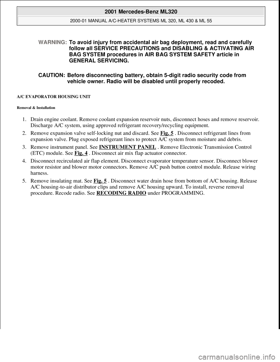
A/C EVAPORATOR HOUSING UNIT
Removal & Installation
1. Drain engine coolant. Remove coolant expansion reservoir nuts, disconnect hoses and remove reservoir.
Discharge A/C system, using approved refrigerant recovery/recycling equipment.
2. Remove expansion valve self-locking nut and discard. See Fig. 5
. Disconnect refrigerant lines from
expansion valve. Plug exposed refrigerant lines to protect A/C system from moisture and debris.
3. Remove instrument panel. See INSTRUMENT PANEL
. Remove Electronic Transmission Control
(ETC) module. See Fig. 4
. Disconnect air mix flap actuator connector.
4. Disconnect recirculated air flap element. Disconnect evaporator temperature sensor. Disconnect blower
motor resistor and blower motor connectors. Remove A/C push button control module. Release wiring
harness.
5. Remove insulating mat. See Fig. 5
. Disconnect water drain hose from bottom of A/C housing. Release
A/C housing-to-air distributor clips and remove A/C housing upward. To install, reverse removal
procedure. Recode radio. See RECODING RADIO
under PROGRAMMING. WARNING:To avoid injury from accidental air bag deployment, read and carefully
follow all SERVICE PRECAUTIONS and DISABLING & ACTIVATING AIR
BAG SYSTEM procedures in AIR BAG SYSTEM SAFETY article in
GENERAL SERVICING.
CAUTION: Before disconnecting battery, obtain 5-digit radio security code from
vehicle owner. Radio will be disabled until properly recoded.
2001 Mercedes-Benz ML320
2000-01 MANUAL A/C-HEATER SYSTEMS ML 320, ML 430 & ML 55
me
Saturday, October 02, 2010 3:25:10 PMPage 15 © 2006 Mitchell Repair Information Company, LLC.
Page 3227 of 4133
Fig. 4: Removing Evaporator Housing Unit
Courtesy of MERCEDES-BENZ OF NORTH AMERICA.
A/C MIX FLAP ACTUATOR
Removal & Installation
Remove instrument panel. See INSTRUMENT PANEL . Disconnect air mix flap actuator connector. Remove
3 screws and remove air mix flap actuator. To install reverse removal procedure.
A/C PUSH BUTTON CONTROL MODULE
Removal & Installation
Disconnect negative battery cable. Remove A/C push button control panel. See A/C PUSH BUTTON
CONTROL PANEL . Remove 4 A/C push button control module screws and remove control module from
2001 Mercedes-Benz ML320
2000-01 MANUAL A/C-HEATER SYSTEMS ML 320, ML 430 & ML 55
me
Saturday, October 02, 2010 3:25:10 PMPage 16 © 2006 Mitchell Repair Information Company, LLC.
Page 3232 of 4133
Fig. 6: Removing Cooling Fans & Condenser
Courtesy of MERCEDES-BENZ OF NORTH AMERICA.
COOLING FANS
Removal & Installation
Remove headlight units. Remove upper frame crossmember, release hood release control cable and remove
crossmember. See Fig. 6
. Remove 2 cooling fans frame bolts on radiator. Disconnect cooling fan connector.
Release outside temperature sensor wiring harness. Pull up on cooling fan and remove. To install, reverse
removal procedure. Ensure cooling fan bottom guides are properly seated in lower mounts.
EVAPORATOR
Removal & Installation
Remove A/C housing unit. See A/C HOUSING UNIT . Remove expansion valve. See Fig. 5 . Discard "O"
rings. Disassemble A/C housing unit. Remove evaporator. Remove evaporator temperature sensor. To install,
reverse removal procedure. Use NEW "O" rings lubricated with refrigerant oil. If installing a new or repair
evaporator, add 1.35 ounces of NEW refrigerant oil to evaporator.
EXPANSION VALVE
Removal & Installation
1. Discharge A/C system, using approved refrigerant recovery/recycling equipment. Without disconnecting
coolant hoses, remove coolant expansion reservoir and set aside. Remove refrigerant line bracket and
loosen clamps. See Fig. 5
. Pull refrigerant lines out of expansion valve.
2. Remove expansion valve self-locking nut and discard. Remove expansion valve. Discard "O" rings. To
install, reverse removal procedure. Use NEW "O" rings lubricated with refrigerant oil. Tighten NEW self-
locking nut to specification. See TORQUE SPECIFICATIONS
.
INSTRUMENT PANEL & INSTRUMENT PANEL CARRIER
Removal & Installation
1. Secure vehicle against rolling. Set transmission selector to "D" position. Obtain radio security code.
Disconnect negative battery cable. Remove driver-side air bag.
2. Place match marks on steering wheel and steering shaft. Remove steering wheel, upper steering column
covers and combination switch. Remove instrument cluster cover frame. Remove one instrument panel
lower section bolt.
3. Remove screws in footwell from left side of instrument panel bottom section. Remove instrument panel
center section. Remove 4 A/C control panel screws and remove control panel. See Fig. 1
. Release pull
cables and disconnect connectors.
4. Remove screws from center section. Remove glove box. Remove screws in footwell from right side of
instrument panel bottom section. Remove entry courtesy lights. Remove end covers and screws.
5. Release 4 "A" clips between instrument panel bottom section and upper section. See Fig. 7
. Release
parkin
g brake release cable from handle. With assistance, remove instrument panel bottom section.
2001 Mercedes-Benz ML320
2000-01 MANUAL A/C-HEATER SYSTEMS ML 320, ML 430 & ML 55
me
Saturday, October 02, 2010 3:25:10 PMPage 21 © 2006 Mitchell Repair Information Company, LLC.
Page 3251 of 4133
Fig. 2: Identifying Ventilation Function - Air Distribution Duct
Function
The ventilation system ensures:
that the windshield and windows are kept without mist.
that there is a supply of fresh air to the vehicle occupants.
that constant and pleasant temperatures are quickly achieved in the vehicle interior.
Ventilation is achieved with the assistance of the blower motor during normal operation, when vehicle is
stationary or to increase the air quantity.
Fresh air is drawn into the evaporator housing via the air inlet. Depending on the automatic air conditioning
push-button control module setting, the air is directed through the air ducts to the air vents in the interior.
The air flows out of the vehicle again through the rear vent via ventilation slots to the left and right in the area
below the rear side windows.
In recirculation mode, air is drawn out from the vehicle interior via the fresh air/recirculation flap (recirculation
setting) by the blower motor and passed to the evaporator housing.
The ventilation is essentially divided into heating operation and cooling operation.
Heating operation
2001 Mercedes-Benz ML320
1998-2005 HVAC Climate Control - 163 Chassis
me
Saturday, October 02, 2010 3:23:14 PMPage 7 © 2006 Mitchell Repair Information Company, LLC.
Page 3268 of 4133
Function
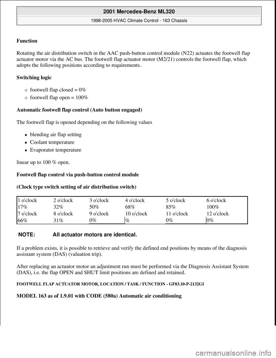
Rotating the air distribution switch in the AAC push-button control module (N22) actuates the footwell flap
actuator motor via the AC bus. The footwell flap actuator motor (M2/21) controls the footwell flap, which
adopts the following positions according to requirements.
Switching logic
footwell flap closed = 0%
footwell flap open = 100%
Automatic footwell flap control (Auto button engaged)
The footwell flap is opened depending on the following values
blending air flap setting
Coolant temperature
Evaporator temperature
linear up to 100 % open.
Footwell flap control via push-button control module
(Clock type switch setting of air distribution switch)
If a problem exists, it is possible to retrieve and verify the defined end positions by means of the diagnosis
assistant system (DAS) (valuation trip).
After replacing an actuator motor an adjustment run must be performed via the Diagnosis Assistant System
(DAS), i.e. the flap OPEN and SHUT limit positions are defined and retained.
FOOTWELL FLAP ACTUATOR MOTOR, LOCATION / TASK / FUNCTION - GF83.10-P-2132GI
MODEL 163 as of 1.9.01 with CODE (580a) Automatic air conditioning
1 o'clock 2 o'clock 3 o'clock 4 o'clock 5 o'clock6 o'clock
17% 32% 50% 68% 85%
100%
7 o'clock 8 o'clock 9 o'clock 10 o'clock 11 o'clock
12 o'clock
66% 31%
0%
%0%0%
NOTE: All actuator motors are identical.
2001 Mercedes-Benz ML320
1998-2005 HVAC Climate Control - 163 Chassis
me
Saturday, October 02, 2010 3:23:15 PMPage 24 © 2006 Mitchell Repair Information Company, LLC.
Page 3280 of 4133
Function
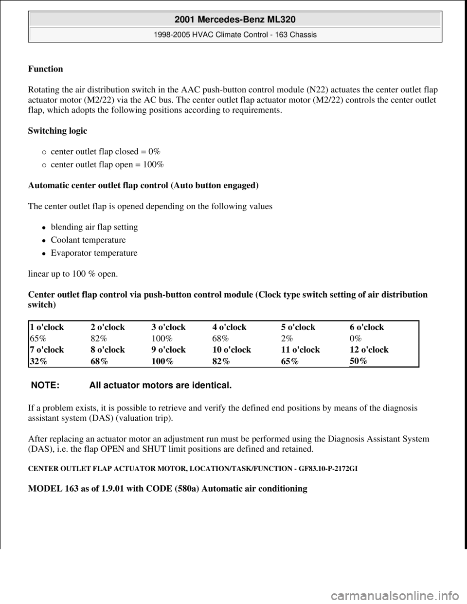
Rotating the air distribution switch in the AAC push-
button control module (N22) actuates the center outlet flap
actuator motor (M2/22) via the AC bus. The center outlet flap actuator motor (M2/22) controls the center outlet
flap, which adopts the following positions according to requirements.
Switching logic
center outlet flap closed = 0%
center outlet flap open = 100%
Automatic center outlet flap control (Auto button engaged)
The center outlet flap is opened depending on the following values
blending air flap setting
Coolant temperature
Evaporator temperature
linear up to 100 % open.
Center outlet flap control via push-button control module (Clock type switch setting of air distribution
switch)
If a problem exists, it is possible to retrieve and verify the defined end positions by means of the diagnosis
assistant system (DAS) (valuation trip).
After replacing an actuator motor an adjustment run must be performed using the Diagnosis Assistant System
(DAS), i.e. the flap OPEN and SHUT limit positions are defined and retained.
CENTER OUTLET FLAP ACTUATOR MOTOR, LOCATION/TASK/FUNCTION - GF83.10-P-2172GI
MODEL 163 as of 1.9.01 with CODE (580a) Automatic air conditioning
1 o'clock 2 o'clock 3 o'clock 4 o'clock 5 o'clock6 o'clock
65% 82% 100% 68% 2%
0%
7 o'clock 8 o'clock 9 o'clock 10 o'clock 11 o'clock
12 o'clock
32% 68% 100% 82% 65%
50%
NOTE: All actuator motors are identical.
2001 Mercedes-Benz ML320
1998-2005 HVAC Climate Control - 163 Chassis
me
Saturday, October 02, 2010 3:23:15 PMPage 36 © 2006 Mitchell Repair Information Company, LLC.