1997 MERCEDES-BENZ ML430 index
[x] Cancel search: indexPage 1718 of 4133
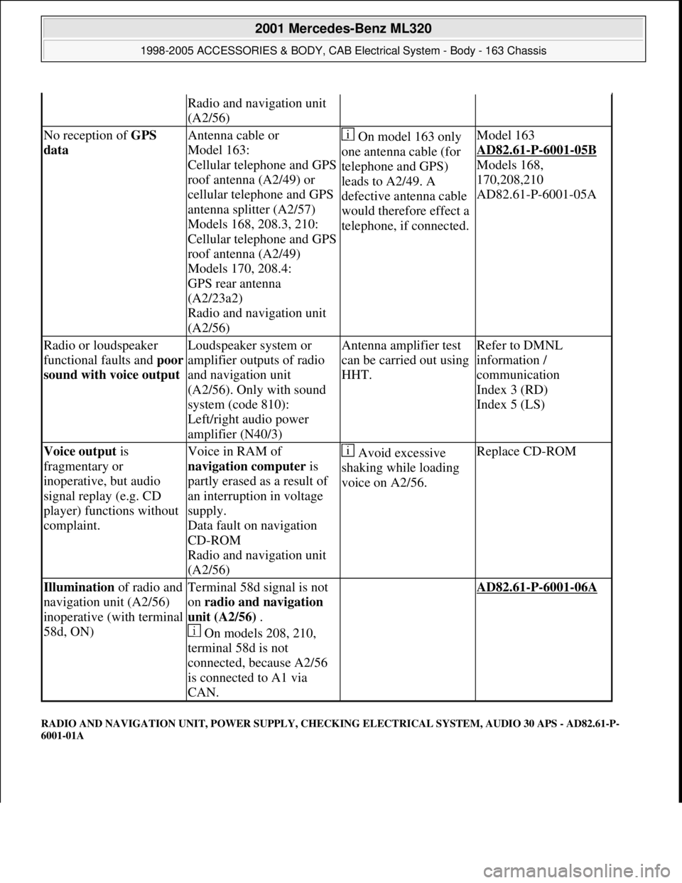
RADIO AND NAVIGATION UNIT, POWER SUPPLY, CHECKING ELECTRICAL SYSTEM, AUDIO 30 APS - AD82.61-P-
6001-01A
Radio and navigation unit
(A2/56)
No reception of GPS
data Antenna cable or
Model 163:
Cellular telephone and GPS
roof antenna (A2/49) or
cellular telephone and GPS
antenna splitter (A2/57)
Models 168, 208.3, 210:
Cellular telephone and GPS
roof antenna (A2/49)
Models 170, 208.4:
GPS rear antenna
(A2/23a2)
Radio and navigation unit
(A2/56) On model 163 only
one antenna cable (for
telephone and GPS)
leads to A2/49. A
defective antenna cable
would therefore effect a
telephone, if connected.Model 163
AD82.61
-P-6001-05B
Models 168,
170,208,210
AD82.61-P-6001-05A
Radio or loudspeaker
functional faults and poor
sound with voice output Loudspeaker system or
amplifier outputs of radio
and navigation unit
(A2/56). Only with sound
system (code 810):
Left/right audio power
amplifier (N40/3)Antenna amplifier test
can be carried out using
HHT.Refer to DMNL
information /
communication
Index 3 (RD)
Index 5 (LS)
Voice output is
fragmentary or
inoperative, but audio
signal replay (e.g. CD
player) functions without
complaint.Voice in RAM of
navigation computer is
partly erased as a result of
an interruption in voltage
supply.
Data fault on navigation
CD-ROM
Radio and navigation unit
(A2/56) Avoid excessive
shaking while loading
voice on A2/56.Replace CD-ROM
Illumination of radio and
navigation unit (A2/56)
inoperative (with terminal
58d, ON)Terminal 58d signal is not
on radio and navigation
unit (A2/56) .
On models 208, 210,
terminal 58d is not
connected, because A2/56
is connected to A1 via
CAN. AD82.61-P-6001-06A
2001 Mercedes-Benz ML320
1998-2005 ACCESSORIES & BODY, CAB Electrical System - Body - 163 Chassis
me
Saturday, October 02, 2010 3:30:08 PMPage 223 © 2006 Mitchell Repair Information Company, LLC.
Page 2089 of 4133

29
Slacken cylinder head bolts (21) in stages,
unscrew
Loosen cylinder head bolts according to
loosening schematic only after engine has
cooled down to prevent cylinder head from
distorting.
AR01.30-P-5800-09B
Installation:
Observe tightening pattern
and tightening instructions of cylinder head
bolts.
Oil thread and head contact surface of
cylinder head bolts.
AR01.30-P-5800-07B
Screwdriver insert
*000589031000
Screwdriver insert
*000589041000
*BA01.30-P-1001-01D
30
Remove cylinder head
Installation:
On Engine 112/113 observe
porous points in the left and right cylinder
head. If porous points are present, sealant
must be applied to the cylinder head gasket.
Notes on application of sealant to cylinder
head gasket.
Engine 112, 113
AH01.30-P-1000-04VA
The sealant must be applied within
10 minutes.
Loctite 5900 sealant.
*BR00.45-Z-1015-01A
31
Inspect version of cylinder head gasket
Assignment of cylinder head gasket
Information for assigning the cylinder head
gaskets
Engine 112, 113
AH01.30-P-1000-06V
32
Check cylinder head bolts (21)
AR01.30-P-5800-03B
*BE01.30-P-1001-04B
33
Clean sealing surfaces, inspect for cracks,
shrink holes and flatness, clean threaded
holes.
Pay attention to dowel sleeves (26) for
locating the cylinder head.
Sealing surfaces of crankcase and
cylinder head are provided with an 0.8 mm
thick silicone layer during series production.
At the time of repair installation, silicone
sealant is applied to the sealing area only in
case of any shrink holes.
The sealant must be applied within
10 minutes.
Loctite 5900 sealant.
*BR00.45-Z-1015-01A
34
Install in the reverse order
Danger!
Risk of accident
caused by vehicle starting
off by itself when engine is running.
Risk of
injury
caused by contusions and burns when
working in engine during starting procedure
Secure vehicle to prevent it from moving.
Wear closed and snug-fitting work clothes.
Do not grasp hot or rotating parts.
AS00.00-Z-0005-01A
35
Run engine and inspect for leaks
36
Inspect cooling system for leaks
Warm up engine to operating temperature
and then inspect cooling system or leaks.
AR20.00-P-1010HA
37
Read out and erase fault memory
Stored faults which can result from cables
being disconnected or from simulation during
removal and installation or test work, have to
be processed and erased in the fault
memories after completing the work:
#
Diagnosis Manual Volume 2 Index 0:
Connecting and using test equipment.
Cylinder head/cylinder head bolts
Number
Designation
Engine
112.910/911/912/
913/914/915/
916/917/920/
921/922/923/
940/941/942/
943/944/945/
946/947/949/
951/953/954/
955/960/961/
970/972/973/975
Engine
113.940/941/
942/943/944/
945/946/948/
960/961/962/
963/965/966/
967/968/969/
980/981/982/
984/986/987/
988/990/991/
992/993
BE01.30-P-1001-04B
Cylinder head bolt
Thread diameter
M
1111
Length (L) when new
mm
141.5141.5
Length (L)
mm
T
144.5
T
144.5
Copyright DaimlerChrysler AG 20.05.2006 CD-Ausgabe G/10/04 . This WIS print-out will not be recorde
d by Modification services.
Page 5
Page 2097 of 4133

29
Slacken cylinder head bolts (21) in stages,
unscrew
Loosen cylinder head bolts according to
loosening schematic only after engine has
cooled down to prevent cylinder head from
distorting.
AR01.30-P-5800-09B
Installation:
Observe tightening pattern
and tightening instructions of cylinder head
bolts.
Oil thread and head contact surface of
cylinder head bolts.
AR01.30-P-5800-07B
Screwdriver insert
*000589031000
Screwdriver insert
*000589041000
*BA01.30-P-1001-01D
30
Remove cylinder head
Installation:
On Engine 112/113 observe
porous points in the left and right cylinder
head. If porous points are present, sealant
must be applied to the cylinder head gasket.
Notes on application of sealant to cylinder
head gasket.
Engine 112, 113
AH01.30-P-1000-04VA
The sealant must be applied within
10 minutes.
Loctite 5900 sealant.
*BR00.45-Z-1015-01A
31
Inspect version of cylinder head gasket
Assignment of cylinder head gasket
Information for assigning the cylinder head
gaskets
Engine 112, 113
AH01.30-P-1000-06V
32
Check cylinder head bolts (21)
AR01.30-P-5800-03B
*BE01.30-P-1001-04B
33
Clean sealing surfaces, inspect for cracks,
shrink holes and flatness, clean threaded
holes.
Pay attention to dowel sleeves (26) for
locating the cylinder head.
Sealing surfaces of crankcase and
cylinder head are provided with an 0.8 mm
thick silicone layer during series production.
At the time of repair installation, silicone
sealant is applied to the sealing area only in
case of any shrink holes.
The sealant must be applied within
10 minutes.
Loctite 5900 sealant.
*BR00.45-Z-1015-01A
34
Install in the reverse order
Danger!
Risk of accident
caused by vehicle starting
off by itself when engine is running.
Risk of
injury
caused by contusions and burns when
working in engine during starting procedure
Secure vehicle to prevent it from moving.
Wear closed and snug-fitting work clothes.
Do not grasp hot or rotating parts.
AS00.00-Z-0005-01A
35
Run engine and inspect for leaks
36
Inspect cooling system for leaks
Warm up engine to operating temperature
and then inspect cooling system or leaks.
AR20.00-P-1010HA
37
Read out and erase fault memory
Stored faults which can result from cables
being disconnected or from simulation during
removal and installation or test work, have to
be processed and erased in the fault
memories after completing the work:
#
Diagnosis Manual Volume 2 Index 0:
Connecting and using test equipment.
Cylinder head/cylinder head bolts
Number
Designation
Engine
112.910/911/912/
913/914/915/
916/917/920/
921/922/923/
940/941/942/
943/944/945/
946/947/949/
951/953/954/
955/960/961/
970/972/973/975
Engine
113.940/941/
942/943/944/
945/946/948/
960/961/962/
963/965/966/
967/968/969/
980/981/982/
984/986/987/
988/990/991/
992/993
BE01.30-P-1001-04B
Cylinder head bolt
Thread diameter
M
1111
Length (L) when new
mm
141.5141.5
Length (L)
mm
T
144.5
T
144.5
Copyright DaimlerChrysler AG 20.05.2006 CD-Ausgabe G/10/04 . This WIS print-out will not be recorde
d by Modification services.
Page 5
Page 2203 of 4133
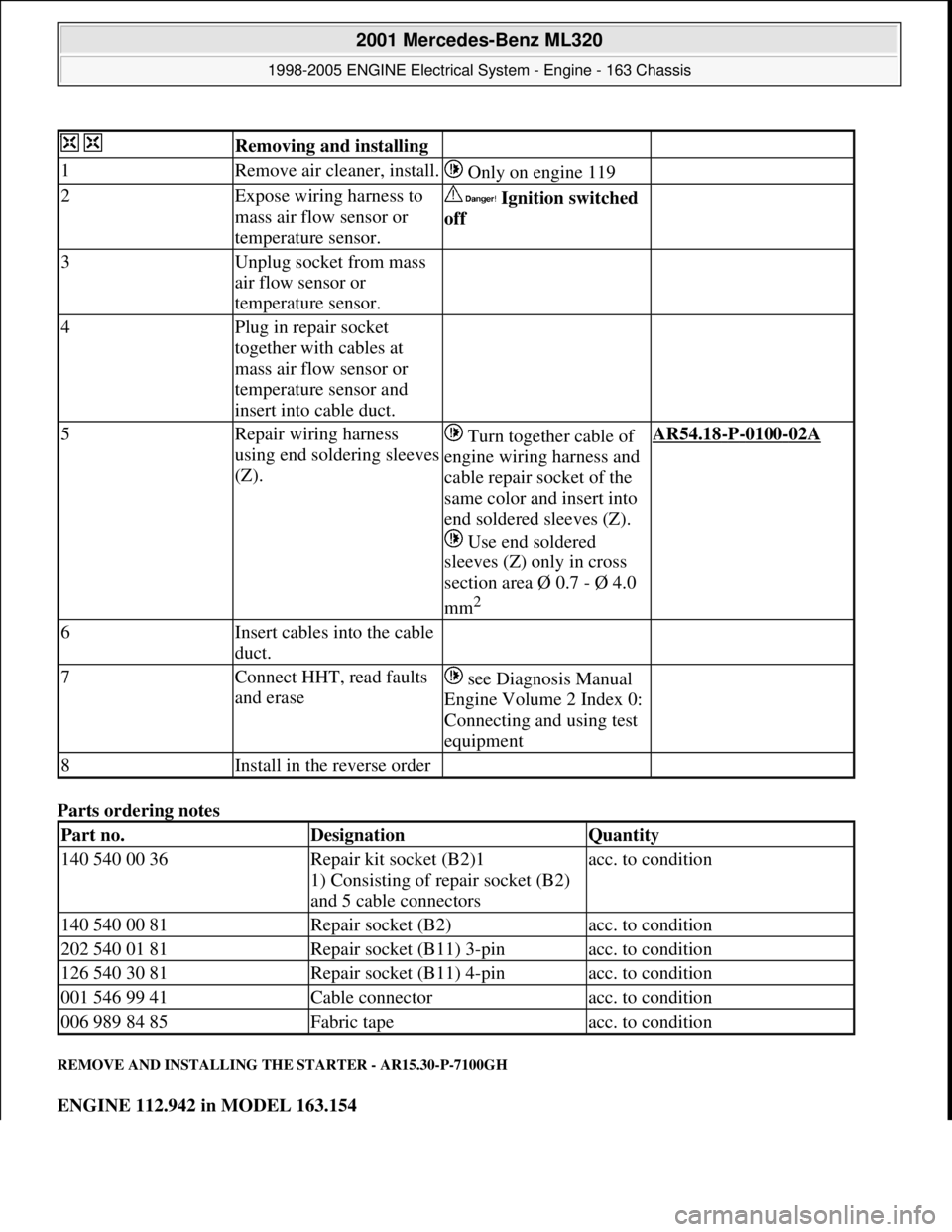
Parts ordering notes
REMOVE AND INSTALLING THE STARTER - AR15.30-P-7100GH
ENGINE 112.942 in MODEL 163.154
Removing and installing
1Remove air cleaner, install. Only on engine 119
2Expose wiring harness to
mass air flow sensor or
temperature sensor. Ignition switched
off
3Unplug socket from mass
air flow sensor or
temperature sensor.
4Plug in repair socket
together with cables at
mass air flow sensor or
temperature sensor and
insert into cable duct.
5Repair wiring harness
using end soldering sleeves
(Z). Turn together cable of
engine wiring harness and
cable repair socket of the
same color and insert into
end soldered sleeves (Z).
Use end soldered
sleeves (Z) only in cross
section area Ø 0.7 - Ø 4.0
mm
2
AR54.18-P-0100-02A
6Insert cables into the cable
duct.
7Connect HHT, read faults
and erase see Diagnosis Manual
Engine Volume 2 Index 0:
Connecting and using test
equipment
8Install in the reverse order
Part no.DesignationQuantity
140 540 00 36Repair kit socket (B2)1
1) Consisting of repair socket (B2)
and 5 cable connectorsacc. to condition
140 540 00 81Repair socket (B2)acc. to condition
202 540 01 81Repair socket (B11) 3-pinacc. to condition
126 540 30 81Repair socket (B11) 4-pinacc. to condition
001 546 99 41Cable connectoracc. to condition
006 989 84 85Fabric tapeacc. to condition
2001 Mercedes-Benz ML320
1998-2005 ENGINE Electrical System - Engine - 163 Chassis
me
Saturday, October 02, 2010 3:18:54 PMPage 49 © 2006 Mitchell Repair Information Company, LLC.
Page 2401 of 4133
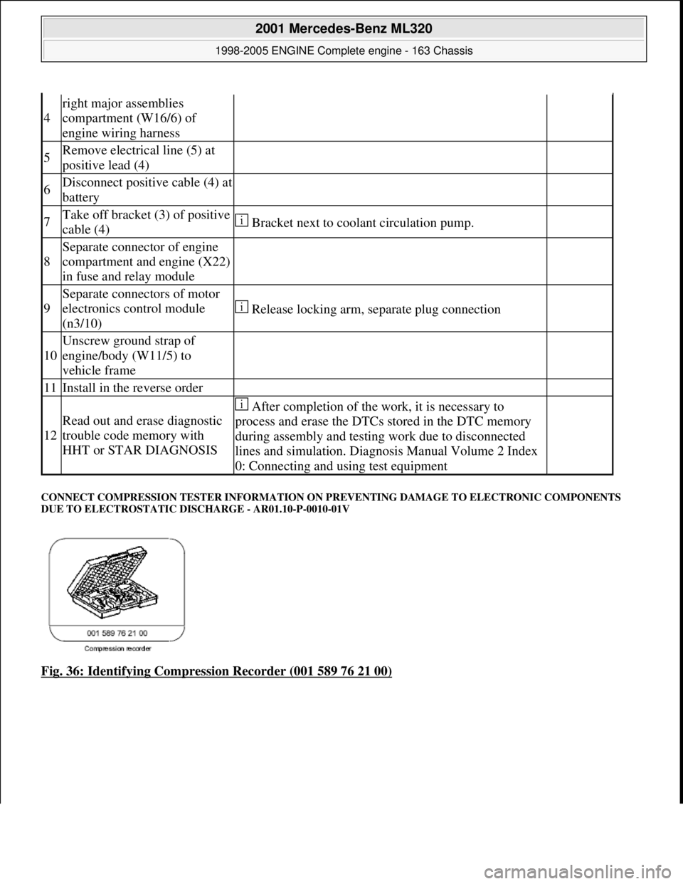
CONNECT COMPRESSION TESTER INFORMATION ON PR EVENTING DAMAGE TO ELECTRONIC COMPONENTS
DUE TO ELECTROSTATIC DI SCHARGE - AR01.10-P-0010-01V
Fig. 36: Identifying Compression Recorder (001 589 76 21 00)
4
right major assemblies
compartment (W16/6) of
engine wiring harness
5Remove electrical line (5) at
positive lead (4)
6Disconnect positive cable (4) at
battery
7Take off bracket (3) of positive
cable (4) Bracket next to coolant circulation pump.
8
Separate connector of engine
compartment and engine (X22)
in fuse and relay module
9
Separate connectors of motor
electronics control module
(n3/10)
Release locking arm, separate plug connection
10
Unscrew ground strap of
engine/body (W11/5) to
vehicle frame
11Install in the reverse order
12
Read out and erase diagnostic
trouble code memory with
HHT or STAR DIAGNOSIS
After completion of the work, it is necessary to
process and erase the DTCs stored in the DTC memory
during assembly and testing work due to disconnected
lines and simulation. Diagnosis Manual Volume 2 Index
0: Connecting and using test equipment
2001 Mercedes-Benz ML320
1998-2005 ENGINE Complete engine - 163 Chassis
me
Saturday, October 02, 2010 3:17:56 PMPage 45 © 2006 Mitchell Repair Information Company, LLC.
Page 2414 of 4133
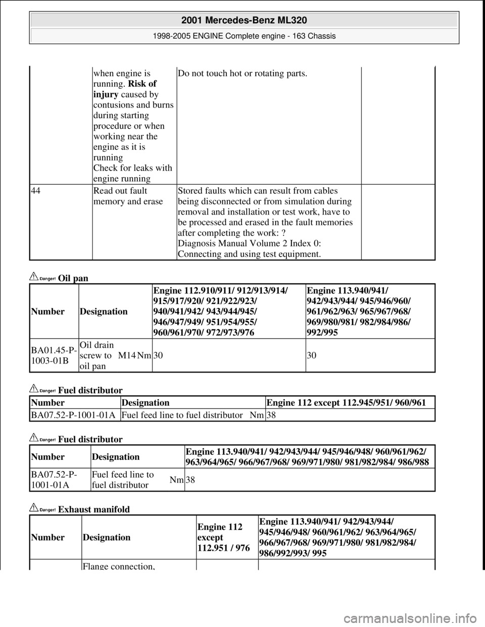
Oil pan
Fuel distributor
Fuel distributor
Exhaust manifold
when engine is
running. Risk of
injury caused by
contusions and burns
during starting
procedure or when
working near the
engine as it is
running
Check for leaks with
engine runningDo not touch hot or rotating parts.
44Read out fault
memory and eraseStored faults which can result from cables
being disconnected or from simulation during
removal and installation or test work, have to
be processed and erased in the fault memories
after completing the work: ?
Diagnosis Manual Volume 2 Index 0:
Connecting and using test equipment.
NumberDesignation
Engine 112.910/911/ 912/913/914/
915/917/920/ 921/922/923/
940/941/942/ 943/944/945/
946/947/949/ 951/954/955/
960/961/970/ 972/973/976Engine 113.940/941/
942/943/944/ 945/946/960/
961/962/963/ 965/967/968/
969/980/981/ 982/984/986/
992/995
BA01.45-P-
1003-01BOil drain
screw to
oil pan
M14Nm3030
NumberDesignationEngine 112 except 112.945/951/ 960/961
BA07.52-P-1001-01AFuel feed line to fuel distributorNm38
NumberDesignationEngine 113.940/941/ 942/943/944/ 945/946/948/ 960/961/962/
963/964/965/ 966/967/968/ 969/971/ 980/ 981/982/984/ 986/988
BA07.52-P-
1001-01AFuel feed line to
fuel distributorNm38
NumberDesignation
Engine 112
except
112.951 / 976Engine 113.940/941/ 942/943/944/
945/946/948/ 960/961/962/ 963/964/965/
966/967/968/ 969/971/980/ 981/982/984/
986/992/993/ 995
Flange connection,
2001 Mercedes-Benz ML320
1998-2005 ENGINE Complete engine - 163 Chassis
me
Saturday, October 02, 2010 3:17:56 PMPage 58 © 2006 Mitchell Repair Information Company, LLC.
Page 2446 of 4133
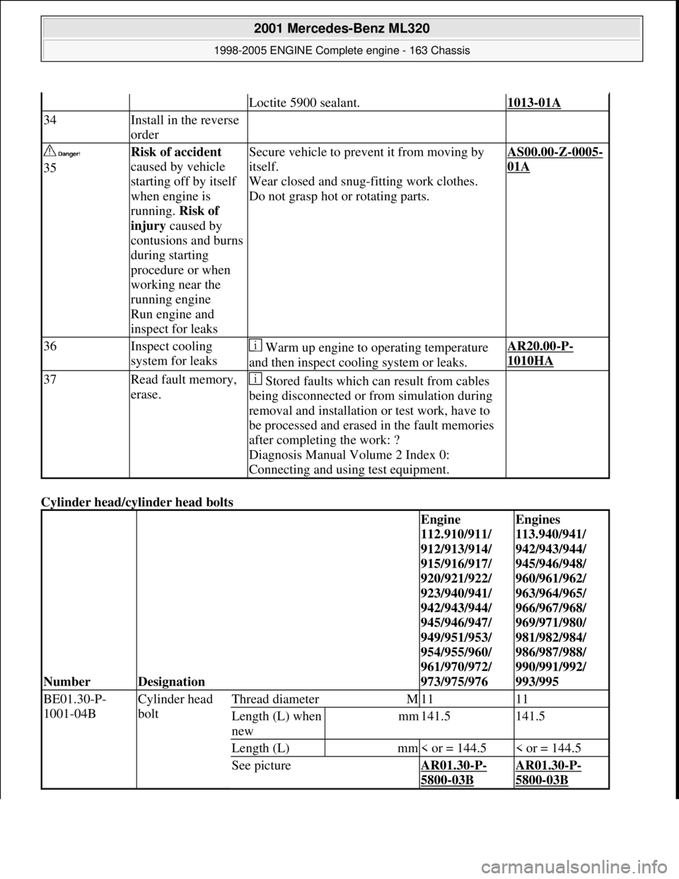
Cylinder head/cyl inder head bolts
Loctite 5900 sealant.1013-01A
34Install in the reverse
order
35Risk of accident
caused by vehicle
starting off by itself
when engine is
running. Risk of
injury caused by
contusions and burns
during starting
procedure or when
working near the
running engine
Run engine and
inspect for leaksSecure vehicle to prev ent it from moving by
itself.
Wear closed and snug-fitting work clothes.
Do not grasp hot or rotating parts.AS00.00-Z-0005-
01A
36Inspect cooling
system for leaks Warm up engine to operating temperature
and then inspect cooling system or leaks.AR20.00-P-
1010HA
37Read fault memory,
erase. Stored faults which can result from cables
being disconnected or from simulation during
removal and installation or test work, have to
be processed and erased in the fault memories
after completing the work: ?
Diagnosis Manual Volume 2 Index 0:
Connecting and using test equipment.
NumberDesignation
Engine
112.910/911/
912/913/914/
915/916/917/
920/921/922/
923/940/941/
942/943/944/
945/946/947/
949/951/953/
954/955/960/
961/970/972/
973/975/976Engines
113.940/941/
942/943/944/
945/946/948/
960/961/962/
963/964/965/
966/967/968/
969/971/980/
981/982/984/
986/987/988/
990/991/992/
993/995
BE01.30-P-
1001-04BCylinder head
boltThread diameterM1111
Length (L) when
newmm141.5141.5
Length (L)mm< or = 144.5< or = 144.5
See pictureAR01.30-P-
5800-03B
AR01.30-P-
5800-03B
2001 Mercedes-Benz ML320
1998-2005 ENGINE Complete engine - 163 Chassis
me
Saturday, October 02, 2010 3:17:57 PMPage 90 © 2006 Mitchell Repair Information Company, LLC.
Page 2462 of 4133
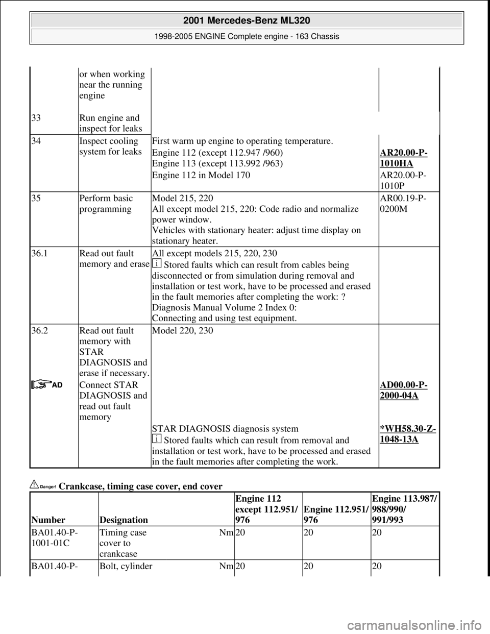
Crankcase, timing case cover, end cover
or when working
near the running
engine
33Run engine and
inspect for leaks
34Inspect cooling
system for leaksFirst warm up engine to operating temperature.
Engine 112 (except 112.947 /960)
Engine 113 (except 113.992 /963)AR20.00-P-
1010HA
Engine 112 in Model 170AR20.00-P-
1010P
35Perform basic
programmingModel 215, 220
All except model 215, 220: Code radio and normalize
power window.
Vehicles with stationary he ater: adjust time display on
stationary heater.AR00.19-P-
0200M
36.1Read out fault
memory and eraseAll except models 215, 220, 230
Stored faults which can result from cables being
disconnected or from simu lation during removal and
installation or test work, have to be processed and erased
in the fault memories after completing the work: ?
Diagnosis Manual Volume 2 Index 0:
Connecting and using test equipment.
36.2Read out fault
memory with
STAR
DIAGNOSIS and
erase if necessary.Model 220, 230
Connect STAR
DIAGNOSIS and
read out fault
memory AD00.00-P-
2000-04A
STAR DIAGNOSIS diagnosis system
Stored faults which can result from removal and
installation or test work, have to be processed and erased
in the fault memories after completing the work.*WH58.30-Z-
1048-13A
NumberDesignation
Engine 112
except 112.951/
976
Engine 112.951/
976
Engine 113.987/
988/990/
991/993
BA01.40-P-
1001-01CTiming case
cover to
crankcaseNm202020
BA01.40-P- Bolt, cylinder Nm202020
2001 Mercedes-Benz ML320
1998-2005 ENGINE Complete engine - 163 Chassis
me
Saturday, October 02, 2010 3:17:57 PMPage 106 © 2006 Mitchell Repair Information Company, LLC.