1997 MERCEDES-BENZ ML430 wheel torque
[x] Cancel search: wheel torquePage 3154 of 4133
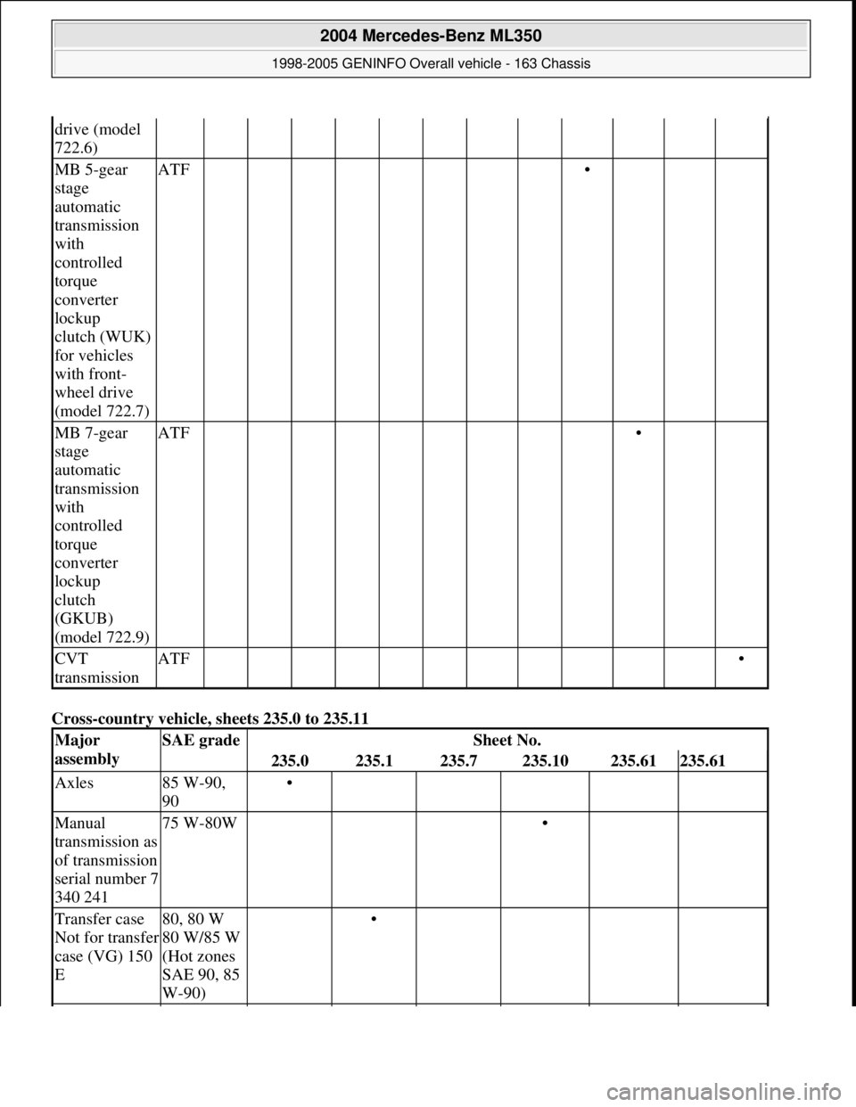
Cross-country vehicle, sheets 235.0 to 235.11
drive (model
722.6)
MB 5-gear
stage
automatic
transmission
with
controlled
torque
converter
lockup
clutch (WUK)
for vehicles
with front-
wheel drive
(model 722.7)ATF •
MB 7-gear
stage
automatic
transmission
with
controlled
torque
converter
lockup
clutch
(GKUB)
(model 722.9)ATF •
CVT
transmissionATF •
Major
assemblySAE gradeSheet No.
235.0235.1235.7235.10235.61235.61
Axles85 W-90,
90•
Manual
transmission as
of transmission
serial number 7
340 24175 W-80W •
Transfer case
Not for transfer
case (VG) 150
E80, 80 W
80 W/85 W
(Hot zones
SAE 90, 85
W-90) •
2004 Mercedes-Benz ML350
1998-2005 GENINFO Overall vehicle - 163 Chassis
me
Saturday, October 02, 2010 3:47:56 PMPage 509 © 2006 Mitchell Repair Information Company, LLC.
Page 3232 of 4133
Fig. 6: Removing Cooling Fans & Condenser
Courtesy of MERCEDES-BENZ OF NORTH AMERICA.
COOLING FANS
Removal & Installation
Remove headlight units. Remove upper frame crossmember, release hood release control cable and remove
crossmember. See Fig. 6
. Remove 2 cooling fans frame bolts on radiator. Disconnect cooling fan connector.
Release outside temperature sensor wiring harness. Pull up on cooling fan and remove. To install, reverse
removal procedure. Ensure cooling fan bottom guides are properly seated in lower mounts.
EVAPORATOR
Removal & Installation
Remove A/C housing unit. See A/C HOUSING UNIT . Remove expansion valve. See Fig. 5 . Discard "O"
rings. Disassemble A/C housing unit. Remove evaporator. Remove evaporator temperature sensor. To install,
reverse removal procedure. Use NEW "O" rings lubricated with refrigerant oil. If installing a new or repair
evaporator, add 1.35 ounces of NEW refrigerant oil to evaporator.
EXPANSION VALVE
Removal & Installation
1. Discharge A/C system, using approved refrigerant recovery/recycling equipment. Without disconnecting
coolant hoses, remove coolant expansion reservoir and set aside. Remove refrigerant line bracket and
loosen clamps. See Fig. 5
. Pull refrigerant lines out of expansion valve.
2. Remove expansion valve self-locking nut and discard. Remove expansion valve. Discard "O" rings. To
install, reverse removal procedure. Use NEW "O" rings lubricated with refrigerant oil. Tighten NEW self-
locking nut to specification. See TORQUE SPECIFICATIONS
.
INSTRUMENT PANEL & INSTRUMENT PANEL CARRIER
Removal & Installation
1. Secure vehicle against rolling. Set transmission selector to "D" position. Obtain radio security code.
Disconnect negative battery cable. Remove driver-side air bag.
2. Place match marks on steering wheel and steering shaft. Remove steering wheel, upper steering column
covers and combination switch. Remove instrument cluster cover frame. Remove one instrument panel
lower section bolt.
3. Remove screws in footwell from left side of instrument panel bottom section. Remove instrument panel
center section. Remove 4 A/C control panel screws and remove control panel. See Fig. 1
. Release pull
cables and disconnect connectors.
4. Remove screws from center section. Remove glove box. Remove screws in footwell from right side of
instrument panel bottom section. Remove entry courtesy lights. Remove end covers and screws.
5. Release 4 "A" clips between instrument panel bottom section and upper section. See Fig. 7
. Release
parkin
g brake release cable from handle. With assistance, remove instrument panel bottom section.
2001 Mercedes-Benz ML320
2000-01 MANUAL A/C-HEATER SYSTEMS ML 320, ML 430 & ML 55
me
Saturday, October 02, 2010 3:25:10 PMPage 21 © 2006 Mitchell Repair Information Company, LLC.
Page 3340 of 4133
AC OFF BUTTON, FUNCTION - GF83.40-P-2107-01GI
Function
When the AC OFF button ( ) on the automatic air conditioning push-button control module is pressed an
LED comes on, the refrigerant compressor is switched off and cooling therefore switched off The air is no
longer cooled and dried.
Vehicles with diesel engine:
Additionally the electric heater booster is switched off. All other functions are retained.
In order to switch off the refrigerant compressor the push-button control module sends a switch-off request over
the CAN. At the same time, the compressor torque value is set to "0". After a specified time delay the
refrigerant compressor is switched off.
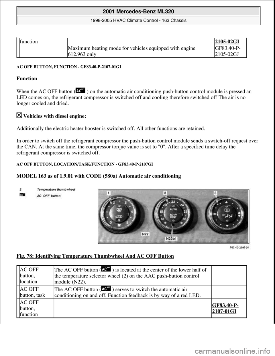
AC OFF BUTTON, LOCATION/TASK/FUNCTION - GF83.40-P-2107GI
MODEL 163 as of 1.9.01 with CODE (580a) Automatic air conditioning
Fig. 78: Identifying Temperature Thumbwheel And AC OFF Button
function2105-02GI
Maximum heating mode for vehicles equipped with engine
612.963 onlyGF83.40-P-
2105-02GJ
AC OFF
button,
locationThe AC OFF button ( ) is located at the center of the lower half of
the temperature selector wheel (2) on the AAC push-button control
module (N22).
AC OFF
button, taskThe AC OFF button ( ) serves to switch the automatic air
conditioning on and off. Function feedback is by way of a red LED.
AC OFF
button,
function
GF83.40-P-
2107-01GI
2001 Mercedes-Benz ML320
1998-2005 HVAC Climate Control - 163 Chassis
me
Saturday, October 02, 2010 3:23:16 PMPage 96 © 2006 Mitchell Repair Information Company, LLC.
Page 3479 of 4133

BT27.00-Z-9999AZ
Technical modifications: Passenger cars: Automatic transmission
30.4.97
MODEL all
Vacuum unit for modulating pressure modified
TRANSMISSION 722.3 /5 as of 15.8.92
BT27.10-P-0001-01A
Secondary pump dispensed with
TRANSMISSION 722.5## ## as of 3652931
BT27.10-P-0002-01A
Control pressure cable with vacuum actuators
standardized
TRANSMISSION 722.3 /4 /5 as of 1.7.93
BT27.10-P-0003-01A
Sump volume modified
TRANSMISSION 722.7## ## as of 0054011
as of 29.7.99
BT27.10-P-0004-01A
Additional shim between deep-groove ball
bearing and output flange
TRANSMISSION 722 ...
BT27.10-P-0005-01A
Oil pan and overflow tube modified
TRANSMISSION 722.901
BT27.10-P-0006-01W
Retaining lug added to electrohydraulic
control module
TRANSMISSION 722.6## # as of 0026195
BT27.19-P-0001-01A
Caps for solenoid valve, new
TRANSMISSION 722.6 as of 1.8.97
BT27.19-P-0003-01A
Oil drain plug on torque converter deleted
TRANSMISSION 722.6## /6## ## as of
1772285 as of 22.9.99
BT27.20-P-0001-01A
Small intermediate plate modified
TRANSMISSION 722.5## ## as of 3987361
as of 15.3.94
BT27.35-P-0001-01A
Installation of a pressure feed valve
TRANSMISSION 722.6## # as of 0027083
BT27.35-P-0002-01A
Primary pump non-return valve dispensed with
TRANSMISSION 722.5## ## as of 3652931
BT27.35-P-0003-01A
Strainer for modulating pressure and shift
pressure control solenoid valve, new
TRANSMISSION 722.6## ## as of 0538312
BT27.35-P-0004-01A
Strainer in inlet to converter lock-up control
solenoid valve, newTRANSMISSION 722.6## ## as of 0485895
BT27.35-P-0005-01A
Feed B1 enlarged
TRANSMISSION 722.5 as of 15.8.91
BT27.40-P-0001-01A
Fluid reservoir deleted
TRANSMISSION 722.7## ## as of 0111673
as of 11.9.00
BT27.40-P-0002-01A
Magnet in oil pan, new part
TRANSMISSION 722.6## ## as of 2871384
as of 17.4.01, 722.7## ## as of 0153700 as
of 9.7.01
BT27.40-P-0003-01A
Piston B1 modified
TRANSMISSION 722.5## ## as of 3746852
as of 15.6.92, 722.3## ## as of 3969172
BT27.50-P-0002-01A
Plain bearing of input shaft changed to an anti-
friction bearing
TRANSMISSION 722 ...
BT27.50-P-0002-02A
One-way valve dispensed with
TRANSMISSION 722.5## ## as of 3652931
BT27.50-P-0007-01A
Outer multiple-disc carrier B1 modified
TRANSMISSION 722.6## # as of 0005900
BT27.50-P-0008-01A
Peak-to-valley height on piston B2 modified
TRANSMISSION 722.6## # as of 0023104
BT27.50-P-0009-01A
Piston B2 changed
TRANSMISSION 722.6## ## as of 0552036
as of 1.8.97
BT27.50-P-0010-01A
Friction bearing in sun wheel of rear planet
gear set converted to anti-friction bearing
TRANSMISSION 722 ...
BT27.50-P-0011-01A
Conversion from 18° to 23° gearing in front
and rear planetary gear system
TRANSMISSION 722 ...
BT27.50-P-0012-01A
Multi-disks for B1, K1 and K3 changed
TRANSMISSION 722.6## ## as of 3947440
as of 2.9.02
BT27.50-P-0013-01A
Thickness of friction and steel disks K3
changed
TRANSMISSION 722.6
BT27.51-P-0001-01A
Thickness of steel plates of B1, K1 and K2
modified
TRANSMISSION 722.6## ## as of 1596205
as of 15.6.99
BT27.51-P-0002-01A
Additional dished washer in multi-plate set K2
TRANSMISSION 722.6## ## as of 1596205
as of 15.6.99
BT27.51-P-0003-01A
Center shift modified
TRANSMISSION 722.6
BT27.60-P-0001-01A
Deletion shift lock cable ignition lock to
transmission
TRANSMISSION 722.7 in MODEL
WDB168.### ## as of 548031 as of 10.1.01
BT27.60-P-0001-02A
Selector lever soldered
TRANSMISSION 722.6 as of 1.5.96
BT27.60-P-0002-01A
Deletion of lever for shift lock cable ignition
lock at transmission
TRANSMISSION 722.700 ## as of 0129631
as of 24.1.01, 722.701 ## as of 0132072 as
of 8.2.01
BT27.60-P-0003-01A
Copyright DaimlerChrysler AG 28.05.2006 CD-Ausgabe G/10/04 . This WIS print-out will not be recorde
d by Modification services.
Page 1
Page 3485 of 4133

Rims
D
When changing wheels, for instance, when replacing steel
wheels with light-alloy rims, ensure that the wheel bolts
required for the spare wheel are stored in a clearly visible
location.
D
Since December 1994 models 202 and 124 with special
equipment light alloy disk wheels, are supplied with a sheet
steel spare wheel instead of a light alloy spare wheel. The
necessary wheel bolts are included with the steel spare wheel.
D
Only use approved Mercedes-Benz rims of the same version.
D
Reinforced steel rims are identified by a sticker on the wheel
disc.
D
The wheel bolts on steel and light-alloy rims should always be
tightened to the specified tightening torque using a torque
wrench.
It is not necessary to retorque the lug bolts after approximately
100 to 500 km.
D
The seat for the tire bead must display no corrosion marks.
D
Before inserting a new rubber valve, clean the contact surfaces
on the disk wheel.
On sheet steel-disk wheel wheel trims must be fitted to support
the rubber valve.
Damaged or deformed rims must not be repaired.
Tire pressure monitor
D
Before replacing a tire, check the date of manufacturer of the
wheel sensor: wheel sensors which are more than 5 years old
must be replaced.
D
Use STAR DIAGNOSIS to read out the actual values of the tire
pressure monitor. Check the remaining life of the wheel sensor
battery, replace the wheel sensor if necessary.
Copyright DaimlerChrysler AG 06.07.2006 CD-Ausgabe G/10/04 . This WIS print-out will not be recorde
d by Modification services.
Page 2
Page 3891 of 4133
Fig. 4: Connecting Hand Held Tester Scan Tool To OBD-II Data Link Connector
Courtesy of MERCEDES-BENZ OF NORTH AMERICA.
TESTING
Starter malfunctions may cause a Di agnostic Trouble Codes (DTCs) to be stored in Motor Electronics
Sequential Fuel Injection (ME-SFI) sy stem. After repairs are completed check for and erase any DTCs stored in
(ME-SFI) system. See appropriate SE LF-DIAGNOSTICS article in ENGINE PERFORMANCE. If cause of
starter malfunction is not engine pe rformance related, replace starter.
REMOVAL & INSTALLATION
STARTER
Removal & Installation
1. Disconnect and shield negative battery cable. See BATTERY DISCONNECT/CONNECT under
SERVICE PRECAUTIONS.
2. Remove nut (2) for inner fender. See Fig. 5
. Pull front and rear section of inner fender (1) downward.
Move inner fender away inward and downward. Pull toward outside over wheel. DO NOT damage fender
cutout or paint.
3. On vehicles with 112 engine, remove nut (6) at shield (5) of left engine mount and take out shield. See
Fig. 6
.
4. On all vehicles, disconnect circuit 30 (1) and circuit 50 (2) cables from starter. See Fig. 6
. Remove bolts
(3) for starter-to-crankcase. Take starter (M1) out to the side.
5. If replacing starter on vehicles with manual transmission, check ring gear at flywheel for wear and
damage. If replacing starter on vehicles with auto matic transmission, check ring gear on drive plate for
wear and damage. Repair or repl ace damaged parts as necessary.
6. To install, reverse removal proce dure. Replace bolts with locking splines, micro-encapsulated bolts and
self-locking nuts. Mating thread of mi cro-encapsulated bolts must be cleaned to remove all residue of old
bolt locking compound. Tighten fasteners to specification. See TORQUE SPECIFICATIONS
. Connect
battery. See BATTERY DISCONNECT/CONNECTunder SERVICE PRECAUTIONS.
NOTE: Numbers and letters in text refe
r to numbers and letters in figures.
2001 Mercedes-Benz ML320
2001-04 STARTING & CHARGING SYSTEMS Starters - 163 Chassis
me
Saturday, October 02, 2010 3:19:47 PMPage 9 © 2006 Mitchell Repair Information Company, LLC.
Page 3935 of 4133
Rear axle shock absorber
Wheel location
REMOVAL & INSTALLATION
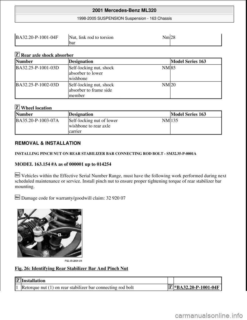
INSTALLING PINCH NUT ON REAR STABILIZER BAR CONNECTING ROD BOLT - SM32.35-P-0001A
MODEL 163.154 #A as of 000001 up to 014254
Vehicles within the Effective Serial Number Range, must have the following work performed during next
scheduled maintenance or service. Install pinch nut to ensure proper tightening torque of rear stabilizer bar
mounting.
Damage code for warranty/goodwill claim: 32 920 07
Fig. 26: Identifying Rear Stabilizer Bar And Pinch Nut
BA32.20-P-1001-04FNut, link rod to torsion
barNm28
NumberDesignationModel Series 163
BA32.25-P-1001-03DSelf-locking nut, shock
absorber to lower
wishboneNM85
BA32.25-P-1002-03DSelf-locking nut, shock
absorber to frame side
memberNM20
NumberDesignationModel Series 163
BA35.20-P-1003-07ASelf-locking nut of lower
wishbone to rear axle
carrierNM135
Installation
1Retorque nut (1) on rear stabilizer bar connecting rod bolt*BA32.20-P-1001-04F
2001 Mercedes-Benz ML320
1998-2005 SUSPENSION Suspension - 163 Chassis
me
Saturday, October 02, 2010 3:37:36 PMPage 27 © 2006 Mitchell Repair Information Company, LLC.
Page 3995 of 4133

BA40.10-P-1001-01A
Wheel bolt
Nm
150150
126 589 04 09 00
Wrench socket
Commercially available tools
(see Workshop Equipment Manual)
Number
Designation
Make (e. g.)
Order number
WH58.30-Z-1002-10A
Electric or compressed air impact wrench with limited tightening torque,
see
D
trial reports on test benches and tools for
Mercedes Benz workshops, Volume 2, 40.1
D
Workshop Equipment Manual Volume 1 "G" Group 40
651004700
6510053001
Copyright DaimlerChrysler AG 06.07.2006 CD-Ausgabe G/10/04 . This WIS print-out will not be recorde
d by Modification services.
Page 2