Page 1093 of 4133
289 Technical data
Spare parts service
Warranty coverage
Identification labels
Layout of poly-V-belt drive
Engine
Rims and tires
Electrical system
Main Dimensions
Weights
Fuels, coolants, lubricants etc.
Consumer information
Page 1100 of 4133
296 Technical dataRims and tiresSpare wheelModel
ML 350, ML 500
Rim
4Jx18 H2 ET0
Wheel offset
0 in (0 mm)
Space-saver tire
T155 / 90 D18 113M
1
1Must not be used with snow chains.
Page 1129 of 4133

325 Index
F
Fastening the seat belts 42
Fine adjustment
Cruise control 152
First aid kit 257
Flat tire 274
Lowering the vehicle 276
Mounting the spare wheel 274
Preparing the vehicle 274
Spare wheel 259
Flexible Service System (FSS) 232, 312
Fluid level
Automatic transmission 222
Fog lamp, rear 267
Fog lamps 111
Replacing bulbs 266
Fog lamps, front
Replacing bulbs 267
Switching on 111
Folding
Exterior mirrors 128
Folding electrically
Exterior rear view mirrors
1284-ETS 25, 79
Indicator lamp 252
LOW RANGE mode 80
Malfunction indicator lamp 252
Warning lamp 251
Front airbags 63
Front fog lamps
Indicator lamp 253
Front lamps
Replacing bulbs 266, 268
Front towing eyes 285
FSS (Flexible Service System) 232, 312
Fuel 215
Additives 303
Fuel reserve warning lamp 252
Gasoline additives 303
Premium unleaded gasoline 215,
303
Requirements 303
Reserve warning 25
Fuel additives 303
Fuel filler flap 214
Locking 214
Opening 263
Unlocking 214
Fuel requirements 303Fuel tank
Filler flap 214
Fuels, coolants, lubricants etc. 300
Functions
Trip computer* 186
Fuse box 287, 288
Fuse chart 287
Fuses 287
F us e box i n engi ne com p art me nt 2 87
Fuse box in passenger footwell 288
Fuse chart 287
Fuse extractor 287
Spare fuses 287
G
Garage door opener 29, 180
Erasing in remote control 185
Gasoline see Fuel 215
Gasoline additives 303
Gauge for
Coolant temperature 25
Fuel 25
Outside temperature 25
Page 1139 of 4133

335 Index
Seat belts 64
Cleaning 238
Fastening 42
Height adjustment 45
Proper use of 44, 66
Safety guidelines 62
Warning lamp 253
Seat heater*
Switching off 98
Switching on 98
Seats 95
Adjusting 34
Heater* 98
Manual 35
Power 37
Rapid seat heating* 98
Rear 99
Split rear bench seat 99
Securing cargo
Cargo tie-down rings 158
Selector lever 26
Lock 46
Position 26, 119Self-test
BabySmart
TM airbag deactivation
system 70
Tele Aid* 172
Service
Calling up the service indicator 233
Major service (Service B) 232
Minor service (Service A) 232
Overdue 233
Spare parts
Types 233
When due 232
Service and Warranty Booklet
Loss of 291
Service and warranty information 10
Service indicator 232
Calling up 233
Clearing 232, 233
Service indicator (FSS)
Display messages 256
Service life (tires) 227Service System see FSS
Setting
Cruise control 151
Higher speed in cruise control 152
Hours (clock) 118
Lower speed in cruise control 152
Minutes (clock) 118
Slower speed in cruise control 152
Speed in cruise control 152
Setting date
Trip computer* 186
Setting language
Trip computer* 190
Shift lock 314
Shifting
Gear selector lever positions 122
Into optimal gear range (automatic
transmission) 120
Side impact airbags 64
Side marker lamps
Replacing bulbs 266, 267, 269
Page 2152 of 4133

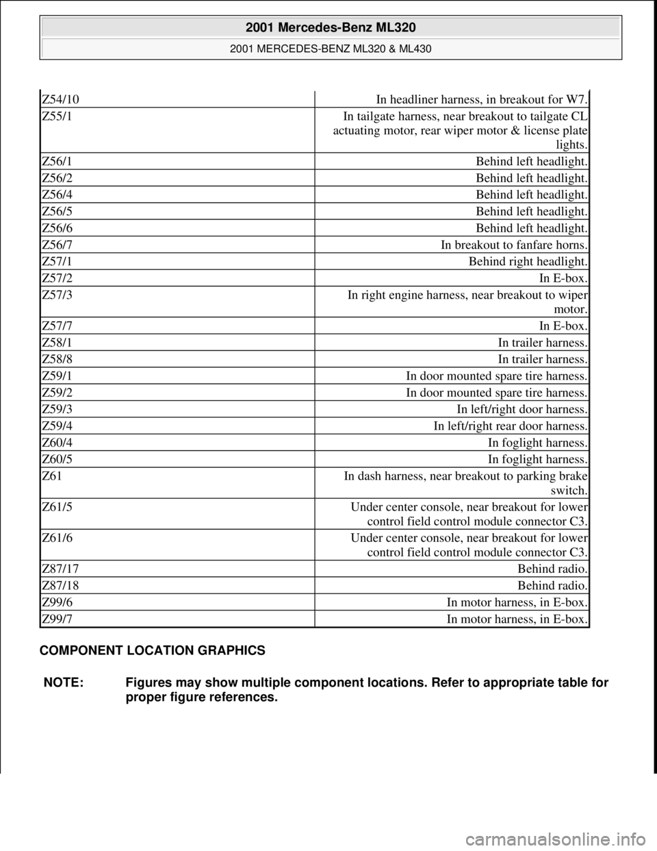
COMPONENT LOCATION GRAPHICS
Z54/10In headliner harness, in breakout for W7.
Z55/1In tailgate harness, near breakout to tailgate CL
actuating motor, rear wiper motor & license plate
lights.
Z56/1Behind left headlight.
Z56/2Behind left headlight.
Z56/4Behind left headlight.
Z56/5Behind left headlight.
Z56/6Behind left headlight.
Z56/7In breakout to fanfare horns.
Z57/1Behind right headlight.
Z57/2In E-box.
Z57/3In right engine harness, near breakout to wiper
motor.
Z57/7In E-box.
Z58/1In trailer harness.
Z58/8In trailer harness.
Z59/1In door mounted spare tire harness.
Z59/2In door mounted spare tire harness.
Z59/3In left/right door harness.
Z59/4In left/right rear door harness.
Z60/4In foglight harness.
Z60/5In foglight harness.
Z61In dash harness, near breakout to parking brake
switch.
Z61/5Under center console, near breakout for lower
control field control module connector C3.
Z61/6Under center console, near breakout for lower
control field control module connector C3.
Z87/17Behind radio.
Z87/18Behind radio.
Z99/6In motor harness, in E-box.
Z99/7In motor harness, in E-box.
NOTE: Figures may show multiple component locations. Refer to appropriate table for
proper figure references.
2001 Mercedes-Benz ML320
2001 MERCEDES-BENZ ML320 & ML430
me
Saturday, October 02, 2010 3:21:17 PMPage 12 © 2006 Mitchell Repair Information Company, LLC.
Page 3248 of 4133

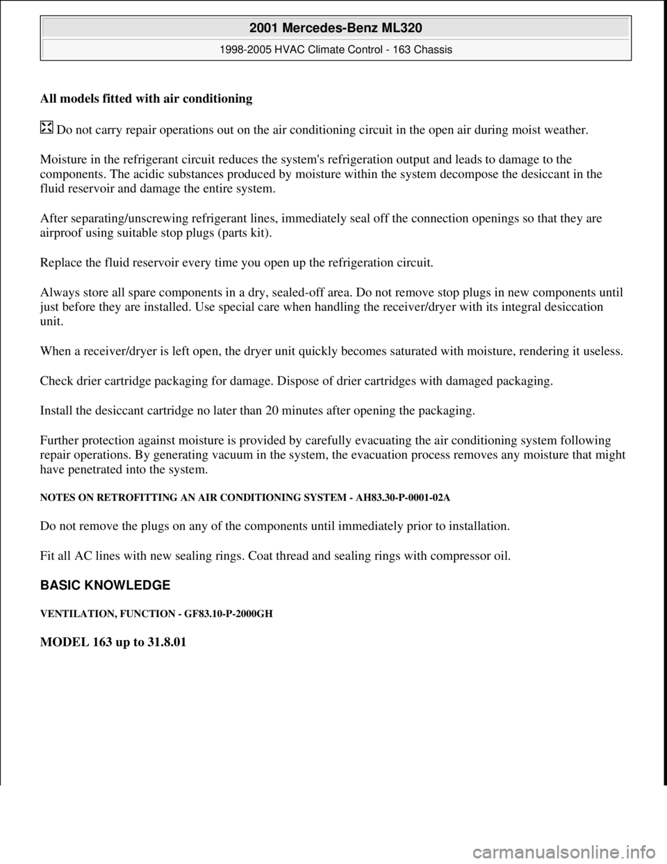
All models fitted with air conditioning
Do not carry repair operations out on the air conditioning circuit in the open air during moist weather.
Moisture in the refrigerant circuit reduces the system's refrigeration output and leads to damage to the
components. The acidic substances produced by moisture within the system decompose the desiccant in the
fluid reservoir and damage the entire system.
After separating/unscrewing refrigerant lines, immediately seal off the connection openings so that they are
airproof using suitable stop plugs (parts kit).
Replace the fluid reservoir every time you open up the refrigeration circuit.
Always store all spare components in a dry, sealed-off area. Do not remove stop plugs in new components until
just before they are installed. Use special care when handling the receiver/dryer with its integral desiccation
unit.
When a receiver/dryer is left open, the dryer unit quickly becomes saturated with moisture, rendering it useless.
Check drier cartridge packaging for damage. Dispose of drier cartridges with damaged packaging.
Install the desiccant cartridge no later than 20 minutes after opening the packaging.
Further protection against moisture is provided by carefully evacuating the air conditioning system following
repair operations. By generating vacuum in the system, the evacuation process removes any moisture that might
have penetrated into the system.
NOTES ON RETROFITTING AN AIR CONDITIONING SYSTEM - AH83.30-P-0001-02A
Do not remove the plugs on any of the components until immediately prior to installation.
Fit all AC lines with new sealing rings. Coat thread and sealing rings with compressor oil.
BASIC KNOWLEDGE
VENTILATION, FUNCTION - GF83.10-P-2000GH
MODEL 163 up to 31.8.01
2001 Mercedes-Benz ML320
1998-2005 HVAC Climate Control - 163 Chassis
me
Saturday, October 02, 2010 3:23:14 PMPage 4 © 2006 Mitchell Repair Information Company, LLC.
Page 3485 of 4133

Rims
D
When changing wheels, for instance, when replacing steel
wheels with light-alloy rims, ensure that the wheel bolts
required for the spare wheel are stored in a clearly visible
location.
D
Since December 1994 models 202 and 124 with special
equipment light alloy disk wheels, are supplied with a sheet
steel spare wheel instead of a light alloy spare wheel. The
necessary wheel bolts are included with the steel spare wheel.
D
Only use approved Mercedes-Benz rims of the same version.
D
Reinforced steel rims are identified by a sticker on the wheel
disc.
D
The wheel bolts on steel and light-alloy rims should always be
tightened to the specified tightening torque using a torque
wrench.
It is not necessary to retorque the lug bolts after approximately
100 to 500 km.
D
The seat for the tire bead must display no corrosion marks.
D
Before inserting a new rubber valve, clean the contact surfaces
on the disk wheel.
On sheet steel-disk wheel wheel trims must be fitted to support
the rubber valve.
Damaged or deformed rims must not be repaired.
Tire pressure monitor
D
Before replacing a tire, check the date of manufacturer of the
wheel sensor: wheel sensors which are more than 5 years old
must be replaced.
D
Use STAR DIAGNOSIS to read out the actual values of the tire
pressure monitor. Check the remaining life of the wheel sensor
battery, replace the wheel sensor if necessary.
Copyright DaimlerChrysler AG 06.07.2006 CD-Ausgabe G/10/04 . This WIS print-out will not be recorde
d by Modification services.
Page 2
Page 3777 of 4133

AR40.10-P-1030A
Replace tire
27.1.95
MODELS
124, 129, 140, 163, 168, 170, 171, 202, 203, 208, 209, 210, 211, 215, 220, 230, 240
MODEL
414
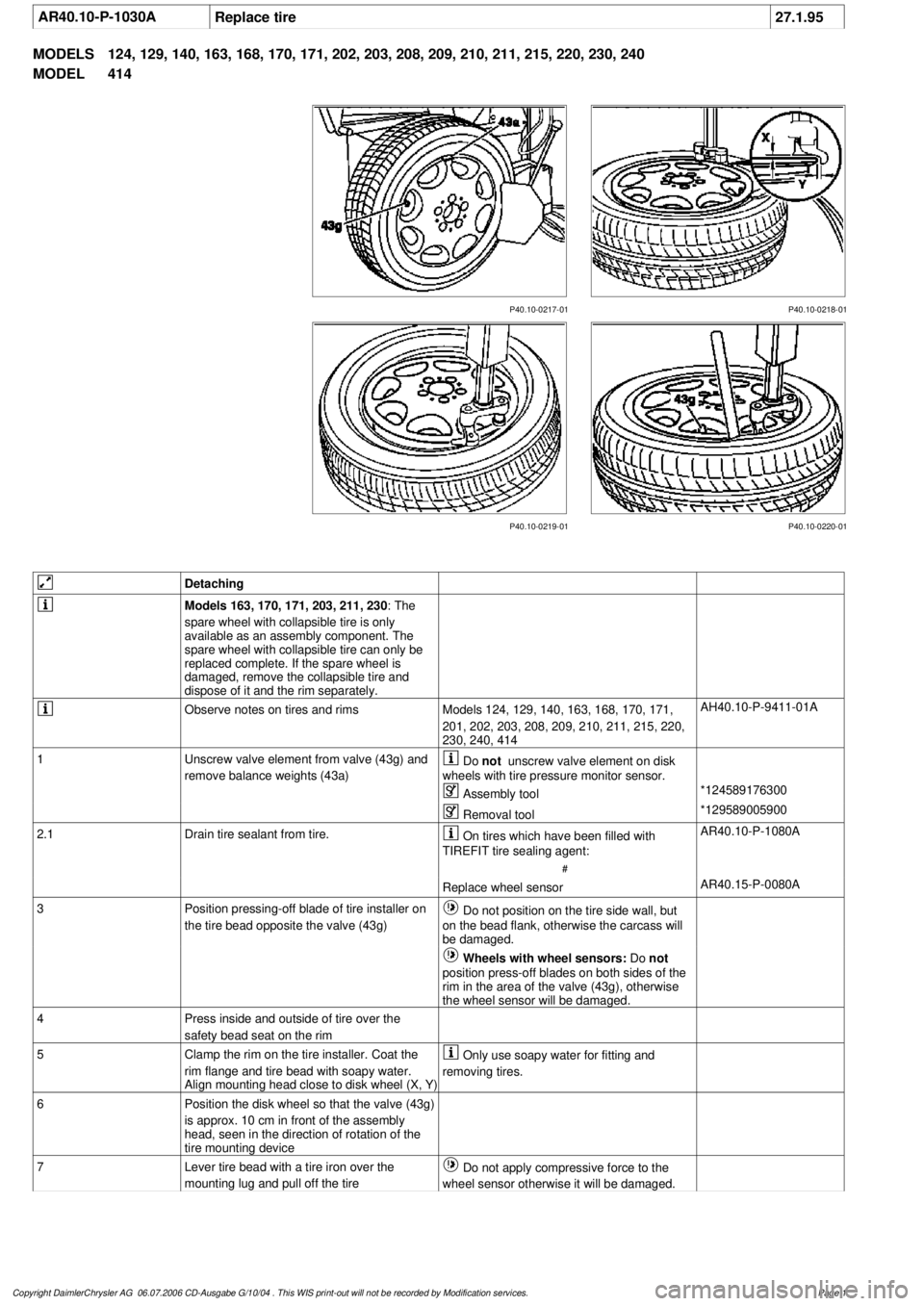
P40.10-0218-01
P40.10-0217-01
P40.10-0219-01 P40.10-0220-01
Detaching
Models 163, 170, 171, 203, 211, 230
: The
spare wheel with collapsible tire is only
available as an assembly component. The
spare wheel with collapsible tire can only be
replaced complete. If the spare wheel is
damaged, remove the collapsible tire and
dispose of it and the rim separately.
Observe notes on tires and rims
Models 124, 129, 140, 163, 168, 170, 171,
201, 202, 203, 208, 209, 210, 211, 215, 220,
230, 240, 414
AH40.10-P-9411-01A
1
Unscrew valve element from valve (43g) and
remove balance weights (43a)
Do
not
unscrew valve element on disk
wheels with tire pressure monitor sensor.
Assembly tool
*124589176300
Removal tool
*129589005900
2.1
Drain tire sealant from tire.
On tires which have been filled with
TIREFIT tire sealing agent:
#
AR40.10-P-1080A
Replace wheel sensor
AR40.15-P-0080A
3
Position pressing-off blade of tire installer on
the tire bead opposite the valve (43g)
Do not position on the tire side wall, but
on the bead flank, otherwise the carcass will
be damaged.
Wheels with wheel sensors:
Do
not
position press-off blades on both sides of the
rim in the area of the valve (43g), otherwise
the wheel sensor will be damaged.
4
Press inside and outside of tire over the
safety bead seat on the rim
5
Clamp the rim on the tire installer. Coat the
rim flange and tire bead with soapy water.
Align mounting head close to disk wheel (X, Y)
Only use soapy water for fitting and
removing tires.
6
Position the disk wheel so that the valve (43g)
is approx. 10 cm in front of the assembly
head, seen in the direction of rotation of the
tire mounting device
7
Lever tire bead with a tire iron over the
mounting lug and pull off the tire
Do not apply compressive force to the
wheel sensor otherwise it will be damaged.
Copyright DaimlerChrysler AG 06.07.2006 CD-Ausgabe G/10/04 . This WIS print-out will not be recorde
d by Modification services.
Page 1