1997 MERCEDES-BENZ ML430 warning
[x] Cancel search: warningPage 1141 of 4133

337 Index
Sun visor 132
Supplemental Restraint System
(SRS) 314
Switching off
Automatic climate control 137
ESP 81
Hazard warning flasher 112
Headlamps 54
Rapid seat heating 99
Transmission control – LOW RANGE
mode 125
Switching on
Automatic climate control 137
ESP 82
Front fog lamps 111
Front fog lamps, rear fog lamp 111
Hazard warning flasher 112
Headlamps 48
High beams 110
Rapid seat heating* 98
Seat heating* 98
Transmission control – LOW RANGE
mode 125
Trip computer* 186
Windshield wipers 49Synchronizing
ESP 246
Power windows 146
Remote control 263
Sliding/pop-up roof* 149
T
Tachometer 26, 118
Displaying gear range 121
Tail lamps 270
Cleaning 236
Replacing bulbs 267Tar stains 235
Technical data 302
Brake fluid 302
Coolants 304
Electrical system 297
Engine 294
Engine oil 302
Engine oil additives 302
Fuel requirements 303
Gasoline additives 303
Main dimensions 298
Premium unleaded gasoline 303
Rims and tires 295
Weights 299
Windshield and headlamp washer
system 307
Tele Aid System* 315
Page 1144 of 4133
340 IndexUseful features 164
Ashtrays and cigarette lighter 168
Cup holder 166
Electrical outlet 170
Garage door opener 180
Interior storage spaces 164
Programming or reprogramming the in-
tegrated remote control 182
Tele Aid* 171
Telephone* 170
Trip computer* 186
V
Vehicle
Locking 28
Locking in an emergency 262
Lowering 276
Proper use of 17
Service battery 278
Towing 283
Unlocking 28
Unlocking in an emergency 261
Vehicle and trailer weights and
ratings 207
Vehicle battery 278Vehicle care
Cup holder 238
Engine cleaning 236
Gear selector lever 238
Hard plastic trim items 238
Headlamps 236
Instrument cluster 238
Leather upholstery 239
Light alloy wheels 238
MB Tex upholstery 239
Ornamental moldings 236
Paintwork 235
Parktronic* system sensor 237
Plastic and rubber parts 239
Power washer 235
Seat belts 238
Steering wheel 238
Tail lamps 236
Tar stains 235
Turn signals 236
Upholstery 239
Vehicle washing 236
Window cleaning 237
Wiper blades 237Vehicle identification number (VIN) 292
Vehicle jack 258
Vehicle lighting
Checking 216
Vehicle tool kit 257
Vehicle with CD-changer* 258
Vehicle washing 236
VIN (Vehicle Identification Number) 292,
315
Voice control system* 315
W
Warning indicators
Parktronic* 155
Warning sounds
Drivers seat belts 64
Parking brake 48
Warranty coverage 291
Washer fluid see Windshield washer fluid
Washing the vehicle 234
Page 1147 of 4133
Service and Literature
Your authorized Mercedes-Benz Center has trained technicians and original Mercedes-Benz parts to service your vehicle properly. For
expert advice and quality service, see your authorized Mercedes-Benz Light Truck Center.
If you are interested in obtaining service literature for your vehicle, please contact your authorized Mercedes-Benz Light Truck Center.
We consider this the best way for you to obtain accurate information for your vehicle.
For further information you can find us on the Mercedes-Benz web-site www.mbusa.com or www.mercedes-benz.ca.
We reserve the right to modify the technical details of the vehicle as given in the data and illustrations of this Operator’s Manual.
Reprinting, translation and copying, even of excerpts, is not permitted without our prior authorization in writing.
Title illustration no. P00.01-2273-31
Press time 08 / 20 / 03
GSP / TIP
Printed in Germany
Warning!
G
To help avoid personal injury, be extremely careful when performing any service work or repairs. Improper or incomplete service or the use of
incorrect or inappropriate parts or materials may damage the vehicle or its equipment, which may in turn result in personal injury.
If you have questions about carrying out any type of service, turn to the advice of an authorized Mercedes-Benz Light Truck Center.
Page 1150 of 4133

GF54.30-P-3010A
Function of acoustic warnings
24.10.96
MODEL
129, 140 as of 1.6.96,
163, 168, 170,
202 as of 1.8.96,
208 up to 31.7.99,
210 as of 1.6.96 up to 30.6.99
Display
Function
Turn signal indicator
ticking
Switching on the turn signal indicator is
indicated acoustically by the turn signal
indicator ticking. The driver's attention is
brought to a defect in the turn signal system
by the turn signal indicator ticking at a higher
frequency.
Turn signal indicator ticking is generated
electromagnetically. The frequency
corresponds to that of the turn signal indicator
lamp.
The signal comes from the combination relay
(turn signal indicator with trailer coupling, rear
window defroster), wiper motor, ATA (N10/2),
on model 210 from the multi-function control
module (N10-1) or from the driver-side signal-
acquisition and actuation module (SAM)
(N10/1), on model 163 from the All-Activity
Module (AAM, N10), on model 168 it is
generated by the integrated turn signal
indicator control in the instrument cluster (A1).
Parking brake reminderThe parking brake warning sounds when
terminal 15g is ON from a speed of approx. 5
km/h.
Piezoelectric loudspeaker (quartz), function
GF54.30-P-3017A
Gear warning, model 168
only with automatic
transmission or automatic
clutch
The acoustic gear warning is active, when
D
a gear is engaged
and
D
the brake is
not
depressed
and
D
the accelerator pedal is
not
pressed
and
D
the driver's door is opened.
These conditions are processed in the gear
recognition module (A61) or in the automatic
clutch control module (N15/4). The
information on the status of the driver's door
is available as a CAN message. It is
transmitted by the instrument cluster (A1).
Piezoelectric loudspeaker (quartz), function
GF54.30-P-3017A
Speed warning
The speed warning sounds when terminal
15g is ON from a speed of approx. 120 km/h.
(on national variants only)
Piezoelectric loudspeaker (quartz), function
GF54.30-P-3017A
Speed limit warning
The warning sounds if the set maximum
speed is exceeded by at least 6 km/h.
(on vehicles with variable cruise control only)
Piezoelectric loudspeaker (quartz), function
GF54.30-P-3017A
Seat belt reminder
On national variants only
Piezoelectric loudspeaker (quartz), function
GF54.30-P-3017A
Switched-on lights
reminder
The switched-on lights reminder sounds when
terminal 15g is OFF, terminal 58k is ON,
when the starter key is removed and the
driver's door is opened.
Piezoelectric loudspeaker (quartz), function
GF54.30-P-3017A
Key reminder
The key reminder when terminal 15g is OFF
and the driver's door is open when the starter
key is inserted
Piezoelectric loudspeaker (quartz), function
GF54.30-P-3017A
Soft top reminder, model
170 only
The soft top reminder sounds when terminal
15 is ON and soft top reminder input is on low
level.
Piezoelectric loudspeaker (quartz), function
GF54.30-P-3017A
Copyright DaimlerChrysler AG 05.06.2006 CD-Ausgabe G/10/04 . This WIS print-out will not be recorde
d by Modification services.
Page 1
Page 1558 of 4133
and for reading and loading navigation data from navigation data CDs.
A special navigation CD must be inserted for navigation purposes.
The CD player integrated into the radio and navigation unit (A2/56) provides the following audio functions:
Fast forward or reverse (music search) The music played is audible during fast forward or reverse.
"Scan" function
Each track on a CD is played for 8 s. After a complete run through, the scan function is automatically
terminated.
"Random" function
All the tracks on a CD are played according to a random selection.
"Repeat" function
The current track is repeated.
"Display" function
The number and elapsed playing time for the current track, the total playing time and the number of tracks
on the CD are displayed.
Each CD includes a permanently stored table of contents (TOC record). The table of contents (TOC entry)
contains information such as the number of tracks on a CD and the CD's total playing time.
CD playback is automatically interrupted by the following functions (pause function):
Traffic messages and public warning messages over the radio data system (RDS)
Incoming telephone calls
CD playback is continued at the position at which the interruption took place. No part of the track is skipped
during the pause function.
The CD playback volume is only reduced during navigation system voice output.
CD player with changer,
location/task/design/ functionModels 209.3/4GF82.64-P-3113Q
Models 203.0/2/7
with code (819) CD
changer 6 discGF82.64-P-3113PA
Models 163, 208,
210 with code (819) GF82.64-P-3113B
2001 Mercedes-Benz ML320
1998-2005 ACCESSORIES & BODY, CAB Electrical System - Body - 163 Chassis
me
Saturday, October 02, 2010 3:30:05 PMPage 63 © 2006 Mitchell Repair Information Company, LLC.
Page 1630 of 4133
The data on the current navigation are stored for 12 hours after the radio (A2) is switched off.
SWITCH-ON/OFF CHARACTERISTICS, FUNCTION - GF82.85-P-2006GI
MODEL 163 as of 1.9.01 with CODE (522) Modular control system (MCS) radio USA with CODE (357)
Navigation system - additional unit with CODE (818b) Single CD player - additional unit with CODE
(491) U.S. version
Switch-on characteristics
Activation of entire system
When the ignition/starter switch is turned to position 1(c.15R, ON ) the display is switched on , if the radio
and navigation module (A2/56) has been switched on before the ignition key was removed the last time.
The radio and navigation module (A2/56) is now ready for operation. The system active before the last
switch-off (e.g. radio) is switched on and the corresponding basic menu displayed. If the radio and navigation
module (A2/56) has been switched off for longer than 60 min a warning display appears with general
specifications for using the system.
When a telephone call is received the radio and navigation module (A2/56) switches on automatically.
Behavior when rotary knob is pressed
The radio and navigation module (A2/56) can also be switched on the when the remote control ke
y (A8/1) is
removed by actuating the rotary knob.
All functions are then available for 60 min . After expiration of 60 min the radio and navigation module
(A2/56) switches off automatically.
This function can only be repeated by actuating the rotary knob again.
Switch-off characteristics
The radio and navigation module (A2/56) can be switched off by turning the ignition key to position 0 c. 15C,
OFF ).
Radio operation, function GF82.60-P-2001B
CD-player mode,
function GF82.60-P-2002B
Telephone mode,
functionModel 209GF82.85-P-2007QA
Navigation mode,
functionModel 163, 168,
170,208,210GF82.85-P-2012B
Model 203, 209GF82.85-P-2012EE
2001 Mercedes-Benz ML320
1998-2005 ACCESSORIES & BODY, CAB Electrical System - Body - 163 Chassis
me
Saturday, October 02, 2010 3:30:06 PMPage 135 © 2006 Mitchell Repair Information Company, LLC.
Page 1768 of 4133
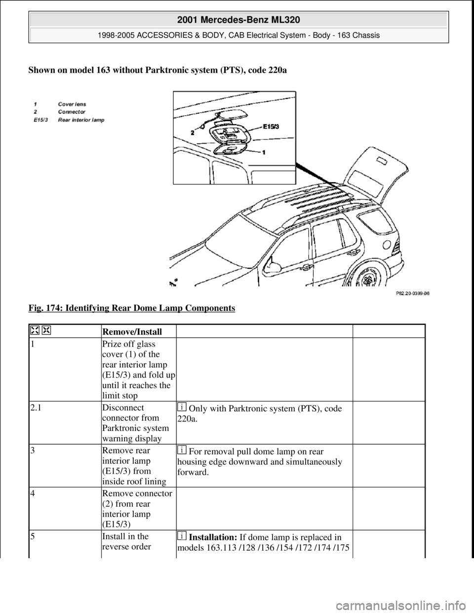
Shown on model 163 without Parktronic system (PTS), code 220a
Fig. 174: Identifying Rear Dome Lamp Components
Remove/Install
1Prize off glass
cover (1) of the
rear interior lamp
(E15/3) and fold up
until it reaches the
limit stop
2.1Disconnect
connector from
Parktronic system
warning display Only with Parktronic system (PTS), code
220a.
3Remove rear
interior lamp
(E15/3) from
inside roof lining For removal pull dome lamp on rear
housing edge downward and simultaneously
forward.
4Remove connector
(2) from rear
interior lamp
(E15/3)
5Install in the
reverse order Installation: If dome lamp is replaced in
models 163.113 /128 /136 /154 /172 /174 /175
2001 Mercedes-Benz ML320
1998-2005 ACCESSORIES & BODY, CAB Electrical System - Body - 163 Chassis
me
Saturday, October 02, 2010 3:30:09 PMPage 273 © 2006 Mitchell Repair Information Company, LLC.
Page 2034 of 4133
GF54.30-P-3007A
Charge indicator lamp, exterior lamp failure
24.10.96
MODEL
129, 140 as of 1.6.96,
163, 168, 170,
202 as of 1.8.96,
208 up to 31.7.99,
210 as of 1.6.96 up to 30.6.99
P54.30-0517-06
Terminal 61 is used for the generator
indicator lamp. When the ignition is
On
the excitation voltage is applied to it and
the generator voltage when the engine is
running.
However, a terminal is required for some
systems (e.g. exterior lamp indicator) which
D
is exactly at ground potential (low level),
when the engine is not running with the
ignition
On
D
is exactly at least 10.5 V (high level),
when the voltage at terminal 61
exceeds a particular voltage or the
engine speed exceeds a particular
threshold (480 rpm).
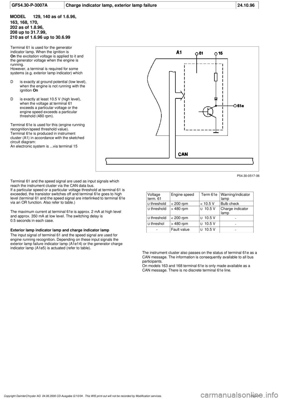
Terminal 61e is used for this (engine running
recognition/speed threshold value).
Terminal 61e is produced in instrument
cluster (A1) in accordance with the sketched
circuit diagram:
An electronic system is ...via terminal 15
Terminal 61 and the speed signal are used as input signals which
reach the instrument cluster via the CAN data bus.
If a particular speed or a particular voltage threshold at terminal 61 is
exceeded, the transistor switches off and terminal 61e goes to high
level (terminal 61 and the speed signal are interlinked to terminal 61e
via an OR function. Also refer to table.)
The maximum current at terminal 61e is approx. 2 mA at high level
and approx. 350 mA at low level. The switching delay is
0.5 seconds in each case.
Exterior lamp indicator lamp and charge indicator lamp
The input signal of terminal 61 and the speed signal are used for
engine running recognition. Depending on these input signals the
exterior lamp failure indicator lamp (A1e14) or the generator charge
indicator lamp (A1e5) is actuated (refer to table).
The instrument cluster also passes on the status of terminal 61e as a
CAN message. The information is consequently available to all bus
participants.
On models 163 and 168 terminal 61e is only made available as a
CAN message. There is no discrete terminal 61e line.
Voltage
term. 61
Engine speed
Term 61e
Warning/indicator
lamp
U
threshold
< 200 rpm
< 10.5 V
Bulb check
U
threshold
> 480 rpm
U
10.5 V
Charge indicator
lamp
U
threshold
< 200 rpm
U
10.5 V
-
U
threshol
> 480 rpm
U
10.5 V
-
-
Fault value
U
10.5 V
-
Copyright DaimlerChrysler AG 04.06.2006 CD-Ausgabe G/10/04 . This WIS print-out will not be recorde
d by Modification services.
Page 1