1997 MERCEDES-BENZ ML430 lights
[x] Cancel search: lightsPage 259 of 4133
209 Driving systems
Te ch n ica l
data Instruments
and controlsOperationDrivingInstrument
cluster displayPractical hints Car care Index Transmission control – LOW RANGE mode
The switch is located in the instrument panel.
Important!
When switching to or from the LOW RANGE mode,
observe the following:
•The vehicle must be at a complete standstill.
•The engine speed must not exceed 1500 rpm.Failure to do so may result in transmission / engine
damage not covered by the Mercedes-Benz Limited
Warranty
The LOW RANGE mode should be switched on:
•during off-road driving,
•when crossing waters.
For additional practical hints refer to off-road driving
on page 183.
Switching on:
1. Sto p t h e v e h i c l e .
2. Move transmission selector lever to position “N”.
3. Push top end of switch. The LOW RANGE indicator
lamp in the instrument cluster blinks slowly during
the changeover.
Once the changeover is complete, the indicator lamp in
the instrument cluster lights up continuously.
Note:
If the indicator lamp blinks fast, one or more switching
conditions were not observed, or the LOW RANGE mode
is defective.
Page 271 of 4133
221 Malfunction and indicator lamps
Te ch n ica l
data Instruments
and controlsOperation DrivingInstrument
cluster displayPractical hints Car care Index Electronic stability program (ESP)/Electronic
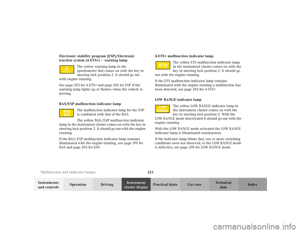
traction system (4-ETS+) — warning lamp
The yellow warning lamp in the
speedometer dial comes on with the key in
steering lock position 2. It should go out
with engine running.
See page 203 for 4-ETS+ and page 205 for ESP if the
warning lamp lights up or flashes when the vehicle is
moving.
BAS/ESP malfunction indicator lamp
The malfunction indicator lamp for the ESP
is combined with that of the BAS.
The yellow BAS / ESP malfunction indicator
lamp in the instrument cluster comes on with the key in
steering lock position 2. It should go out with the engine
running.
If the BAS / ESP malfunction indicator lamp remains
illuminated with the engine running, see page 199 for
BAS and page 205 for ESP.4-ETS+ malfunction indicator lamp
The yellow ETS malfunction indicator lamp
in the instrument cluster comes on with the
key in steering lock position 2. It should go
out with the engine running.
If the ETS malfunction indicator lamp remains
illuminated with the engine running a malfunction has
been detected, see page 203 for 4-ETS+.
LOW RANGE indicator lamp
The yellow LOW RANGE indicator lamp in
the instrument cluster comes on with the
key in steering lock position 2. With the
LOW RANGE mode deactivated it should go out with the
engine running.
With the LOW RANGE mode activated the LOW RANGE
indicator lamp is illuminated continuously.
If the indicator lamp blinks fast, one or more switching
conditions were not observed, or the LOW RANGE mode
is defective, see page 209 for LOW RANGE mode.
BAS
ESP
ETSLOW
RANGE
Page 275 of 4133
225 Malfunction and indicator lamps
Te ch n ica l
data Instruments
and controlsOperation DrivingInstrument
cluster displayPractical hints Car care Index Brake pad wear indicator lamp
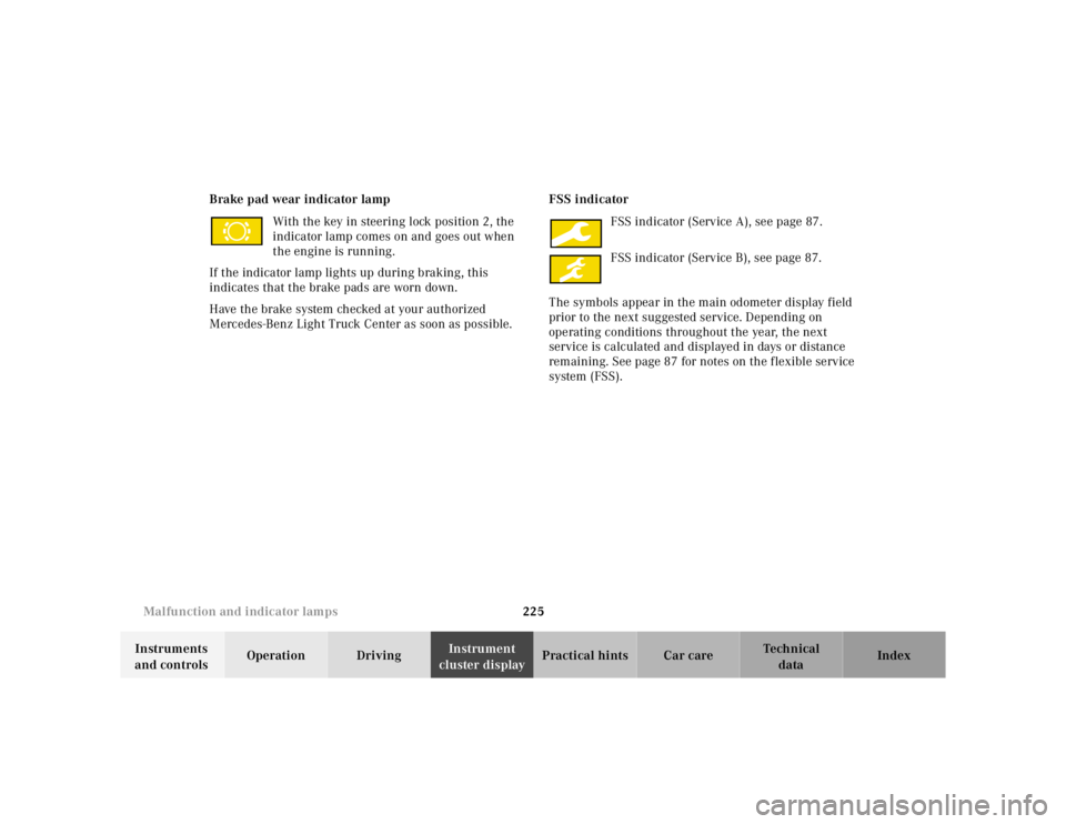
With the key in steering lock position 2, the
indicator lamp comes on and goes out when
the engine is running.
If the indicator lamp lights up during braking, this
indicates that the brake pads are worn down.
Have the brake system checked at your authorized
Mercedes-Benz Light Truck Center as soon as possible.FSS indicator
FSS indicator (Service A), see page 87.
FSS indicator (Service B), see page 87.
The symbols appear in the main odometer display field
prior to the next suggested service. Depending on
operating conditions throughout the year, the next
service is calculated and displayed in days or distance
remaining. See page 87 for notes on the flexible service
system (FSS).
Page 304 of 4133
254 Jump starting
Te ch n ica l
data Instruments
and controlsOperation DrivingInstrument
cluster displayPractical hintsCar care Index
Proceed as follows:
1. Position the vehicle with the charged battery so that
the jumper cables will reach, but never let the
vehicles touch. Make sure the jumper cables do not
have loose or missing insulation.
2. On both vehicles:
•Turn off engine and all lights and accessories,
except hazard warning flashers or work lights.
•Apply parking brake and shift selector lever to
position “P”.
Important!
3. Clamp one end of the first jumper cable to the
positive (+) under hood terminal of the discharged
battery and the other end to the positive (+) terminal
of the charged battery. Make sure the cable clamps
do not touch any other metal parts.
4. Clamp one end of the second jumper cable to the
grounded negative (–) terminal of the charged
battery and the final connection to the negative (–)
terminal of the discharged battery.Important!
5. Start engine of the vehicle with the charged battery
and run at high idle. Make sure the cables are not
on or near pulleys, fans, or other parts that move
when the engine is started. Allow the discharged
battery to charge for a few minutes. Start engine of
the disabled vehicle in the usual manner.
6. After the engine has started, remove jumper cables
by exactly reversing the above installation
sequence, starting with the last connection made
first. When removing each clamp, make sure that it
does not touch any other metal while the other end
is still attached.
Notes:
If engine does not run after several unsuccessful
starting attempts, have it checked at the nearest
authorized Mercedes-Benz Light Truck Center.
Excessive unburned fuel may damage the catalytic
converter.
Page 355 of 4133
305 Index
Te ch n ica l
data Instruments
and controlsOperation DrivingInstrument
cluster displayPractical hints Car careIndex Headlamp cleaning system ............................................ 94
Headlights ......................................................................... 90
Heated seats ..................................................................... 44
Hood ................................................................................. 231
Hooks ............................................................................... 133
IIdentification labels .......................................................285
Illuminated vanity mirrors ............................................113
Indicator lamps in the instrument cluster ................... 78
Infant and child restraint system
Installation ................................................................... 67
Infant and child restraint systems ................................ 65
Inflating the space-saver tire .......................................249
Information call
See Tele Aid ............................................................... 148
Instrument cluster ........................................................... 76
Activating display ....................................................... 80
Display illumination ................................................... 80
Indicator lamps ........................................................... 78
Malfunction and indicator lamps ........................... 218
Instrument lamps ............................................................ 80Instruments and controls ............................................... 18
Interior
General notes ............................................................. 114
Interior lighting .............................................................. 110
JJump starting ................................................................. 253KKeys, vehicle .....................................................................24LLamps, exterior .............................................................. 260
Adjusting headlamp aim ......................................... 268
Auxiliary fog lamp ............................................. 92, 264
Fog lamps .....................................................................93
Headlamp assembly ......................................... 261, 262
Headlamps .................................90, 261, 262, 268, 280
High mounted stop lamp ......................................... 267
License plate lamps ................................................. 267
Low and high beam ............................................90, 263
Page 495 of 4133

28
Central locking system
Te ch n ica l
data
Instruments
and controls Operation
Driving Instrument
cluster display Practical hints Car care Index
Locking:
Press transmit button ‹ once. All turn signal lamps
blink three times to indicate that the vehicle is locked
and the antitheft alarm is activated.
Notes:
If the turn signal lamps do not blink three times when
locking the vehicle, a door, the liftgate, or the hood is
not properly closed. Close the respective element and
lock the vehicle again with the remote control.
If the vehicle cannot be locked or unlocked by pressing
the transmit button, then it may be necessary to change
the batteries in the remote control or to synchronize the
remote control, see page 270 and page 271.
Unlocking the liftgate
Press transmit button Š to unlock the liftgate. This
also deactivates the antitheft alarm.
Important!
A minimum height clearance of 7 ft. (2.15 m) is
required to open the liftgate. Panic button
To activate press and hold button (1) for at least one
second. An audible alarm and blinking turn signal
lamps will operate for approximately 3 minutes.
Additionally the interior lights switch on automatically
for approximately 3 minutes.
To deactivate press button (1) again, or press transmit
button ‹, Œ orŠ on the remote control, or
turn key in steering lock to position 1.
Page 500 of 4133
33
Central locking system
Te ch n ica l
data
Instruments
and controls Operation
Driving Instrument
cluster display Practical hints Car care Index
Notes:
If doors are unlocked with the central locking switch
after activating the automatic central locking, and
neither door is opened, then the doors remain unlocked
even at vehicle speeds of approximately 9 mph
(15 km / h) or more.
If a door is opened from the inside at speeds of
approximately 9mph (15km/h) or less with the
automatic central locking activated, the door will again
be automatically locked at speeds of approximately
9 mph (15 km / h) or more.
Important!
When towing the vehicle, or with the vehicle on a
dynamometer test stand, please, note the following:
With the engine running, the vehicle doors will lock if
the left front wheel spins at vehicle speeds of
approximately 9 mph (15 km / h) or more.
To prevent vehicle door locks from locking, deactivate
the automatic central locking. Emergency unlocking in case of accident
The doors unlock automatically a short time after an
accident in which an airbag or emergency tensioning
retractor deploys (this is intended to aid rescue and
exit). However, the key must still be in the steering lock
position 1 or 2.
Additionally the hazard warning flashers turn on
automatically and the interior lights switch on for
approximately 30 minutes.
Page 502 of 4133
35
Antitheft alarm system
Te ch n ica l
data
Instruments
and controls Operation
Driving Instrument
cluster display Practical hints Car care Index
Antitheft alarm system
The indicator lamp is located in the center console.
The antitheft alarm is automatically armed or disarmed
with the remote control by locking or unlocking the
vehicle.
The antitheft alarm is armed within approximately
15 seconds after locking the vehicle with the remote
control.
A blinking lamp in the center console indicates that the
alarm is armed.
Notes:
Use of the key in the front door locks does not arm or
disarm the antitheft alarm system.
The alarm sounds when unlocking the driver’s door
with the mechanical key. Cancel alarm by turning key in
steering lock to position 1, or with the remote control by
pressing button Œ.
If the vehicle battery voltage falls below 10 volts, the
alarm is automatically canceled and the antitheft alarm
system is disarmed. When the voltage is above this
value again, the antitheft alarm system is armed again. Operation:
Once the alarm system has been armed, the turn signal
lamps will flash rapidly (approximately 3 minutes) and
the horn will sound intermittently (approximately
30 seconds) when someone:
• opens a door,
• opens the liftgate,
• opens the hood,
• breaks a window,
• attempts to raise the vehicle.
The alarm will stay on even if the activating element (a
door, for example) is immediately closed.
If the alarm stays on for more than 20 seconds, an
emergency call is initiated automatically. See Tele Aid
on page 148.
Note:
The alarm system will cycle three times when triggered.
The interior lights are automatically switched on when
the alarm comes on and go out when canceling the
alarm.