1997 MERCEDES-BENZ ML430 check engine light
[x] Cancel search: check engine lightPage 2383 of 4133
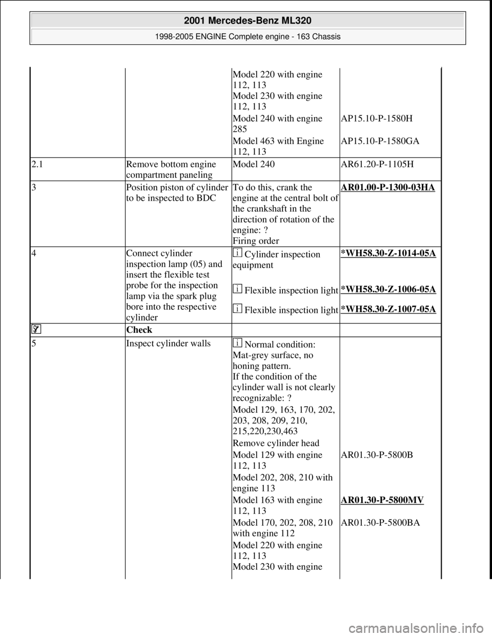
Model 220 with engine
112, 113
Model 230 with engine
112, 113
Model 240 with engine
285AP15.10-P-1580H
Model 463 with Engine
112, 113AP15.10-P-1580GA
2.1Remove bottom engine
compartment panelingModel 240AR61.20-P-1105H
3Position piston of cylinder
to be inspected to BDCTo do this, crank the
engine at the central bolt of
the crankshaft in the
direction of rotation of the
engine: ?
Firing orderAR01.00-P-1300-03HA
4Connect cylinder
inspection lamp (05) and
insert the flexible test
probe for the inspection
lamp via the spark plug
bore into the respective
cylinder Cylinder inspection
equipment*WH58.30-Z-1014-05A
Flexible inspection light*WH58.30-Z-1006-05A
Flexible inspection light*WH58.30-Z-1007-05A
Check
5Inspect cylinder walls Normal condition:
Mat-grey surface, no
honing pattern.
If the condition of the
cylinder wall is not clearly
recognizable: ?
Model 129, 163, 170, 202,
203, 208, 209, 210,
215,220,230,463
Remove cylinder head
Model 129 with engine
112, 113AR01.30-P-5800B
Model 202, 208, 210 with
engine 113
Model 163 with engine
112, 113AR01.30-P-5800MV
Model 170, 202, 208, 210
with engine 112AR01.30-P-5800BA
Model 220 with engine
112, 113
Model 230 with engine
2001 Mercedes-Benz ML320
1998-2005 ENGINE Complete engine - 163 Chassis
me
Saturday, October 02, 2010 3:17:56 PMPage 27 © 2006 Mitchell Repair Information Company, LLC.
Page 3186 of 4133
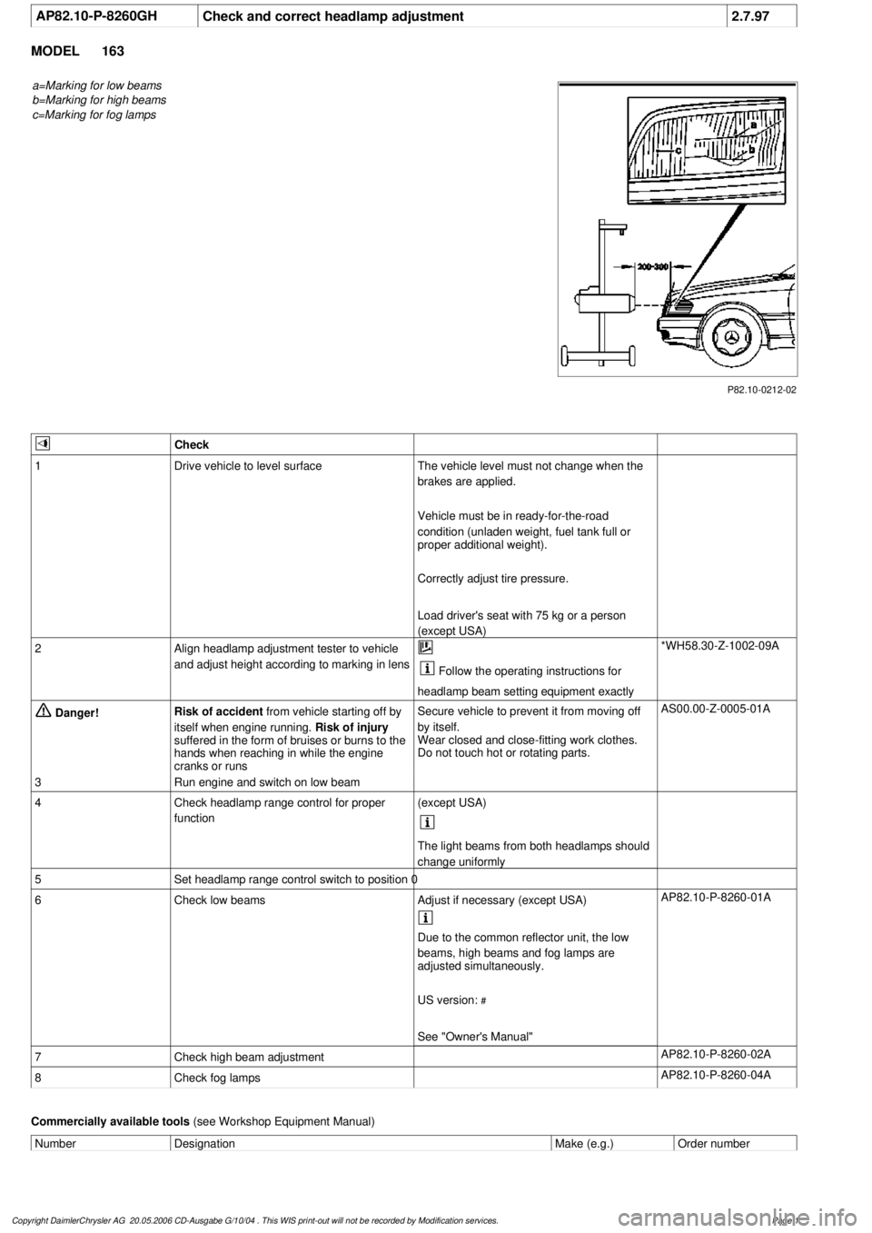
AP82.10-P-8260GH
Check and correct headlamp adjustment
2.7.97
MODEL
163
a=Marking for low beams
b=Marking for high beams
c=Marking for fog lamps
P82.10-0212-02
Check
1
Drive vehicle to level surface
The vehicle level must not change when the
brakes are applied.
Vehicle must be in ready-for-the-road
condition (unladen weight, fuel tank full or
proper additional weight).
Correctly adjust tire pressure.
Load driver's seat with 75 kg or a person
(except USA)
2
Align headlamp adjustment tester to vehicle
and adjust height according to marking in lens
Follow the operating instructions for
headlamp beam setting equipment exactly
*WH58.30-Z-1002-09A
Danger!
Risk of accident
from vehicle starting off by
itself when engine running.
Risk of injury
suffered in the form of bruises or burns to the
hands when reaching in while the engine
cranks or runs
Secure vehicle to prevent it from moving off
by itself.
Wear closed and close-fitting work clothes.
Do not touch hot or rotating parts.
AS00.00-Z-0005-01A
3
Run engine and switch on low beam
4
Check headlamp range control for proper
function
(except USA)
The light beams from both headlamps should
change uniformly
5
Set headlamp range control switch to position 0
6
Check low beams
Adjust if necessary (except USA)
AP82.10-P-8260-01A
Due to the common reflector unit, the low
beams, high beams and fog lamps are
adjusted simultaneously.
US version:
#
See "Owner's Manual"
7
Check high beam adjustment
AP82.10-P-8260-02A
8
Check fog lamps
AP82.10-P-8260-04A
Commercially available tools
(see Workshop Equipment Manual)
Number
Designation
Make (e.g.)
Order number
Copyright DaimlerChrysler AG 20.05.2006 CD-Ausgabe G/10/04 . This WIS print-out will not be recorde
d by Modification services.
Page 1
Page 3190 of 4133

AF18.00-P-8044D
High oil consumption
12.3.01
ENGINE
112 in MODEL 129, 163, 170, 202, 203, 208, 210, 220
ENGINE
113 in MODEL 129, 163, 202, 208, 210, 215, 220
ENGINE
112, 113 in MODEL 463
Damage code
Cause
Remedy
Studies on engines 112/113 due to
excessive engine oil consumption have
indicated to date that excessive engine oil
consumption is not a general subject, but
rather can result from various causes.
The causes listed below may cause
excessive engine oil consumption individually
or in combination.
For commercially available tools for see
Workshop Equipment Manual
Cause 1:
Remedy 1:
00 001 70
Cast iron crust in right cylinder head behind
oil drain opening
1
Remove cast iron crust
AF18.00-P-8045A
Cause 2:
Remedy 2:
00 001 70
V-shaped material flaws (rough unhoned
points) on individual cylinder liners
Up to production 08/2000.
1
Check cylinder liners with piston at
bottom dead center.
#
Inspect cylinders with light probe
AR01.00-P-0200AU
*WH58.30-Z-1009-05A
*WH58.30-Z-1010-05A
*WH58.30-Z-1027-05A
Cylinder barrels not okay:
#
2
Remove/install/replace engine or
shortblock.
Cause 3:
Remedy 3:
00 001 70
Single oil scraper rings with ring tension at
lower tolerance limit.
Up to production 06/1999.
1
Perform oil consumption test drive over
approx. 500 km.
AR18.00-P-0025AV
Exclude all other types of faults.
2
Remove/install/replace piston rings.
Install cleaned pistons with new piston
rings in the same cylinder.
Install piston rings with optimized ring
tension.
These piston rings are available as
replacement parts under the normal
replacement part number.
Cause 4:
Remedy 4:
00 001 70
Individual (right) cylinder heads with inner
porous points to air injection duct.
1
Check left/right cylinder bank.
If a cylinder bank is oily:
#
2
Remove/install/replace only this cylinder
head.
ENGINE
112 in MODEL 220, 210, 208, 202,
129
ENGINE
113 in MODEL 220, 210, 208, 202,
129
AR01.30-P-5800B
ENGINE
112.942 in MODEL 163.154
ENGINE
113.942 in MODEL 163.172
ENGINE
113.981 in MODEL 163.174 AR01.30-P-5800MV
ENGINE
112.945, 113.962 in MODEL 463
AR01.30-P-5800GV
Cause 5:
Remedy 5:
00 001 70
Individual engines with missing valve seals on
individual cylinders
1
Remove valve springs on affected
cylinder.
AR05.30-P-3500B
In this case, usually one cylinder is oily, oil
runs through valve cone into cylinder when
valve is open.
2
Check valve seal.
Copyright DaimlerChrysler AG 20.05.2006 CD-Ausgabe G/10/04 . This WIS print-out will not be recorde
d by Modification services.
Page 1
Page 3191 of 4133

Valve seal not okay :
#
3
Remove/install/replace valve seal.
AR05.30-P-3500B
Cause 6:
Remedy 6:
00 001 70
1.5 mm hole missing on individual right
cylinder head covers at connection to
crankcase ventilation.
1
Check cylinder head cover
Up to production 06/1999.
Crankcase ventilation out of order, engine can
sludge up and consume oil as a result
Cylinder head cover not okay:
#
2
Remove/install/replace cylinder head
cover.
ENGINE
112
Air cleaner positioned on engine
side.
ENGINE
113
Air cleaner positioned on engine
side.
AR01.20-P-5014BV
ENGINE
112
Air cleaner positioned on engine side
ENGINE
113
Air cleaner positioned on engine side
AR01.20-P-5014B
Cause 7:
Remedy 7:
00 001 70
Engine oil sludging due to excessively long
engine oil change intervals
Service information: Oil sludge
SI18.00-P-0010A
If the service interval according to
ASSYST is exceeded, the engine oil sludges
up sooner or later depending on the oil
quality, type of operation and operating time.
Engine consumes oil.
See Service Information.
1
Print out ASSYST printout.
2
Check oil change intervals
3
Inform vehicle owner.
4
Remove/install/replace piston rings.
AR03.10-P-7311BV
Disassemble and clean sludged engines
completely because dirty oil usually gets into
clean-oil side due to clogged oil filter.
Cause 8:
Remedy 8:
00 001 70
Piston rings sticky or have coke deposits from
engine oils (e.g. API-S in USA) in connection
with regionally poor fuel quality.
Always use engine oils according to
Specifications for Operating Fluids 229.3, do
not add special additives to engine oil and fuel
BB00.40-P-0229-03A
1
Remove/install/replace piston rings.
AR03.10-P-7311BV
Cause 9:
Remedy 9:
00 001 70
Piston ring wear due to excessive
contamination/dust (model 163) through air
intake system.
1
Remove/install/replace gaskets on air
intake line and distribution element of
partial load ventilation.
e.g. due to incorrect assembly after
workshop visit or embrittlement of gaskets
The distribution element with optimized
material will be available as of 11/ 2000 as a
standard feature.
2
Remove/install/replace intake module.
Exterior oil loss, e.g. due to cast iron
porosity on left side of crankcase in area of
engine support is not considered to be oil
consumption
In the event of a customer complaint
regarding the engine oil consumption, always
determine the oil consumption definitely
because the oil indicator lamp can come on
due to other causes (e.g. defective oil sensor).
Commercially available tools
(see Workshop Equipment Manual)
Number
Designation
Make (e. g.)
Order number
WH58.30-Z-1009-05A
Flexible inspection light
Scope of supply 1 (complete unit):
-glass fiber optical fiber
-light projector
-230 V, storage case
-operating instructions
-graphics protocol
Richard Wolf GmbH
Pforzheimerstr. 32
D-75438 Knittlingen
Karl Storz GmbH
Mittelstr. 8
D-78532 Tuttlingen
1.00565.00
80902
WH58.30-Z-1010-05A
Flexible inspection light
Scope of delivery 2 (for workshops which already have an approved
Wolf or Storz inspection light):
-storage case
-operating instructions
-pictures protocol
Richard Wolf GmbH
Pforzheimerstr. 32
D-75438 Knittlingen
Karl Storz GmbH
Mittelstr. 8
D-78532 Tuttlingen
7.05065.00
K03506AJ
Copyright DaimlerChrysler AG 20.05.2006 CD-Ausgabe G/10/04 . This WIS print-out will not be recorde
d by Modification services.
Page 2
Page 3201 of 4133
Danger!
Risk of explosion
from explosive gas.
Risk
of poisoning and caustic burns from
swallowing battery electrolyte.
Risk of injury
through burns to skin and eyes from battery
acid or when handling damaged lead-acid
batteries
No fire, sparks, naked flames or smoking.
Wear protective gloves, acid-resistant
clothing and safety glasses. Pour battery
electrolyte only into suitable and appropriately
marked containers.
AS54.10-Z-0001-01A
4
Remove battery
AR54.10-P-0005GH
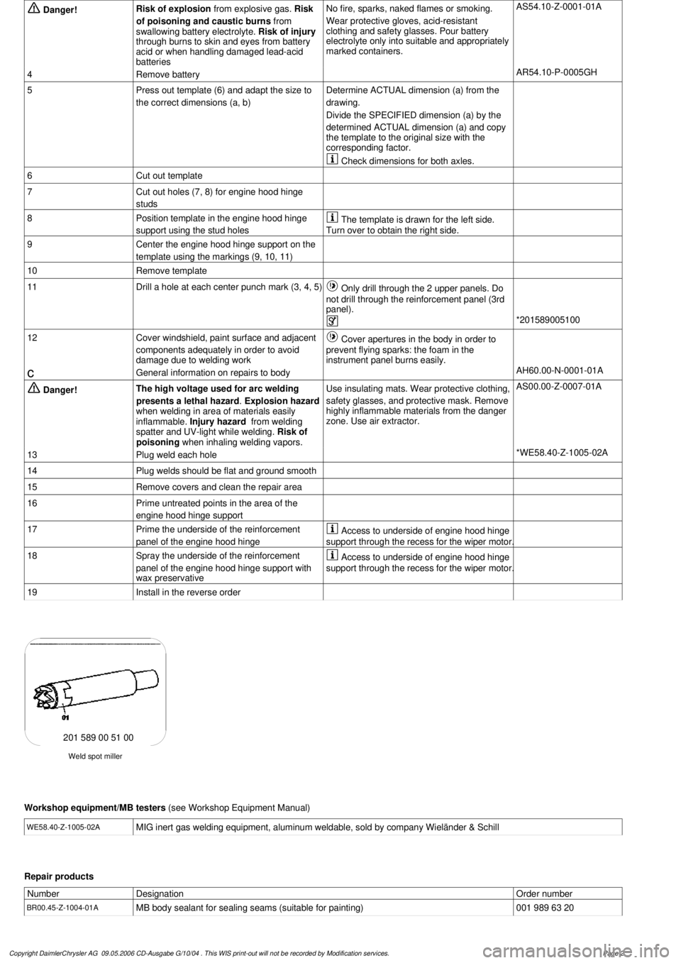
5
Press out template (6) and adapt the size to
the correct dimensions (a, b)Determine ACTUAL dimension (a) from the
drawing.
Divide the SPECIFIED dimension (a) by the
determined ACTUAL dimension (a) and copy
the template to the original size with the
corresponding factor.
Check dimensions for both axles.
6
Cut out template
7
Cut out holes (7, 8) for engine hood hinge
studs
8
Position template in the engine hood hinge
support using the stud holes
The template is drawn for the left side.
Turn over to obtain the right side.
9
Center the engine hood hinge support on the
template using the markings (9, 10, 11)
10
Remove template
11
Drill a hole at each center punch mark (3, 4, 5)
Only drill through the 2 upper panels. Do
not drill through the reinforcement panel (3rd
panel).
*201589005100
12
Cover windshield, paint surface and adjacent
components adequately in order to avoid
damage due to welding work
Cover apertures in the body in order to
prevent flying sparks: the foam in the
instrument panel burns easily.
c
General information on repairs to body
AH60.00-N-0001-01A
Danger!
The high voltage used for arc welding
presents a lethal hazard
.
Explosion hazard
when welding in area of materials easily
inflammable.
Injury hazard
from welding
spatter and UV-light while welding.
Risk of
poisoning
when inhaling welding vapors.
Use insulating mats. Wear protective clothing,
safety glasses, and protective mask.
Remove
highly inflammable materials from the danger
zone. Use air extractor.
AS00.00-Z-0007-01A
13
Plug weld each hole
*WE58.40-Z-1005-02A
14
Plug welds should be flat and ground smooth
15
Remove covers and clean the repair area
16
Prime untreated points in the area of the
engine hood hinge support
17
Prime the underside of the reinforcement
panel of the engine hood hinge
Access to underside of engine hood hinge
support through the recess for the wiper motor.
18
Spray the underside of the reinforcement
panel of the engine hood hinge support with
wax preservative
Access to underside of engine hood hinge
support through the recess for the wiper motor.
19
Install in the reverse order
Weld spot miller
201 589 00 51 00
Workshop equipment/MB testers
(see Workshop Equipment Manual)
WE58.40-Z-1005-02A
MIG inert gas welding equipment, aluminum weldable, sold by company Wieländer & Schill
Repair products
Number
Designation
Order number
BR00.45-Z-1004-01A
MB body sealant for sealing seams (suitable for painting)
001 989 63 20
Copyright DaimlerChrysler AG 09.05.2006 CD-Ausgabe G/10/04 . This WIS print-out will not be recorde
d by Modification services.
Page 2
Page 3204 of 4133
3
Remove engine hood hinge on the front
passenger side
AR88.40-P-3060GH
*BR00.45-Z-1004-01A
Danger!
Risk of explosion
from explosive gas.
Risk
of poisoning and caustic burns from
swallowing battery electrolyte.
Risk of injury
through burns to skin and eyes from battery
acid or when handling damaged lead-acid
batteries
No fire, sparks, naked flames or smoking.
Wear protective gloves, acid-resistant
clothing and safety glasses. Pour battery
electrolyte only into suitable and appropriately
marked containers.
AS54.10-Z-0001-01A
4
Remove battery
AR54.10-P-0005GH
5
Remove air conditioning blower motor
AR83.30-P-5560GH
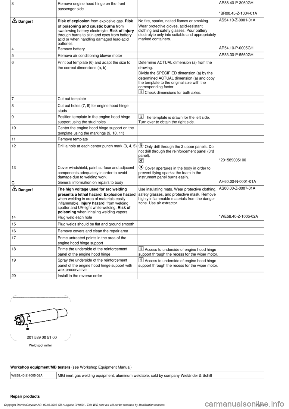
6
Print out template (6) and adapt the size to
the correct dimensions (a, b)Determine ACTUAL dimension (a) from the
drawing.
Divide the SPECIFIED dimension (a) by the
determined ACTUAL dimension (a) and copy
the template to the original size with the
corresponding factor.
Check dimensions for both axles.
7
Cut out template
8
Cut out holes (7, 8) for engine hood hinge
studs
9
Position template in the engine hood hinge
support using the stud holes
The template is drawn for the left side.
Turn over to obtain the right side.
10
Center the engine hood hinge support on the
template using the markings (9, 10, 11)
11
Remove template
12
Drill a hole at each center punch mark (3, 4, 5)
Only drill through the 2 upper panels. Do
not drill through the reinforcement panel (3rd
panel).
*201589005100
13
Cover windshield, paint surface and adjacent
components adequately in order to avoid
damage due to welding work
Cover apertures in the body in order to
prevent flying sparks: the foam in the
instrument panel burns easily.
c
General information on repairs to body
AH60.00-N-0001-01A
Danger!
The high voltage used for arc welding
presents a lethal hazard
.
Explosion hazard
when welding in area of materials easily
inflammable.
Injury hazard
from welding
spatter and UV-light while welding.
Risk of
poisoning
when inhaling welding vapors.
Use insulating mats. Wear protective clothing,
safety glasses, and protective mask.
Remove
highly inflammable materials from the danger
zone. Use air extractor.
AS00.00-Z-0007-01A
14
Plug weld each hole
*WE58.40-Z-1005-02A
15
Plug welds should be flat and ground smooth
16
Remove covers and clean the repair area
17
Prime untreated points in the area of the
engine hood hinge support
18
Prime the underside of the reinforcement
panel of the engine hood hinge
Access to underside of engine hood hinge
support through the recess for the wiper motor.
19
Spray the underside of the reinforcement
panel of the engine hood hinge support with
wax preservative
Access to underside of engine hood hinge
support through the recess for the wiper motor.
20
Install in the reverse order
Weld spot miller
201 589 00 51 00
Workshop equipment/MB testers
(see Workshop Equipment Manual)
WE58.40-Z-1005-02A
MIG inert gas welding equipment, aluminum weldable, sold by company Wieländer & Schill
Repair products
Copyright DaimlerChrysler AG 09.05.2006 CD-Ausgabe G/10/04 . This WIS print-out will not be recorde
d by Modification services.
Page 2
Page 3206 of 4133
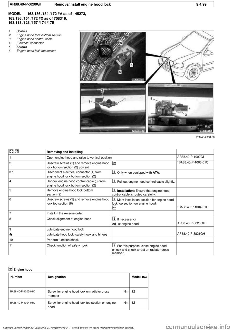
AR88.40-P-3200GI
Remove/install engine hood lock
9.4.99
MODEL
163.136 /154 /172 #A as of 145273,
163.136 /154 /172 #X as of 708319,
163.113 /128 /157 /174 /175
P88.40-2058-06
1
Screws
2
Engine hood lock bottom section
3
Engine hood control cable
4
Electrical connector
5
Screws
6
Engine hood lock top section
Removing and installing
1
Open engine hood and raise to vertical position
AR88.40-P-1000GI
2
Unscrew screws (1) and remove engine hood
lock bottom section (2) upward
*BA88.40-P-1003-01C
3.1
Disconnect electrical connector (4) from
engine hood lock bottom section (2)
Only when equipped with
ATA
.
4
Unhook engine hood control cable (3) from
engine hood lock bottom section (2)
Pull out engine hood control cable slightly.
5
Remove engine hood lock bottom
section (2)
Installation:
Ensure that engine hood
control cable is routed carefully.
6
Unscrew screws (5) and remove engine hood
lock top section (6)
Mark installation position for engine hood
lock top section on engine hood.
*BA88.40-P-1004-01C
7
Install in the reverse order
8
Check alignment of engine hood
If necessary:
#
Adjust engine hood
AR88.40-P-3020GH
9
Lubricate engine hood lock
e
Lubricate hood lock, safety hook and hinges
AP88.40-P-8821GH
10
Perform function check
11
Check function of safety hook
For this purpose, close engine hood,
unlock and check arrest on radiator cross
member.
Engine hood
Number
Designation
Model 163
BA88.40-P-1003-01C
Screw for engine hood lock on radiator cross
member
Nm
12
BA88.40-P-1004-01C
Screw for engine hood lock top section on engine
hood
Nm
12
Copyright DaimlerChrysler AG 09.05.2006 CD-Ausgabe G/10/04 . This WIS print-out will not be recorde
d by Modification services.
Page 1
Page 3208 of 4133
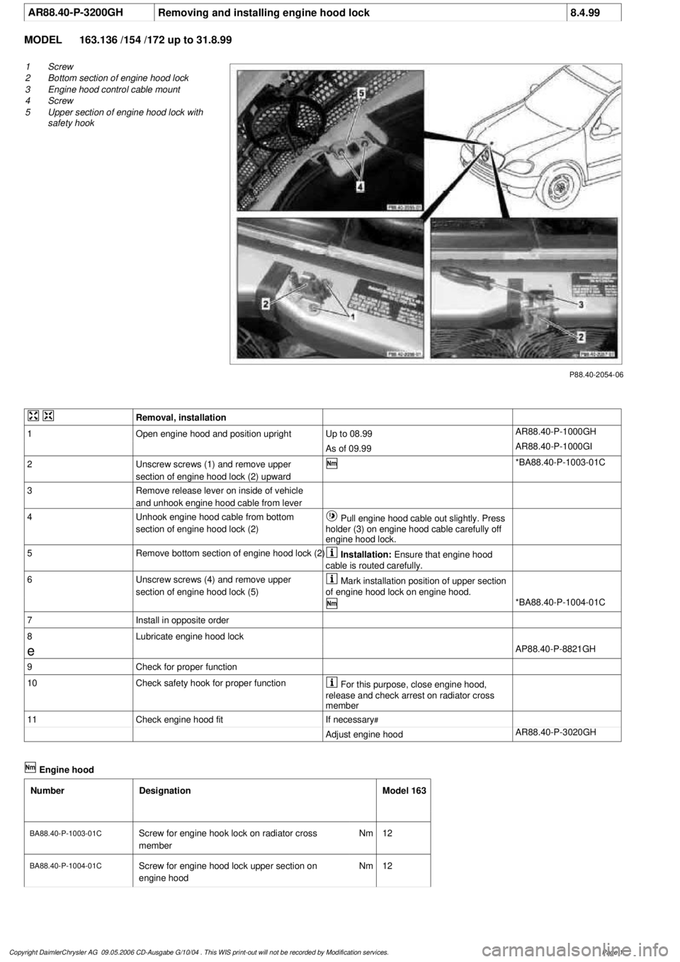
AR88.40-P-3200GH
Removing and installing engine hood lock
8.4.99
MODEL
163.136 /154 /172 up to 31.8.99
P88.40-2054-06
1
Screw
2
Bottom section of engine hood lock
3
Engine hood control cable mount
4
Screw
5
Upper section of engine hood lock with
safety hook
Removal, installation
1
Open engine hood and position upright
Up to 08.99
AR88.40-P-1000GH
As of 09.99
AR88.40-P-1000GI
2
Unscrew screws (1) and remove upper
section of engine hood lock (2) upward
*BA88.40-P-1003-01C
3
Remove release lever on inside of vehicle
and unhook engine hood cable from lever
4
Unhook engine hood cable from bottom
section of engine hood lock (2)
Pull engine hood cable out slightly. Press
holder (3) on engine hood cable carefully off
engine hood lock.
5
Remove bottom section of engine hood lock (2)
Installation:
Ensure that engine hood
cable is routed carefully.
6
Unscrew screws (4) and remove upper
section of engine hood lock (5)
Mark installation position of upper section
of engine hood lock on engine hood.
*BA88.40-P-1004-01C
7
Install in opposite order
8
Lubricate engine hood lock
e
AP88.40-P-8821GH
9
Check for proper function
10
Check safety hook for proper function
For this purpose, close engine hood,
release and check arrest on radiator cross
member
11
Check engine hood fit
If necessary
#
Adjust engine hood
AR88.40-P-3020GH
Engine hood
Number
Designation
Model 163
BA88.40-P-1003-01C
Screw for engine hook lock on radiator cross
member
Nm
12
BA88.40-P-1004-01C
Screw for engine hood lock upper section on
engine hood
Nm
12
Copyright DaimlerChrysler AG 09.05.2006 CD-Ausgabe G/10/04 . This WIS print-out will not be recorde
d by Modification services.
Page 1