Page 1929 of 4133
4. Unscrew sheet metal screws ( 30) from instrument panel.
5. Install mount (15) together with interface between mounting lugs (31) and (32) as shown in figure and
fasten with sheet metal screws (30).
6. Route connection plug for adapter wiring ha rness (D) upward into the radio recess.
Fig. 379: Identifying Mounting Lugs And Sheet Metal Screws
7. Connect portable cellular telephone wiring harn ess (2) to adapter wiring harness (9).
8. Check fuse (23) (a 10A fuse should be present).
Fig. 380: Identifying Fuse A nd Telephone Wiring Harness
9. Connect adapter wiring harness (9) to radio connector.
2001 Mercedes-Benz ML320
1998-2005 ACCESSORIES & BODY, CAB Electr ical System - Body - 163 Chassis
me
Saturday, October 02, 2010 3:30:13 PMPage 434 © 2006 Mitchell Repair Information Company, LLC.
Page 1931 of 4133
Fig. 383: Identifying Portable Cellular Telephone Wiring Harness And Components
7. Unscrew self-tapping screws (50) at instrument panel.
Insert mount with control modules from above through the radio opening.
8. Connect fiber optic cable.
9. Insert mount (15) with interface as shown in figure between the two mounting plates (51) and (52) and
attach with the self-tapping screws (50).
10. Route microphone connector (C) and adapter wiring harness connector (D) upward into radio shaft.
Fig. 384: Identifying Self
-Tapping Screws And Microphone Connector
11. Connect portable CTEL wiring harness (2) to adapter wiring harness (9).
12. Inspect fuse (23) (a 10A fuse must be fitted).
2001 Mercedes-Benz ML320
1998-2005 ACCESSORIES & BODY, CAB Electrical System - Body - 163 Chassis
me
Saturday, October 02, 2010 3:30:13 PMPage 436 © 2006 Mitchell Repair Information Company, LLC.
Page 1932 of 4133

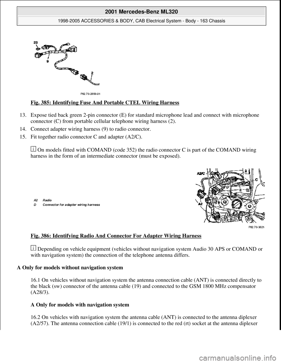
Fig. 385: Identifying Fuse And Portable CTEL Wiring Harness
13. Expose tied back green 2-pin connector (E) for standard microphone lead and connect with microphone
connector (C) from portable cellular telephone wiring harness (2).
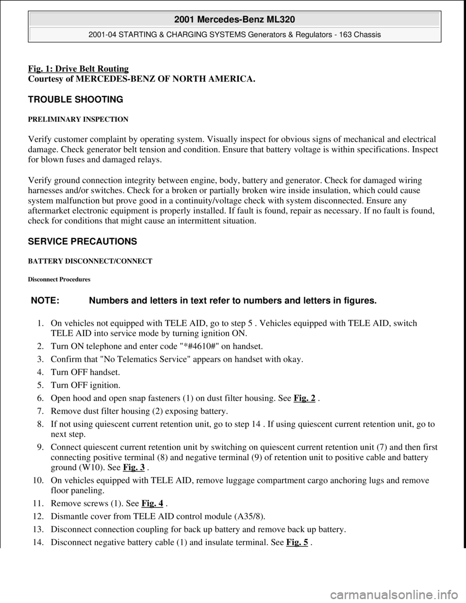
14. Connect adapter wiring harness (9) to radio connector.
15. Fit together radio connector C and adapter (A2/C).
On models fitted with COMAND (code 352) the radio connector C is part of the COMAND wiring
harness in the form of an intermediate connector (must be exposed).
Fig. 386: Identifying Radio And Connector For Adapter Wiring Harness
Depending on vehicle equipment (vehicles without navigation system Audio 30 APS or COMAND or
with navigation system) the connection of the telephone antenna differs.
A Only for models without navigation system
16.1 On vehicles without navigation system the antenna connection cable (ANT) is connected directly to
the black (sw) connector of the antenna cable (19) and connected to the GSM 1800 MHz compensator
(A28/3).
A Only for models with navigation system
16.2 On vehicles with navigation system the antenna cable (ANT) is connected to the antenna diplexer
(A2/57). The antenna connection cable (19/1) is connected to the red (rt) socket at the antenna diplexer
2001 Mercedes-Benz ML320
1998-2005 ACCESSORIES & BODY, CAB Electrical System - Body - 163 Chassis
me
Saturday, October 02, 2010 3:30:13 PMPage 437 © 2006 Mitchell Repair Information Company, LLC.
Page 1936 of 4133
Fig. 392: Locating Wiring Harness
20. Connect telephone wiring harness (2) to adapter wiring harness (9).
21. Check fuse (23) (a 10A fuse should be present).
Fig. 393: Identifying Telephone Wiring Harness To Adapter Wiring Harness Connection & Fuse
22. Connect adapter wiring harness (9) to radio wiring harness and insert into radio slot.
23. Place microphone cable of telephone wirin
g harness (2) into radio slot.
2001 Mercedes-Benz ML320
1998-2005 ACCESSORIES & BODY, CAB Electr ical System - Body - 163 Chassis
me
Saturday, October 02, 2010 3:30:14 PMPage 441 © 2006 Mitchell Repair Information Company, LLC.
Page 2028 of 4133
GF80.20-P-0005-01GH
Central locking (CL), location of components
P80.20-0522-06
Location of components
1
Antenna
F1
Fuse and relay module
F1k15
CL rear door unlocking relay
F1k20
CL all door locking relay
F1k23
CL front right front door and rear
door unlocking relay
F1k24
CL front left front door and tank
flap unlocking relay
M14/5
Right front door CL actuating
motor
M14/6
Left front door CL actuating motor
M14/7
Tailgate CL actuating motor
M14/8
Left rear door CL actuating motor
M14/9
Right rear door CL actuating motor
M14/10
Filler flap CL actuating motor
N10
All-activity module (AAM)
Copyright DaimlerChrysler AG 17.05.2006 CD-Ausgabe G/10/04 . This WIS print-out will not be recorde
d by Modification services.
Page 1
Page 2037 of 4133

Fig. 1: Drive Belt Routing
Courtesy of MERCEDES-BENZ OF NORTH AMERICA.
TROUBLE SHOOTING
PRELIMINARY INSPECTION
Verify customer complaint by operating system. Visually inspect for obvious signs of mechanical and electrical
damage. Check generator belt tension and condition. Ensure that battery voltage is within specifications. Inspect
for blown fuses and damaged relays.
Verify ground connection integrity between engine, body, battery and generator. Check for damaged wiring
harnesses and/or switches. Check for a broken or partially broken wire inside insulation, which could cause
system malfunction but prove good in a continuity/voltage check with system disconnected. Ensure any
aftermarket electronic equipment is properly installed. If fault is found, repair as necessary. If no fault is found,
check for conditions that might cause an intermittent situation.
SERVICE PRECAUTIONS
BATTERY DISCONNECT/CONNECT
Disconnect Procedures
1. On vehicles not equipped with TELE AID, go to step 5 . Vehicles equipped with TELE AID, switch
TELE AID into service mode by turning ignition ON.
2. Turn ON telephone and enter code "*#4610#" on handset.
3. Confirm that "No Telematics Service" appears on handset with okay.
4. Turn OFF handset.
5. Turn OFF ignition.
6. Open hood and open snap fasteners (1) on dust filter housing. See Fig. 2
.
7. Remove dust filter housing (2) exposing battery.
8. If not using quiescent current retention unit, go to step 14 . If using quiescent current retention unit, go to
next step.
9. Connect quiescent current retention unit by switching on quiescent current retention unit (7) and then first
connecting positive terminal (8) and negative terminal (9) of retention unit to positive cable and battery
ground (W10). See Fig. 3
.
10. On vehicles equipped with TELE AID, remove luggage compartment cargo anchoring lugs and remove
floor paneling.
11. Remove screws (1). See Fig. 4
.
12. Dismantle cover from TELE AID control module (A35/8).
13. Disconnect connection coupling for back up battery and remove back up battery.
14. Disconnect ne
gative battery cable (1) and insulate terminal. See Fig. 5. NOTE: Numbers and letters in text refer to numbers and letters in figures.
2001 Mercedes-Benz ML320
2001-04 STARTING & CHARGING SYSTEMS Generators & Regulators - 163 Chassis
me
Saturday, October 02, 2010 3:20:31 PMPage 3 © 2006 Mitchell Repair Information Company, LLC.
Page 2063 of 4133

GF77.20-P-2002GH
Closing sliding /pop-up roof, function
19.2.97
MODEL
163 with CODE (414a) Electric glass sliding/pop-up roof
Function prerequisites
D
Voltage not too low or too high
D
Switch-on conditions for convenience control fulfilled
Function
The sliding roof and pop-up roof can be closed by pressing the
switch (SR, S13/2)
. The sliding/pop-up roof can only be closed by
continuously pressing the
switch (SR, S13/2)
.
The express close function is not available for safety reasons.
If the sliding/pop-up roof has not been synchronized, it opens only in
the pop-up roof direction each time the
switch (SR, S13/2) is
actuated. Upon reaching its end position, i.e. before the pop-up roof
is completely open,
synchronization
is accomplished.
After successful synchronization, the sliding/pop-up roof can then be
controlled without limitations.
Vehicles
up to 11.99:
The power for the
sliding/pop-up roof (M12)
is supplied via a
fuse directly to c. 30.
The power for the
switch (SR, S13/2)
is supplied via the
convenience relay (F1k14)
, which is actuated by the
all-activity
module (AAM, N10)
.
Vehicles
as of 12.99:
The power for the
sliding/pop-up roof (M12)
is supplied via a
fuse directly to c. 30. The power for the
switch (SHD, S13/2) is
supplied via a lead to the
extended-activity module (EAM,
N10/1) , this power is switched through only when the switch-on
conditions for the convenience control are fulfilled and the EAM is
coded accordingly.
Opening pop-up roof, function
GF77.20-P-2003GH
Opening sliding roof, function
GF77.20-P-2004GH
Synchronizing sliding /pop-up roof, function
GF77.20-P-3002GH
Sliding/pop-up roof, location/purpose/
design/function
GF77.20-P-4100GH
Convenience control
GF72.29-P-2002GH
All-activity module (AAM)
up to 11.99
GF54.21-P-4100GH
Extended-activity module, location/
purpose/design
as of 12.99
GF54.21-P-4107GK
Copyright DaimlerChrysler AG 04.08.2006 CD-Ausgabe G/10/04 . This WIS print-out will not be recorde
d by Modification services.
Page 1
Page 2141 of 4133

2001 MERCEDES-BENZ
ML320 & ML430
BUZZERS, RELAYS & TIMERS
BUZZERS, RELAYS & TIMERS LOCATION
ComponentComponent Location
Alarm Horn RelayIn left side of engine compartment, in fuse & relay
box.
Blower Motor RelayIn left side of engine compartment, in fuse & relay
box.
Central Locking (All Doors Lock Relay)In left side of engine compartment, in fuse & relay
box.
Central Locking (Left Front Door & Fuel Filler Flap
Unlock Relay)In left side of engine compartment, in fuse & relay
box.
Central Locking (Right Front Door & Rear Doors
Unlock Relay)In left side of engine compartment, in fuse & relay
box.
Central Locking (Tailgate Unlock Relay)In left side of engine compartment, in fuse & relay
box.
Circuit 15 RelayIn left side of engine compartment, in fuse & relay
box.
Circuit 15 RelayIn right front footwell fuse & relay box.
Circuit 15 Delayed RelayIn left side of engine compartment, in fuse & relay
box.
Circuit 58 RelayIn left side of engine compartment, in fuse & relay
box.
Circuit 58L Relay (W/ DRL)In left side of engine compartment, in fuse & relay
box.
Circuit 58R Relay (W/ DRL)In left side of engine compartment, in fuse & relay
box.
Circulation Pump RelayIn left side of engine compartment, in fuse & relay
box.
Convenience RelayIn left side of engine compartment, in fuse & relay
box.
Differential Lock Vacuum Pump RelayIn left side of engine compartment, in fuse & relay
box.
Engine Cooling Fan Stage 1 RelayIn left side of engine compartment, in fuse & relay
box.
ESP Stoplight Suppression RelayIn left side of engine compartment, in fuse & relay
box.
Front Foglight RelayIn left side of engine compartment, in fuse & relay
box.
Front Wiper Motor RelayIn left side of engine compartment, in fuse & relay
2001 Mercedes-Benz ML320
2001 MERCEDES-BENZ ML320 & ML430
2001 Mercedes-Benz ML320
2001 MERCEDES-BENZ ML320 & ML430
me
Saturday, October 02, 2010 3:21:17 PMPage 1 © 2006 Mitchell Repair Information Company, LLC.
me
Saturday, October 02, 2010 3:21:20 PMPage 1 © 2006 Mitchell Repair Information Company, LLC.