1997 MERCEDES-BENZ ML350 warning
[x] Cancel search: warningPage 365 of 4133
2000-01 ACCESSORIES/SA FETY EQUIPMENT
Mercedes-Benz - Air Bag Restraint Systems
DESCRIPTION & OPERATION
All models are equipped with Supplemental Restraint Syst em (SRS). The main components of SRS are driver-
side air bag module, passenger-side air bag module, si de air bag modules (located in doors), SRS control
module, side air bag sensors, SRS warning light, driver knee bolster, pa ssenger knee bolster, and Emergency
Tensioning Retractor (ETR) seat belt assembly. Additionally, some vehicles may be equipped with head impact
(curtain type) air bags (located ar ound door windows behind door frame trims).
Both SRS and ETR are electronically activated by a single control module. There are 2 thresholds which must
be exceeded to trigger an ETR acti on, air bag deployment, or both. If a moderately severe frontal collision
occurs exceeding first triggering thre shold where protection from safety belt is sufficient, only Emergency
Tensioning Retractor (ETR) is activated if safety belt is buckled. If a moderately severe frontal collision occurs
exceeding first triggering threshold where protection from safety belt is sufficient, but safety belt is not buckled,
air bag is deployed and ETR is not activated.
If a severe frontal collision occurs exceeding second triggering threshold where protection from safety belt is
insufficient, air bag is deploye d. ETR is activated if safety belt is buckled. If safety belt is not buckled, ETR is
not activated when second triggering threshold is reached. Passenger air bag will deploy even if passenger seat
is not occupied when a triggering thre shold is exceeded. If during a severe frontal collision the power supply is
interrupted, the driver and passenger air bag can still be deployed, but ETR cannot be activated.
The side air bag on the driver-side deploys whenever th e driver-side air bag module is deployed and when there
is a substantial side impact crash. The air bag on the pa ssenger-side will activate only when a sensor (Occupied
Seat Recognition Sensor) in the passenger seat sends a si gnal to the SRS control module that the passenger-side
seat is occupied. During a collision, the side air bag will then deploy.
COMPONENT LOCATIONS NOTE: The following 2000 in
formation represents the latest information available at
time of publication and m ay be useful in diagnosing 2001 vehicles. 2001 wiring
diagrams have been included at the end of this article.
WARNING: Accidental air bag deployment is pos sible. Personal injury may result.
Read and follow all WARNINGS and AIR BAG SAFETY PRECAUTIONS
before working on ai r bag system or related components.
2001 Mercedes-Benz ML320
2000-01 ACCESSORIES/SAFETY EQUIPMENT Merc edes-Benz - Air Bag Restraint Systems
2001 Mercedes-Benz ML320
2000-01 ACCESSORIES/SAFETY EQUIPMENT Mercedes-Benz - Air Bag Restraint Systems
me
Saturday, October 02, 2010 3:44:44 PMPage 1 © 2006 Mitchell Repair Information Company, LLC.
me
Saturday, October 02, 2010 3:44:49 PMPage 1 © 2006 Mitchell Repair Information Company, LLC.
Page 367 of 4133
Fig. 1: Locating Restraint System Components (2000 E Class Shown; Others Are Similar)
Courtesy of MERCEDES-BENZ OF NORTH AMERICA.
SERVICING
SRS AIR BAG label on driver-side door latch post indicates SRS replacement date for driver and passenger air
bag units. All SRS components must be thoroughly insp ected, including wiring harness. Before component
replacement, check for SRS fault codes by performing system operation check. See SYSTEM OPERATION
CHECK . SRS service life is 10 years from manufactured date, or 10 years from SRS replacement date after
accident related repairs are completed.
SYSTEM OPERATION CHECK
SRS warning light indicates air ba g and Emergency Tensioning Retracto r (ETR) system readiness. Turn
ignition on. SRS warning light will illuminate, then turn off after approximately 4-20 seconds indicating system
is functioning properly. If SRS warning light does not illuminate, illuminates while driving or is continuously
illuminated, there is a system faul t. Repair malfunctioning system. See DIAGNOSTICS
.
AIR BAG SAFETY PRECAUTIONS
Observe following precautions when working with air bag systems:
When working around steering column components and be fore any repairs are performed, disable air bag
system. See DISABLING & ACTIVATING AIR BAG SYSTEM
.
Before straightening any damage to body, or before performing electrical arc-welding, disable air bag
system. See DISABLING & ACTIVATING AIR BAG SYSTEM
.
Always wear safety glasses and gloves when ha ndling a deployed air bag module. Air bag module may
contain sodium hydroxide deposits wh ich are irritating to the skin.
DO NOT repair any portion of SRS wiring harness.
Always handle air bag module with trim cover away from your body. Always place air bag module on
workbench with trim cover up, away from loose objects.
DO NOT expose any SRS component to temp eratures in excess of 212 F (100 C).
DO NOT expose any SRS component to cleaning agen ts such as solvents, gasoline, lye, etc.
DO NOT connect Hand-Held Tester (6511 0001 99) to Data Link Connector (DLC) with ignition on.
Damage to HHT may result.
DO NOT connect HHT (6511 0001 99) to vehicle if a battery charger is connected to vehicle battery.
Damage to HHT may result.
ADJUSTMENTS
If fixing screws were not used durin g clockspring removal or clockspring was rotated during removal, turn
clockspring clockwise until resistance is detectable. Turn clockspring counterclockwise 2-2.5 turns until fixing
screws can be unscrewed holdi ng clockspring in this position.
DISABLING & ACTIVATI NG AIR BAG SYSTEM
2001 Mercedes-Benz ML320
2000-01 ACCESSORIES/SAFETY EQUIPMENT Merc edes-Benz - Air Bag Restraint Systems
me
Saturday, October 02, 2010 3:44:45 PMPage 3 © 2006 Mitchell Repair Information Company, LLC.
Page 368 of 4133
DISABLING SYSTEM
Before proceeding, see AIR BAG SAFETY PRECAUTIONS . Record radio presets and obtain anti-theft
code. Turn ignition switch to OFF position and remove ignition key. If welding on vehicle, disconnect negative
battery cable and disconnect air bag control module.
ACTIVATING SYSTEM
Ensure ignition is off. Reconnect air bag system co mponents (if disconnected). Reconnect negative battery
cable. Perform See SYSTEM OPERATION CHECK
.
DISPOSAL PROCEDURES
Several situations may arise requiring so me form of disposal action, including:
Scrapping a vehicle containing a deployed air bag module and-or ETR.
Scrapping a vehicle with a live air bag module and-or ETR.
Disposal of a live but electrically faulty air bag module and-or ETR.
Disposal of a deployed air bag module and-or ETR.
DEPLOYED AIR BAG OR ETR
Deployed air bag module and-or ETR unit can be thrown away. None of its components are reusable. Deployed
air bag module is NOT classified as hazardous material.
SCRAPPED VEHICLE
1. Before proceeding, follow service precautions. See AIR BAG SAFETY PRECAUTIONS . Move
vehicle outdoors to a remote area, away from work shop and other personnel. Disconnect and shield
negative battery cable. Open al l vehicle windows and doors.
2. Ensure air bag module is secured to steering wheel, and passenger air bag is secured to dash. Ensure ETR
seat belt assemblies are secured to "B" pillars and all seat belt buckles are latched. Remove loose ob
jects
CAUTION: On CL500, open doors before
disconnecting battery. Opening doors
allows windows to automa tically lower thus preventing roof seal damage.
WARNING: An undeployed air bag module or ET R should never be disposed of
without first being deplo yed. See SCRAPPED VEHICLE
. If deployment is
not possible, contact vehicle manuf acturer for further instructions.
WARNING: An undeployed air bag m odule and-or ETR seat belt CANNOT be disposed
of without first being de ployed. If this is not possible through procedures
outlined below, contact vehicle ma nufacturer for further instructions.
Perform remote deployment outdoors . Keep personnel at least 20 feet
away.
2001 Mercedes-Benz ML320
2000-01 ACCESSORIES/SAFETY EQUIPMENT Merc edes-Benz - Air Bag Restraint Systems
me
Saturday, October 02, 2010 3:44:45 PMPage 4 © 2006 Mitchell Repair Information Company, LLC.
Page 369 of 4133
from front seat. DO NOT allow anyone inside vehicle.
3. Disable air bag system. See DISABLING & ACTIVATING AIR BAG SYSTEM
. Connect Trigger
Device (126-589-00-90-00) and Adapter Cable (126 589 21 63 00) to SRS system connector (X29-9)
located at passenger footwell area. Move away from ve hicle as far as trigger device wiring will allow.
4. To deploy driver air bag and ETR, turn rotary knob on trigger device to position No. 1. Push battery
check push button and ignition push button simultane ously. Trigger light should illuminate indicating
driver air bag and ETR deployed. If trigger light is illuminated and driver air bag and-or ETR did not
deploy, driver air bag module and-or ETR is faulty. See UNDEPLOYED AIR BAG
-ETR .
5. To deploy passenger air bag detonator No. 1, turn ro tary knob on trigger device to position No. 2. Push
battery check push button and igni tion push button simultaneously. Tr igger light should illuminate
indicating passenger air bag detonator No. 1 deployed. If trigger light is illuminated and passenger air bag
detonator No. 1 did not deploy, passe nger air bag module is faulty. See UNDEPLOYED AIR BAG
-
ETR .
6. To deploy passenger air bag detonator No. 2, turn ro tary knob on trigger device to position No. 3. Push
battery check push button and igni tion push button simultaneously. Tr igger light should illuminate
indicating passenger air bag detonator No. 2 deployed. If trigger light is illuminated and passenger air bag
detonator No. 2 did not deploy, passe nger air bag module is faulty. See UNDEPLOYED AIR BAG
-
ETR .
UNDEPLOYED AIR BAG-ETR
After deploying procedures and-or diagnostic testing have confirmed air bag module and-or ETR is
undeployable, contact vehicle manufacture r for proper disposal instructions.
POST-COLLISION INSPECTION
When a vehicle has been involved in a collision, certain components of the passive restraint system must be
inspected or replaced. See AIR BAG/SRS COMPONENT INSPECTION & REPLACEMENT TABLES
article in the GENERAL INFORMATION section.
REMOVAL & INSTALLATION
CLOCKSPRING ASSEMBLY
Removal & Installation
1. Before proceeding, See AIR BAG SAFETY PRECAUTIONS . Disable air bag system. See
DISABLING & ACTIVATI NG AIR BAG SYSTEM
.
2. Remove driver air bag module. See DRIVER
-SIDE AIR BAG MODULE . Remove steering wheel bolt.
Using a puller, remove steering wheel. Disconnect lower clockspring connector. Turn 2 fixing screws
(locating on clockspring) countercl ockwise until clockspring cannot be rotated. Remove clockspring
mountin
g screws as necessary. Disconnect all necessary electrical connectors. Remove clockspring
WARNING:
Accidental air bag deployment is pos sible. Personal injury may result.
Read and follow all WARNINGS and AIR BAG SAFETY PRECAUTIONS
before working on ai r bag system or related components.
2001 Mercedes-Benz ML320
2000-01 ACCESSORIES/SAFETY EQUIPMENT Merc edes-Benz - Air Bag Restraint Systems
me
Saturday, October 02, 2010 3:44:45 PMPage 5 © 2006 Mitchell Repair Information Company, LLC.
Page 379 of 4133

module.
2. To install air bag module, reverse removal procedur e. Activate air bag system. Perform system operation
check to ensure system is functioning properly. See SYSTEM OPERATION CHECK
.
Removal & Installation (SLK 320)
1. Before proceeding, See AIR BAG SAFETY PRECAUTIONS . Disable air bag system. See
DISABLING & ACTIVATI NG AIR BAG SYSTEM
. Remove ignition key. Remove top section of
instrument panel. Fold vapor barrier toward front to reveal 2 screws. Disconnect passenger-side air bag
module connector. Remove 4 screws and passenger-side air bag module.
2. To install air bag module, reverse removal procedur e. Activate air bag system. Perform system operation
check to ensure system is functioning properly. See SYSTEM OPERATION CHECK
.
DIAGNOSTICS
Before proceeding, see AIR BAG SAFETY PRECAUTIONS
. The SRS control module is capable of
diagnosing air bag system components and ETR components. If a fault is detected by the SRS control module
or system is malfunctioning, SRS warning light will do one or more of the following:
SRS warning light goes out after 2 minutes. System fault is noted, however occupant protection is not
affected. See RETRIEVING FAULT CODES
.
SRS warning light illuminates cont inuously. System is faulty which may result in a non deployment or
false deployment. See RETRIEVING FAULT CODES
.
SRS warning light blinks continuous ly. Control module has been replaced without setting control module
parameters.
RETRIEVING FAULT CODES
1. Check vehicle fuses. Replace any blown fuses as nece ssary. Ensure vehicle battery voltage is 11 volts or
more. Ensure SRS warning light functions. Turn i gnition off. Connect Hand-Held Tester (HHT) (965 589
00 01) to Data Link Connector (DLC).
2. DLC is located in right rear corner of engine comp artment. It may be necessary to use Adapter (965 589
00 40 or 965 589 00 50) to connect HHT to DLC. Afte r HHT displays module number and version, press
return key to start diagnosis. Us ing HHT, follow HHT prompts to re trieve SRS fault codes. For SRS
control modules beginning with number 000, fault c ode 1 is valid. For SRS control modules beginning
with number 001, fault code 2 is valid. See Fig. 6
.
3. HHT will display a 3 digit fault code, and may display additional graphic information. This additional
graphic information will help in diagnosis of fault code. See Fig. 5
. During diagnosis HHT will display 4
different graphic displays info rming technician if a test passes or fail s, or if seat belt buckle is latched or
NOTE: After component replacement, perf
orm a system operation check to ensure
proper system operation. S ee SYSTEM OPERATION CHECK
.
NOTE: Fault codes may only be retrieved us ing Hand-Held Tester (965 589 00 01) and
Adapter (965 589 00 40 or 965 589 00 50).
2001 Mercedes-Benz ML320
2000-01 ACCESSORIES/SAFETY EQUIPMENT Merc edes-Benz - Air Bag Restraint Systems
me
Saturday, October 02, 2010 3:44:45 PMPage 15 © 2006 Mitchell Repair Information Company, LLC.
Page 384 of 4133
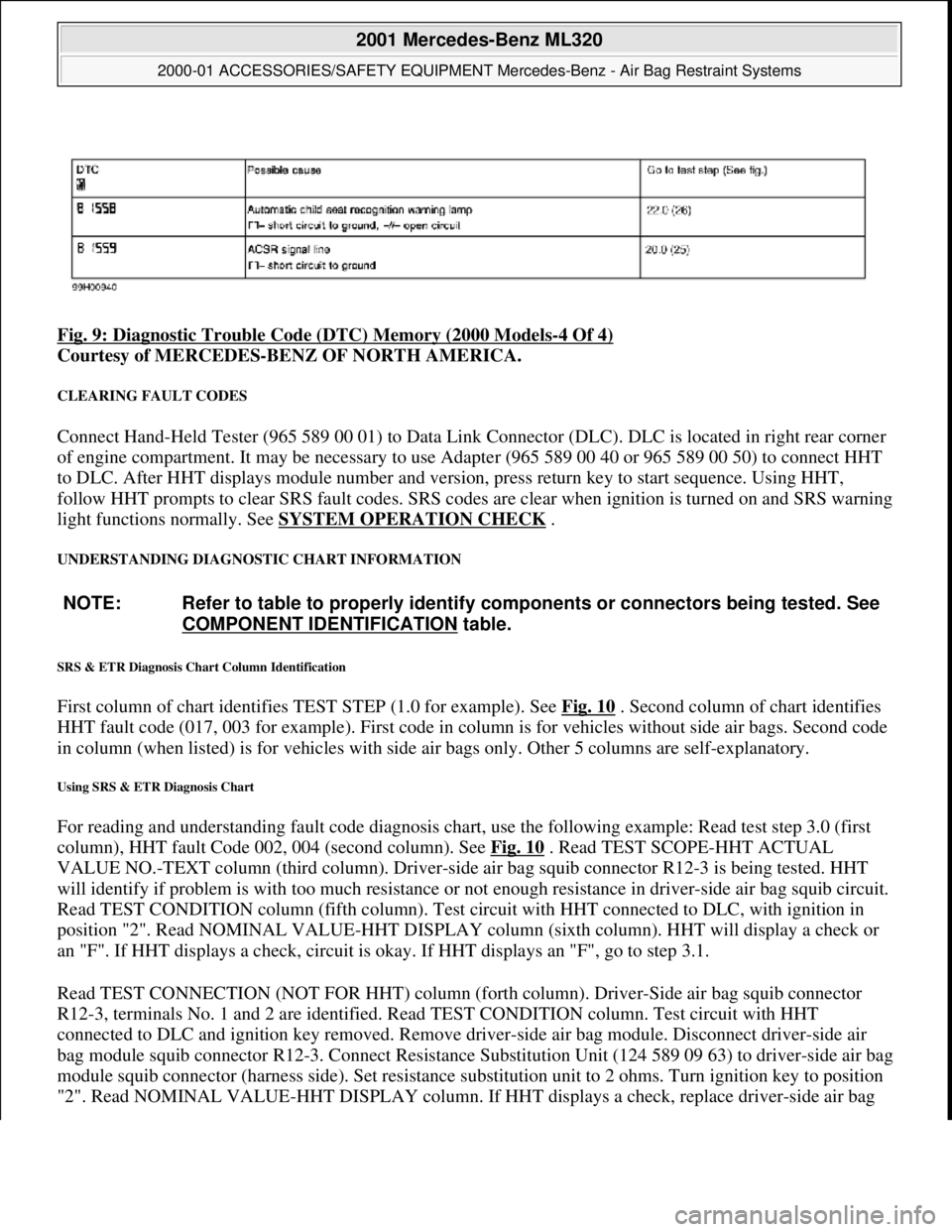
Fig. 9: Diagnostic Trouble Code (DTC) Memory (2000 Models-4 Of 4)
Courtesy of MERCEDES-BENZ OF NORTH AMERICA.
CLEARING FAULT CODES
Connect Hand-Held Tester (965 589 00 01) to Data Link Connector (DLC). DLC is located in right rear corner
of engine compartment. It may be necessary to use Adapter (965 589 00 40 or 965 589 00 50) to connect HHT
to DLC. After HHT displa ys module number and version, press return key to start sequence. Using HHT,
follow HHT prompts to clear SRS faul t codes. SRS codes are clear when ignition is turned on and SRS warning
light functions normally. See SYSTEM OPERATION CHECK
.
UNDERSTANDING DIAGNOSTIC CHART INFORMATION
SRS & ETR Diagnosis Chart Column Identification
First column of chart identifies TEST STEP (1.0 for example). See Fig. 10 . Second column of chart identifies
HHT fault code (017, 003 for example). First code in column is for ve hicles without side air bags. Second code
in column (when listed) is for ve hicles with side air bags only. Ot her 5 columns are self-explanatory.
Using SRS & ETR Diagnosis Chart
For reading and understanding fault code diagnosis chart, use the following example: Read test step 3.0 (first
column), HHT fault Code 002, 004 (second column). See Fig. 10
. Read TEST SCOPE-HHT ACTUAL
VALUE NO.-TEXT column (third column). Driver-side air bag squib connector R12-3 is being tested. HHT
will identify if problem is with too much resistance or not enough resistance in driver-side air bag squib circuit.
Read TEST CONDITION column (fifth column). Test ci rcuit with HHT connected to DLC, with ignition in
position "2". Read NOMINAL VALUE-HHT DISPLAY column (sixth column). HHT will display a check or
an "F". If HHT displays a check, circuit is okay. If HHT displays an "F", go to step 3.1.
Read TEST CONNECTION (NOT FOR HHT) column (fort h column). Driver-Side air bag squib connector
R12-3, terminals No. 1 and 2 are id entified. Read TEST CONDITION column. Test circuit with HHT
connected to DLC and igni tion key removed. Remove driver-side air bag module. Disconnect driver-side air
bag module squib connector R12-3. Conn ect Resistance Substitution Unit (124 589 09 63) to driver-side air bag
module squib connector (harness side). Set resistance substitution unit to 2 ohms. Turn ignition key to position
"2". Read NOMINAL VALUE-HHT DISPLAY column. If HHT displa
ys a check, replace driver-side air bag
NOTE: Refer to table to properly identify components or connectors being tested. See
COMPONENT IDENTIFICATION
table.
2001 Mercedes-Benz ML320
2000-01 ACCESSORIES/SAFETY EQUIPMENT Merc edes-Benz - Air Bag Restraint Systems
me
Saturday, October 02, 2010 3:44:46 PMPage 20 © 2006 Mitchell Repair Information Company, LLC.
Page 385 of 4133
module. If HHT displays an "F", go to step 3.2.
Read TEST CONNECTION (NOT FOR HHT) column. Horn -air bag clockspring connector A45x1, terminals
No. 1 and 2 are identified. Read TEST CONDITION column. Test circuit with HHT connected to DLC.
Remove ignition key. Connect Resist ance Substitution Unit (124 589 09 63 00) to horn-air bag clockspring
connector A45x1. Set resistance s ubstitution unit to 2 ohms. Read NOMINAL VALUE-HHT DISPLAY
column. If HHT displays a check, check horn-air ba g clockspring for continuity. Replace horn-air bag
clockspring as necessary. If HHT displays an "F", go to step 3.4.
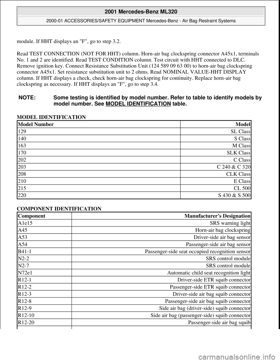
MODEL IDENTIFICATION
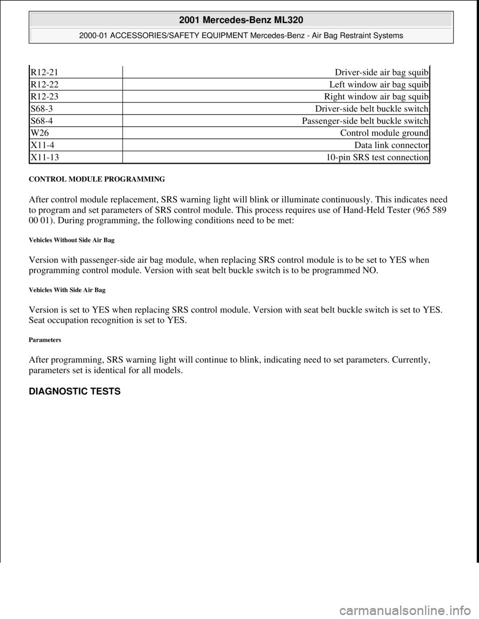
COMPONENT IDENTIFICATION
NOTE: Some testing is identified
by model number. Refer to table to identify models by
model number. See MO DEL IDENTIFICATION
table.
Model NumberModel
129SL Class
140S Class
163M Class
170SLK Class
202C Class
203C 240 & C 320
208CLK Class
210E Class
215CL 500
220S 430 & S 500
ComponentManufacturer's Designation
A1e15SRS warning light
A45Horn-air bag clockspring
A53Driver-side air bag sensor
A54Passenger-side air bag sensor
B41-1Passenger-side seat occupied recognition sensor
N2-2SRS control module
N2-7SRS control module
N72e1Automatic child seat recognition light
R12-1Driver-side ETR squib connector
R12-2Passenger-side ETR squib connector
R12-3Driver-side air bag squib connector
R12-8Passenger-side air bag squib connector
R12-9Side air bag (driver-side) squib connector
R12-10Side air bag (passenge r-side) squib connector
R12-20Passenger-side air bag squib
2001 Mercedes-Benz ML320
2000-01 ACCESSORIES/SAFETY EQUIPMENT Merc edes-Benz - Air Bag Restraint Systems
me
Saturday, October 02, 2010 3:44:46 PMPage 21 © 2006 Mitchell Repair Information Company, LLC.
Page 386 of 4133
CONTROL MODULE PROGRAMMING
After control module replacement, SRS warning light will blink or illuminate continuously. This indicates need
to program and set paramete rs of SRS control module. This process requires use of Hand-Held Tester (965 589
00 01). During programming, the follow ing conditions need to be met:
Vehicles Without Side Air Bag
Version with passenger-side air bag module, when replac ing SRS control module is to be set to YES when
programming control module. Version with seat belt buckle switch is to be programmed NO.
Vehicles With Side Air Bag
Version is set to YES when replacing SRS control module. Version with seat belt buckle switch is set to YES.
Seat occupation recogni tion is set to YES.
Parameters
After programming, SRS warning light wi ll continue to blink, indicating need to set parameters. Currently,
parameters set is identical for all models.
DIAGNOSTIC TESTS
R12-21Driver-side air bag squib
R12-22Left window air bag squib
R12-23Right window air bag squib
S68-3Driver-side belt buckle switch
S68-4Passenger-side belt buckle switch
W26Control module ground
X11-4Data link connector
X11-1310-pin SRS test connection
2001 Mercedes-Benz ML320
2000-01 ACCESSORIES/SAFETY EQUIPMENT Merc edes-Benz - Air Bag Restraint Systems
me
Saturday, October 02, 2010 3:44:46 PMPage 22 © 2006 Mitchell Repair Information Company, LLC.