Page 1841 of 4133
Fig. 255: Identifying Retrofitting Illuminated Door Sill Molding Components
It is also possible to order the illuminated door sill molding with the lettering "AMG" - see parts ordering
notes.
Removal
Contact with components
under high voltage can
pose lethal hazardDo not touch parts which
conduct high voltages.
Persons who wear
electronic implants (e.g.
heart pacemakers) must
not carry out any work on
such components.AS00.00-Z-0020-01A
1Connect quiescent current
retention unit *WH58.30-Z-1012-09A
2Disconnect ground cable
of battery
AR54.10-P-0003A
3Open fuse and relay
module (F1)2 covers. Rear cover is
attached with 5 screws.
4Remove screws for fuse
block 2 screws at front.
5Remove door sill
moldings on right and left Up to VIN A145272,
X708318: Begin in the
2001 Mercedes-Benz ML320
1998-2005 ACCESSORIES & BODY, CAB Electrical System - Body - 163 Chassis
me
Saturday, October 02, 2010 3:30:11 PMPage 346 © 2006 Mitchell Repair Information Company, LLC.
Page 1881 of 4133
Fig. 301: Identifying Video/DVD Player, Striker And Locking Arm
RETROFIT VOLTAGE SUPPLY FOR CENTRAL INTERFACE MODULE - AZ82.60-P-0004-06A
Model 163.136 /154 /172 #A as of 145273, Models 163.136 /154 /172 #X as of 708319, Models
163.113/128 /157 /174 /175
1. Remove cover for fuse unit in right footwell.
Turn arresting mechanisms counterclockwise and move out cover to the rear.
2. Route plug for voltage supply (1) for the interface module of the fuse unit into the glove compartment
opening.
Guide cable under the right-hand instrument panel support (2).
View of left-hand steering installation
2001 Mercedes-Benz ML320
1998-2005 ACCESSORIES & BODY, CAB Electrical System - Body - 163 Chassis
me
Saturday, October 02, 2010 3:30:12 PMPage 386 © 2006 Mitchell Repair Information Company, LLC.
Page 1882 of 4133

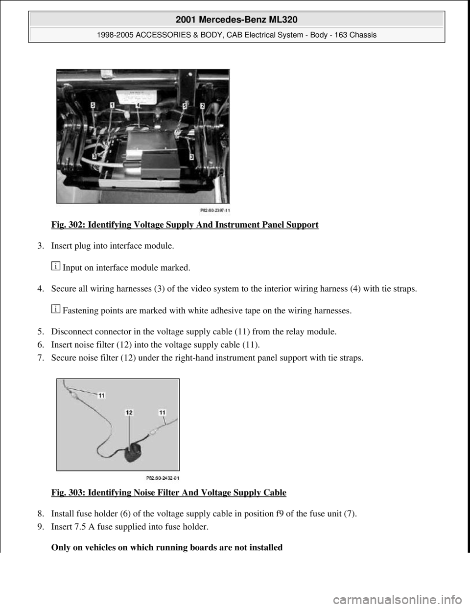
Fig. 302: Identifying Voltage Supply And Instrument Panel Support
3. Insert plug into interface module.
Input on interface module marked.
4. Secure all wiring harnesses (3) of the video system to the interior wiring harness (4) with tie straps.
Fastening points are marked with white adhesive tape on the wiring harnesses.
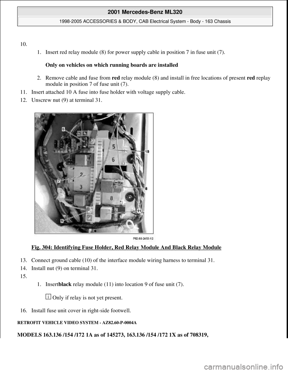
5. Disconnect connector in the voltage supply cable (11) from the relay module.
6. Insert noise filter (12) into the voltage supply cable (11).
7. Secure noise filter (12) under the right-hand instrument panel support with tie straps.
Fig. 303: Identifying Noise Filter And Voltage Supply Cable
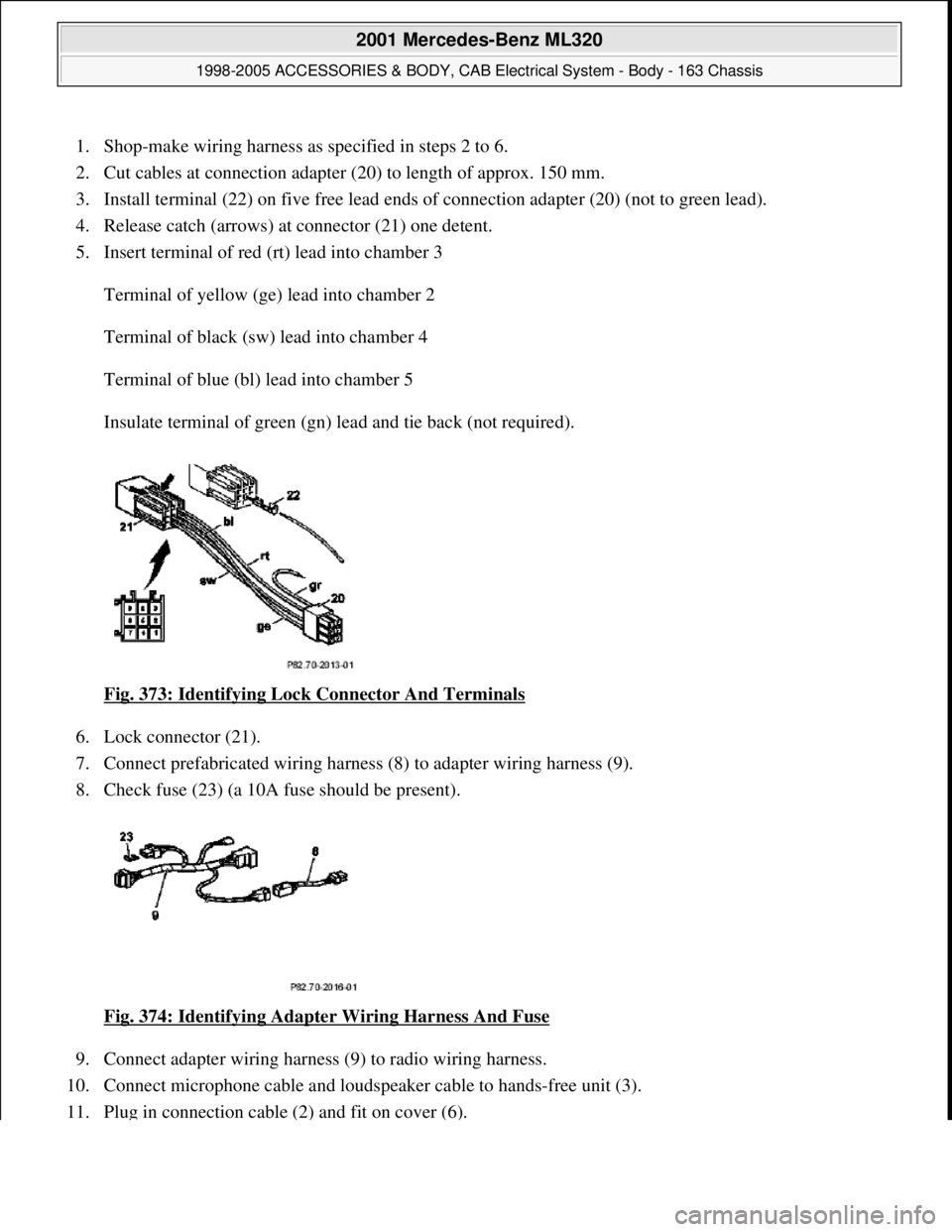
8. Install fuse holder (6) of the voltage supply cable in position f9 of the fuse unit (7).
9. Insert 7.5 A fuse supplied into fuse holder.
Only on vehicles on which running boards are not installed
2001 Mercedes-Benz ML320
1998-2005 ACCESSORIES & BODY, CAB Electrical System - Body - 163 Chassis
me
Saturday, October 02, 2010 3:30:12 PMPage 387 © 2006 Mitchell Repair Information Company, LLC.
Page 1883 of 4133

10.
1. Insert red relay module (8) for power supply cable in position 7 in fuse unit (7).
Only on vehicles on which running boards are installed
2. Remove cable and fuse from red relay module (8) and install in free locations of present redreplay
module in position 7 of fuse unit (7).
11. Insert attached 10 A fuse into fuse holder with voltage supply cable.
12. Unscrew nut (9) at terminal 31.
Fig. 304: Identifying Fuse Holder, Red Relay Module And Black Relay Module
13. Connect ground cable (10) of the interface module wiring harness to terminal 31.
14. Install nut (9) on terminal 31.
15.
1. Insertblack relay module (11) into location 9 of fuse unit (7).
Only if relay is not yet present.
16. Install fuse unit cover in right-side footwell.
RETROFIT VEHICLE VIDEO SYSTEM - AZ82.60-P-0004A
MODELS 163.136 /154 /172 1A as of 145273, 163.136 /154 /172 1X as of 708319,
2001 Mercedes-Benz ML320
1998-2005 ACCESSORIES & BODY, CAB Electrical System - Body - 163 Chassis
me
Saturday, October 02, 2010 3:30:12 PMPage 388 © 2006 Mitchell Repair Information Company, LLC.
Page 1911 of 4133
Fig. 344: Identifying CAN Bus Adapter
11. Install white (ws) and blue (bl) fuse on connector for transfer case control module (N78) from CAN bus
wiring harness (9) as shown in figure.
Fig. 345: Identifying Transfer Case Cont rol Module And CAN Bus Wiring Harness
12. Disconnect connector from transfer case control module (N78) and connect CAN bus wiring harness (9)
between transfer case control module (N78) and standard wiring harness.
Illustrated without center console
13. Connect CAN connector (6) from CAN bus wiring harnes s (9) to CAN bus adapter (5).
Fig. 346: Identifying CAN Bu s Adapter And CAN Connector
2001 Mercedes-Benz ML320
1998-2005 ACCESSORIES & BODY, CAB Electr ical System - Body - 163 Chassis
me
Saturday, October 02, 2010 3:30:13 PMPage 416 © 2006 Mitchell Repair Information Company, LLC.
Page 1924 of 4133
Fig. 368: Identifying Lock Connector And Cable Terminals
12. Insert wiring harness (2) into instrument panel working from the glove compartment.
The tied-back part must be placed below the strut (arrows) at the glove compartment.
Fig. 369: Identifying Telephone Wiring Harness
13. Connect telephone wiring harness (2) to adapter wiring harness (9).
14. Check fuse (23) (a 10A fuse should be present).
2001 Mercedes-Benz ML320
1998-2005 ACCESSORIES & BODY, CAB Electrical System - Body - 163 Chassis
me
Saturday, October 02, 2010 3:30:13 PMPage 429 © 2006 Mitchell Repair Information Company, LLC.
Page 1925 of 4133
Fig. 370: Identifying Fuse A nd Telephone Wiring Harness
15. Connect adapter wiring harness (9) to radio wiring harness and insert into radio slot.
16. Place microphone cable of telephone wi ring harness (2) into radio slot.
Fig. 371: Identifying Adapter Wiring Ha rness And Telephone Wiring Harness
17. Route connection cable of telephone wiring harness (2) to telephone handset in middle tunnel as shown in
figure.
Fig. 372: Identifying Telephone Wiring Harness
RETROFIT WIRING HARN ESS - AZ82.70-P-0001-04D
Model 163 as of 1.12.99 up to 31.8.00 for Nokia 3110 portable CTEL
2001 Mercedes-Benz ML320
1998-2005 ACCESSORIES & BODY, CAB Electr ical System - Body - 163 Chassis
me
Saturday, October 02, 2010 3:30:13 PMPage 430 © 2006 Mitchell Repair Information Company, LLC.
Page 1926 of 4133

1. Shop-make wiring harness as specified in steps 2 to 6.
2. Cut cables at connection adapter (20) to length of approx. 150 mm.
3. Install terminal (22) on five fr ee lead ends of connection adapter (20) (not to green lead).
4. Release catch (arrows) at connector (21) one detent.
5. Insert terminal of red (rt) lead into chamber 3
Terminal of yellow (ge) lead into chamber 2
Terminal of black (sw) lead into chamber 4
Terminal of blue (bl) lead into chamber 5
Insulate terminal of green (gn) lead and tie back (not required).
Fig. 373: Identifying Lock Connector And Terminals
6. Lock connector (21).
7. Connect prefabricated wiring harness (8) to adapter wiring harness (9).
8. Check fuse (23) (a 10A fuse should be present).
Fig. 374: Identifying Adapter Wiring Harness And Fuse
9. Connect adapter wiring harness (9) to radio wiring harness.
10. Connect microphone cable and loudspeaker cable to hands-free unit (3).
11. Plu
g in connection cable (2) and fit on cover (6).
2001 Mercedes-Benz ML320
1998-2005 ACCESSORIES & BODY, CAB Electr ical System - Body - 163 Chassis
me
Saturday, October 02, 2010 3:30:13 PMPage 431 © 2006 Mitchell Repair Information Company, LLC.