1997 MERCEDES-BENZ ML350 ECO mode
[x] Cancel search: ECO modePage 239 of 4133
189 Driving instructions
Te ch n ica l
data Instruments
and controlsOperationDrivingInstrument
cluster displayPractical hints Car care Index Returning from off-road driving
Off-road driving increases strain on the vehicle.
We recommend that you inspect the vehicle for possible
damage after each off-road trip. Recognizing any
damage and a subsequent timely repair reduces the
chance of a possible breakdown or accident later on.
Proceed as follows:
•Switch off the LOW RANGE mode, see page 209.
•Remove excessive dirt from tires, wheels, wheel
housings, and underbody. For instance, after driving
in mud, clean the radiator, chassis, engine, brakes,
and wheels from extreme dirt, using a strong jet of
water.
•Inspect frame, oil pan, brake hoses, etc., as well as
vehicle underbody for possible damage.
•Check tires for possible damage, clean all exterior
lamps, and conduct a brake test.•Check for brush or branches caught in the
undercarriage. They could increase the possibility of
a fire, as well as cut fuel and / or brake lines,
puncture rubber bellows of the axles or drive shafts.
Wa r n i n g !
If you feel a sudden significant vibration or ride
disturbance, or you suspect that possible damage to
your vehicle has occurred, you should turn on the
hazard warning flashers, carefully slow down, and
drive with caution to an area which is a safe
distance from the roadway.Inspect the tires and under the vehicle for possible
damage. If the vehicle or tires appear unsafe, have
it towed to the nearest Mercedes-Benz Light Truck
Center or tire dealer for repairs.
Page 254 of 4133
204 Driving systems
Te ch n ica l
data Instruments
and controlsOperationDrivingInstrument
cluster displayPractical hints Car care Index
Note:
In winter operation, the maximum effectiveness of the
electronic traction system is only achieved with
Mercedes-Benz recommended M+S rated radial-ply tires
and / or snow chains.
LOW RANGE – 4-ETS+
During off-road driving a special low range system for
the four wheel electronic traction system (4-ETS+) is
operational with transmission in LOW RANGE mode,
see page 211.
If one or more tires lose traction while driving downhill
(accelerator released), the 4-ETS+ engages and the
warning lampv, located in the speedometer dial,
starts to f lash.Electronic brake proportioning (EBP)
The EBP enhances braking effectiveness by allowing the
rear brakes to supply a greater proportion of the braking
effort without a loss of vehicle stability.
If a warning tone sounds for five seconds and the
symbols É and - are displayed in the instrument
cluster, the system has detected a malfunction and is
switched off. Have the system checked immediately at
an authorized Mercedes-Benz Light Truck Center.
Failure to do so could result in an accident, since the
enhanced braking effect is not available when the
system is switched off.
Note:
When the EBP is switched off, every time the engine is
started, a warning tone will sound for five seconds and
the symbols É and - will light up. In addition,
whenever the brakes are applied at speeds exceeding
25 mph (40 km / h), the warning tone sounds for five
seconds.
Page 290 of 4133

240 Tires, Wheels
Te ch n ica l
data Instruments
and controlsOperation DrivingInstrument
cluster displayPractical hintsCar care Index
Wheels
Replace rims or tires with the same designation,
manufacturer and type as shown on the original part.
See your authorized Mercedes-Benz Light Truck Center
for further information.
See your authorized Mercedes-Benz Light Truck Center
for information on tested and recommended rims and
tires for summer and winter operation. They can also
offer advice concerning tire service and purchase.Tire replacement
Front and rear tires should be replaced in sets.
Furthermore – in the event of tire replacement – the
optional regular size spare wheel should be used on the
rear axle. Rims and tires must be of the correct size and
type. For dimensions, see technical data on page 288.
We recommend that you break in new tires for
approximately 60 miles (100 km) at moderate speed.
It is imperative that the wheel mounting bolts be
fastened to a tightening torq ue of 110 ft.lb. (150 Nm)
whenever wheels are mounted.
For rim and tire specifications, refer to technical data on
page 288.
Wa r n i n g !
Do not mix different tire construction types (i.e.
radial, bias, bias-belted) on your vehicle because
handling may be adversely affected and may result
in loss of control.
Wa r n i n g !
Worn, old tires can cause accidents. If the tire tread
is badly worn, or if the tires have sustained
damage, replace them.When replacing rims, use only genuine
Mercedes-Benz wheel bolts specified for the
particular rim type. Failure to do so can result in
the bolts loosening and possibly an accident.
Page 322 of 4133
272 Emergency operation of sliding/pop-up roof
Te ch n ica l
data Instruments
and controlsOperation DrivingInstrument
cluster displayPractical hintsCar care Index
Emergency operation of sliding/pop-up roof
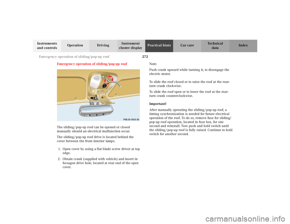
The sliding / pop-up roof can be opened or closed
manually should an electrical malfunction occur.
The sliding / pop-up roof drive is located behind the
cover between the front interior lamps.
1. Open cover by using a f lat blade screw driver at top
edge.
2. Obtain crank (supplied with vehicle) and insert in
hexagon drive hole, located at rear end of the open
cover.Note:
Push crank upward while turning it, to disengage the
electric motor.
To slide the roof closed or to raise the roof at the rear:
turn crank clockwise.
To slide the roof open or to lower the roof at the rear:
turn crank counterclockwise.
Important!
After manually operating the sliding / pop-up roof, a
timing synchronization is needed for future electrical
operation of the roof. To do so, remove fuse for sliding/
pop-up roof operation, located in fuse box, for one
second and reinstall. Now push and hold switch until
the sliding / pop-up roof is fully raised. Continue to hold
switch for another second.
RESETMODEMODE
Page 342 of 4133
292 Fuels, coolants, lubricants etc. - capacities
Te ch n ica l
data Instruments
and controlsOperation DrivingInstrument
cluster displayPractical hints Car care Index
Fuels, coolants, lubricants etc. – capacities
Vehicle components and their respective lubricants must match. Therefore use only brands tested and recommended
by us. Please refer to the Factory Approved Service Products pamphlet, or inquire at your Mercedes-Benz Light Truck
Center.
Fuels, coolants, lubricants etc. Model Capacity
Engine with oil filter
(recommended engine oils)ML 320 / ML 430
ML 55 AMG8.5 US qt (8.0 l)
8.0 US qt (7.5 l)
Automatic transmission
(automatic transmission fluid)9.0 US qt (8.5 l)
Transfer case
(Dexron 3 or Dexron 2E)1. 6 U S q t (1. 5 l )
Rear axle
(Hypoid gear oil SAE 90, 85 W 90)1.3 US qt (1.25 l)
Front axle
(Hypoid gear oil SAE 90)1. 2 U S q t (1. 1 l )
Power steering
(MB Power steering fluid)approx. 0.65 US qt (0.6 l)
Front wheel hubs
(high temperature roller bearing grease)approx. 1.5 oz (43 g) each
Page 365 of 4133
2000-01 ACCESSORIES/SA FETY EQUIPMENT
Mercedes-Benz - Air Bag Restraint Systems
DESCRIPTION & OPERATION
All models are equipped with Supplemental Restraint Syst em (SRS). The main components of SRS are driver-
side air bag module, passenger-side air bag module, si de air bag modules (located in doors), SRS control
module, side air bag sensors, SRS warning light, driver knee bolster, pa ssenger knee bolster, and Emergency
Tensioning Retractor (ETR) seat belt assembly. Additionally, some vehicles may be equipped with head impact
(curtain type) air bags (located ar ound door windows behind door frame trims).
Both SRS and ETR are electronically activated by a single control module. There are 2 thresholds which must
be exceeded to trigger an ETR acti on, air bag deployment, or both. If a moderately severe frontal collision
occurs exceeding first triggering thre shold where protection from safety belt is sufficient, only Emergency
Tensioning Retractor (ETR) is activated if safety belt is buckled. If a moderately severe frontal collision occurs
exceeding first triggering threshold where protection from safety belt is sufficient, but safety belt is not buckled,
air bag is deployed and ETR is not activated.
If a severe frontal collision occurs exceeding second triggering threshold where protection from safety belt is
insufficient, air bag is deploye d. ETR is activated if safety belt is buckled. If safety belt is not buckled, ETR is
not activated when second triggering threshold is reached. Passenger air bag will deploy even if passenger seat
is not occupied when a triggering thre shold is exceeded. If during a severe frontal collision the power supply is
interrupted, the driver and passenger air bag can still be deployed, but ETR cannot be activated.
The side air bag on the driver-side deploys whenever th e driver-side air bag module is deployed and when there
is a substantial side impact crash. The air bag on the pa ssenger-side will activate only when a sensor (Occupied
Seat Recognition Sensor) in the passenger seat sends a si gnal to the SRS control module that the passenger-side
seat is occupied. During a collision, the side air bag will then deploy.
COMPONENT LOCATIONS NOTE: The following 2000 in
formation represents the latest information available at
time of publication and m ay be useful in diagnosing 2001 vehicles. 2001 wiring
diagrams have been included at the end of this article.
WARNING: Accidental air bag deployment is pos sible. Personal injury may result.
Read and follow all WARNINGS and AIR BAG SAFETY PRECAUTIONS
before working on ai r bag system or related components.
2001 Mercedes-Benz ML320
2000-01 ACCESSORIES/SAFETY EQUIPMENT Merc edes-Benz - Air Bag Restraint Systems
2001 Mercedes-Benz ML320
2000-01 ACCESSORIES/SAFETY EQUIPMENT Mercedes-Benz - Air Bag Restraint Systems
me
Saturday, October 02, 2010 3:44:44 PMPage 1 © 2006 Mitchell Repair Information Company, LLC.
me
Saturday, October 02, 2010 3:44:49 PMPage 1 © 2006 Mitchell Repair Information Company, LLC.
Page 377 of 4133

Fig. 4: Removing Occupied Seat Recognition Sensor (2000 Models)
Courtesy of MERCEDES-BENZ OF NORTH AMERICA.
PASSENGER-SIDE AIR BAG MODULE
Removal & Installation (C Class)
1. Before proceeding, See AIR BAG SAFETY PRECAUTIONS . Disable air bag system. See
DISABLING & ACTIVATI NG AIR BAG SYSTEM
. Remove ignition key. Remove instrument panel.
2001 Mercedes-Benz ML320
2000-01 ACCESSORIES/SAFETY EQUIPMENT Merc edes-Benz - Air Bag Restraint Systems
me
Saturday, October 02, 2010 3:44:45 PMPage 13 © 2006 Mitchell Repair Information Company, LLC.
Page 384 of 4133

Fig. 9: Diagnostic Trouble Code (DTC) Memory (2000 Models-4 Of 4)
Courtesy of MERCEDES-BENZ OF NORTH AMERICA.
CLEARING FAULT CODES
Connect Hand-Held Tester (965 589 00 01) to Data Link Connector (DLC). DLC is located in right rear corner
of engine compartment. It may be necessary to use Adapter (965 589 00 40 or 965 589 00 50) to connect HHT
to DLC. After HHT displa ys module number and version, press return key to start sequence. Using HHT,
follow HHT prompts to clear SRS faul t codes. SRS codes are clear when ignition is turned on and SRS warning
light functions normally. See SYSTEM OPERATION CHECK
.
UNDERSTANDING DIAGNOSTIC CHART INFORMATION
SRS & ETR Diagnosis Chart Column Identification
First column of chart identifies TEST STEP (1.0 for example). See Fig. 10 . Second column of chart identifies
HHT fault code (017, 003 for example). First code in column is for ve hicles without side air bags. Second code
in column (when listed) is for ve hicles with side air bags only. Ot her 5 columns are self-explanatory.
Using SRS & ETR Diagnosis Chart
For reading and understanding fault code diagnosis chart, use the following example: Read test step 3.0 (first
column), HHT fault Code 002, 004 (second column). See Fig. 10
. Read TEST SCOPE-HHT ACTUAL
VALUE NO.-TEXT column (third column). Driver-side air bag squib connector R12-3 is being tested. HHT
will identify if problem is with too much resistance or not enough resistance in driver-side air bag squib circuit.
Read TEST CONDITION column (fifth column). Test ci rcuit with HHT connected to DLC, with ignition in
position "2". Read NOMINAL VALUE-HHT DISPLAY column (sixth column). HHT will display a check or
an "F". If HHT displays a check, circuit is okay. If HHT displays an "F", go to step 3.1.
Read TEST CONNECTION (NOT FOR HHT) column (fort h column). Driver-Side air bag squib connector
R12-3, terminals No. 1 and 2 are id entified. Read TEST CONDITION column. Test circuit with HHT
connected to DLC and igni tion key removed. Remove driver-side air bag module. Disconnect driver-side air
bag module squib connector R12-3. Conn ect Resistance Substitution Unit (124 589 09 63) to driver-side air bag
module squib connector (harness side). Set resistance substitution unit to 2 ohms. Turn ignition key to position
"2". Read NOMINAL VALUE-HHT DISPLAY column. If HHT displa
ys a check, replace driver-side air bag
NOTE: Refer to table to properly identify components or connectors being tested. See
COMPONENT IDENTIFICATION
table.
2001 Mercedes-Benz ML320
2000-01 ACCESSORIES/SAFETY EQUIPMENT Merc edes-Benz - Air Bag Restraint Systems
me
Saturday, October 02, 2010 3:44:46 PMPage 20 © 2006 Mitchell Repair Information Company, LLC.