1997 MERCEDES-BENZ ML350 brake sensor
[x] Cancel search: brake sensorPage 2144 of 4133
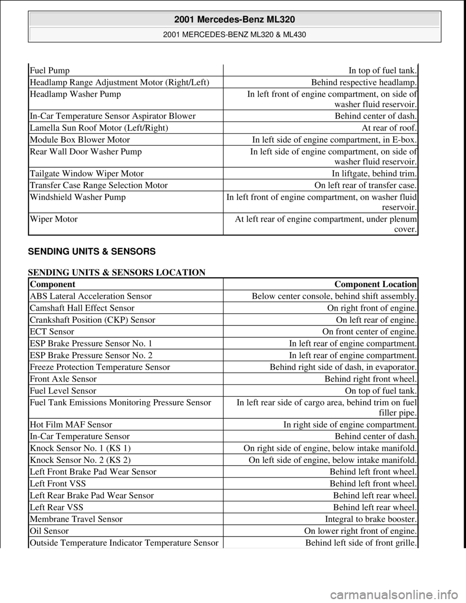
SENDING UNITS & SENSORS
SENDING UNITS & SENSORS LOCATION
Fuel PumpIn top of fuel tank.
Headlamp Range Adjustment Motor (Right/Left)Behind respective headlamp.
Headlamp Washer PumpIn left front of engine compartment, on side of
washer fluid reservoir.
In-Car Temperature Sensor Aspirator BlowerBehind center of dash.
Lamella Sun Roof Motor (Left/Right)At rear of roof.
Module Box Blower MotorIn left side of engine compartment, in E-box.
Rear Wall Door Washer PumpIn left side of engine compartment, on side of
washer fluid reservoir.
Tailgate Window Wiper MotorIn liftgate, behind trim.
Transfer Case Range Selection MotorOn left rear of transfer case.
Windshield Washer PumpIn left front of engine compartment, on washer fluid
reservoir.
Wiper MotorAt left rear of engine compartment, under plenum
cover.
ComponentComponent Location
ABS Lateral Acceleration SensorBelow center console, behind shift assembly.
Camshaft Hall Effect SensorOn right front of engine.
Crankshaft Position (CKP) SensorOn left rear of engine.
ECT SensorOn front center of engine.
ESP Brake Pressure Sensor No. 1In left rear of engine compartment.
ESP Brake Pressure Sensor No. 2In left rear of engine compartment.
Freeze Protection Temperature SensorBehind right side of dash, in evaporator.
Front Axle SensorBehind right front wheel.
Fuel Level SensorOn top of fuel tank.
Fuel Tank Emissions Monitoring Pressure SensorIn left rear side of cargo area, behind trim on fuel
filler pipe.
Hot Film MAF SensorIn right side of engine compartment.
In-Car Temperature SensorBehind center of dash.
Knock Sensor No. 1 (KS 1)On right side of engine, below intake manifold.
Knock Sensor No. 2 (KS 2)On left side of engine, below intake manifold.
Left Front Brake Pad Wear SensorBehind left front wheel.
Left Front VSSBehind left front wheel.
Left Rear Brake Pad Wear SensorBehind left rear wheel.
Left Rear VSSBehind left rear wheel.
Membrane Travel SensorIntegral to brake booster.
Oil SensorOn lower right front of engine.
Outside Temperature Indicator Temperature SensorBehind left side of front grille.
2001 Mercedes-Benz ML320
2001 MERCEDES-BENZ ML320 & ML430
me
Saturday, October 02, 2010 3:21:17 PMPage 4 © 2006 Mitchell Repair Information Company, LLC.
Page 2145 of 4133
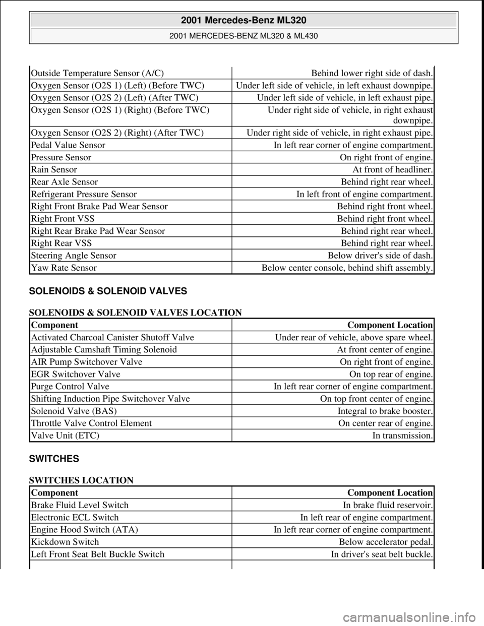
SOLENOIDS & SOLENOID VALVES
SOLENOIDS & SOLENOID VALVES LOCATION
SWITCHES
SWITCHES LOCATION
Outside Temperature Sensor (A/C)Behind lower right side of dash.
Oxygen Sensor (O2S 1) (Left) (Before TWC)Under left side of vehicle, in left exhaust downpipe.
Oxygen Sensor (O2S 2) (Left) (After TWC)Under left side of vehicle, in left exhaust pipe.
Oxygen Sensor (O2S 1) (Right) (Before TWC)Under right side of vehicle, in right exhaust
downpipe.
Oxygen Sensor (O2S 2) (Right) (After TWC)Under right side of vehicle, in right exhaust pipe.
Pedal Value SensorIn left rear corner of engine compartment.
Pressure SensorOn right front of engine.
Rain SensorAt front of headliner.
Rear Axle SensorBehind right rear wheel.
Refrigerant Pressure SensorIn left front of engine compartment.
Right Front Brake Pad Wear SensorBehind right front wheel.
Right Front VSSBehind right front wheel.
Right Rear Brake Pad Wear SensorBehind right rear wheel.
Right Rear VSSBehind right rear wheel.
Steering Angle SensorBelow driver's side of dash.
Yaw Rate SensorBelow center console, behind shift assembly.
ComponentComponent Location
Activated Charcoal Canister Shutoff ValveUnder rear of vehicle, above spare wheel.
Adjustable Camshaft Timing SolenoidAt front center of engine.
AIR Pump Switchover ValveOn right front of engine.
EGR Switchover ValveOn top rear of engine.
Purge Control ValveIn left rear corner of engine compartment.
Shifting Induction Pipe Switchover ValveOn top front center of engine.
Solenoid Valve (BAS)Integral to brake booster.
Throttle Valve Control ElementOn center rear of engine.
Valve Unit (ETC)In transmission.
ComponentComponent Location
Brake Fluid Level SwitchIn brake fluid reservoir.
Electronic ECL SwitchIn left rear of engine compartment.
Engine Hood Switch (ATA)In left rear corner of engine compartment.
Kickdown SwitchBelow accelerator pedal.
Left Front Seat Belt Buckle SwitchIn driver's seat belt buckle.
2001 Mercedes-Benz ML320
2001 MERCEDES-BENZ ML320 & ML430
me
Saturday, October 02, 2010 3:21:17 PMPage 5 © 2006 Mitchell Repair Information Company, LLC.
Page 2149 of 4133
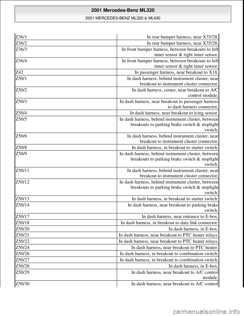
Z36/1In rear bumper harness, near X35/28.
Z36/2In rear bumper harness, near X35/28.
Z36/3In front bumper harness, between breakouts to left
inner sensor & right inner sensor.
Z36/4In front bumper harness, between breakouts to left
inner sensor & right inner sensor.
Z42In passenger harness, near breakout to X18.
Z50/1In dash harness, behind instrument cluster, near
breakout to instrument cluster connector.
Z50/2In dash harness, center, near breakout to A/C
control module.
Z50/3In dash harness, near breakout to passenger harness
to dash harness connector.
Z50/4In dash harness, near breakout to icing sensor.
Z50/5In dash harness, behind instrument cluster, between
breakouts to parking brake switch & stoplight
switch.
Z50/6In dash harness, behind instrument cluster, near
breakout to instrument cluster connector.
Z50/8In dash harness, in breakout to starter switch.
Z50/9In dash harness, behind instrument cluster, between
breakouts to parking brake switch & stoplight
switch.
Z50/11In dash harness, behind instrument cluster, near
breakout to instrument cluster connector.
Z50/12In dash harness, behind instrument cluster, between
breakouts to parking brake switch & stoplight
switch.
Z50/13In dash harness, in breakout to starter switch.
Z50/14In dash harness, near breakout to parking brake
switch.
Z50/17In dash harness, near entrance to E-box.
Z50/18In dash harness, in breakout to data link connector.
Z50/20In dash harness, in E-box.
Z50/21In dash harness, near breakout to PTC heater relays.
Z50/22In dash harness, near breakout to PTC heater relays.
Z50/24In dash harness, near breakout to PTC heater.
Z50/26In dash harness, in breakout to combination switch.
Z50/27In dash harness, in breakout to combination switch.
Z50/28In dash harness, in E-box.
Z50/29In dash harness, near breakout to A/C control
module.
Z50/30In dash harness, near breakout to A/C control
2001 Mercedes-Benz ML320
2001 MERCEDES-BENZ ML320 & ML430
me
Saturday, October 02, 2010 3:21:17 PMPage 9 © 2006 Mitchell Repair Information Company, LLC.
Page 2150 of 4133
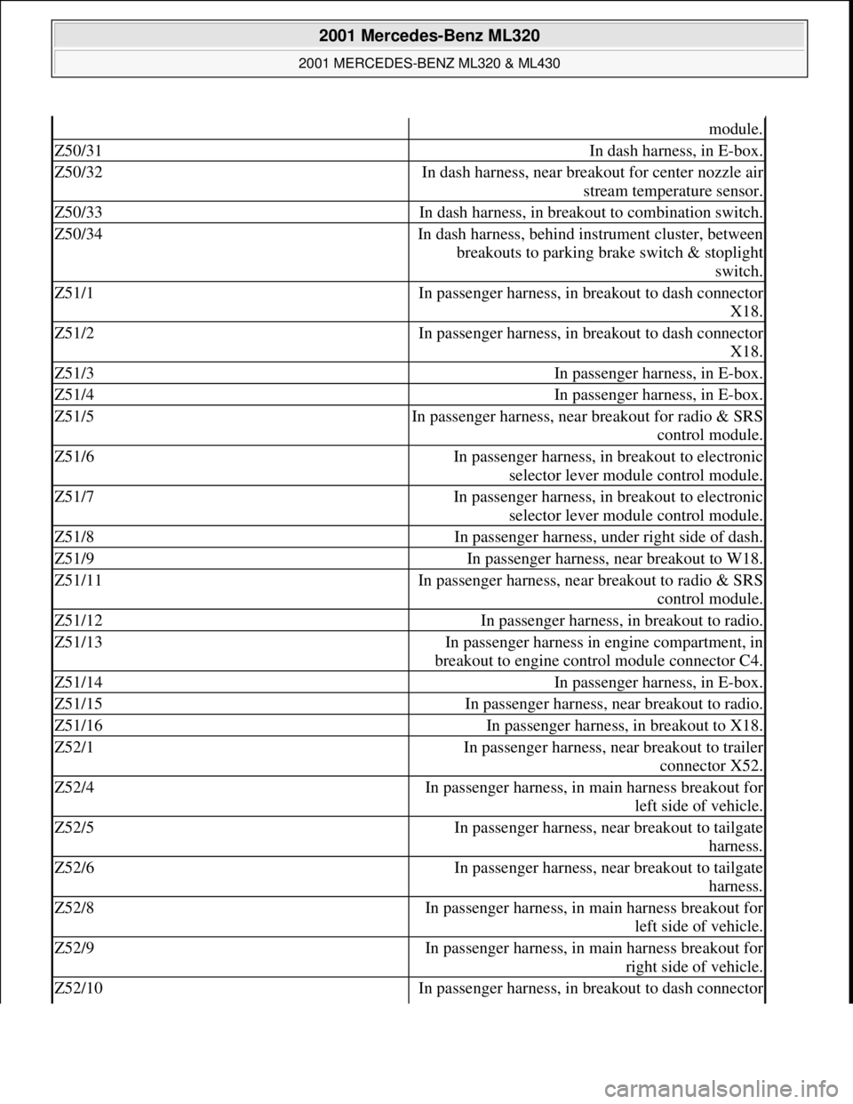
module.
Z50/31In dash harness, in E-box.
Z50/32In dash harness, near breakout for center nozzle air
stream temperature sensor.
Z50/33In dash harness, in breakout to combination switch.
Z50/34In dash harness, behind instrument cluster, between
breakouts to parking brake switch & stoplight
switch.
Z51/1In passenger harness, in breakout to dash connector
X18.
Z51/2In passenger harness, in breakout to dash connector
X18.
Z51/3In passenger harness, in E-box.
Z51/4In passenger harness, in E-box.
Z51/5In passenger harness, near breakout for radio & SRS
control module.
Z51/6In passenger harness, in breakout to electronic
selector lever module control module.
Z51/7In passenger harness, in breakout to electronic
selector lever module control module.
Z51/8In passenger harness, under right side of dash.
Z51/9In passenger harness, near breakout to W18.
Z51/11In passenger harness, near breakout to radio & SRS
control module.
Z51/12In passenger harness, in breakout to radio.
Z51/13In passenger harness in engine compartment, in
breakout to engine control module connector C4.
Z51/14In passenger harness, in E-box.
Z51/15In passenger harness, near breakout to radio.
Z51/16In passenger harness, in breakout to X18.
Z52/1In passenger harness, near breakout to trailer
connector X52.
Z52/4In passenger harness, in main harness breakout for
left side of vehicle.
Z52/5In passenger harness, near breakout to tailgate
harness.
Z52/6In passenger harness, near breakout to tailgate
harness.
Z52/8In passenger harness, in main harness breakout for
left side of vehicle.
Z52/9In passenger harness, in main harness breakout for
right side of vehicle.
Z52/10In passenger harness, in breakout to dash connector
2001 Mercedes-Benz ML320
2001 MERCEDES-BENZ ML320 & ML430
me
Saturday, October 02, 2010 3:21:17 PMPage 10 © 2006 Mitchell Repair Information Company, LLC.
Page 2523 of 4133
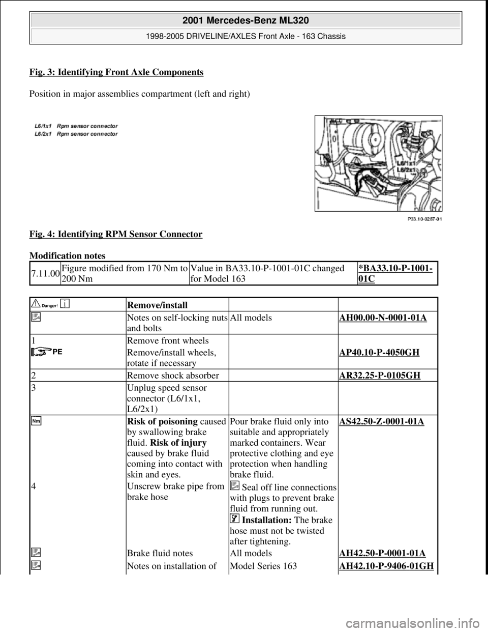
Fig. 3: Identifying Front Axle Components
Position in major assemblies compartment (left and right)
Fig. 4: Identifying RPM Sensor Connector
Modification notes
7.11.00Figure modified from 170 Nm to
200 NmValue in BA33.10-P-1001-01C changed
for Model 163*BA33.10-P-1001-
01C
Remove/install
Notes on self-locking nuts
and boltsAll modelsAH00.00-N-0001-01A
1Remove front wheels
Remove/install wheels,
rotate if necessaryAP40.10-P-4050GH
2Remove shock absorber AR32.25-P-0105GH
3Unplug speed sensor
connector (L6/1x1,
L6/2x1)
Risk of poisoning caused
by swallowing brake
fluid. Risk of injury
caused by brake fluid
coming into contact with
skin and eyes.Pour brake fluid only into
suitable and appropriately
marked containers. Wear
protective clothing and eye
protection when handling
brake fluid.AS42.50-Z-0001-01A
4Unscrew brake pipe from
brake hoseSeal off line connections
with plugs to prevent brake
fluid from running out.
Installation: The brake
hose must not be twisted
after tightening.
Brake fluid notesAll modelsAH42.50-P-0001-01A
Notes on installation of Model Series 163AH42.10-P-9406-01GH
2001 Mercedes-Benz ML320
1998-2005 DRIVELINE/AXLES Front Axle - 163 Chassis
me
Saturday, October 02, 2010 3:38:21 PMPage 4 © 2006 Mitchell Repair Information Company, LLC.
Page 2532 of 4133
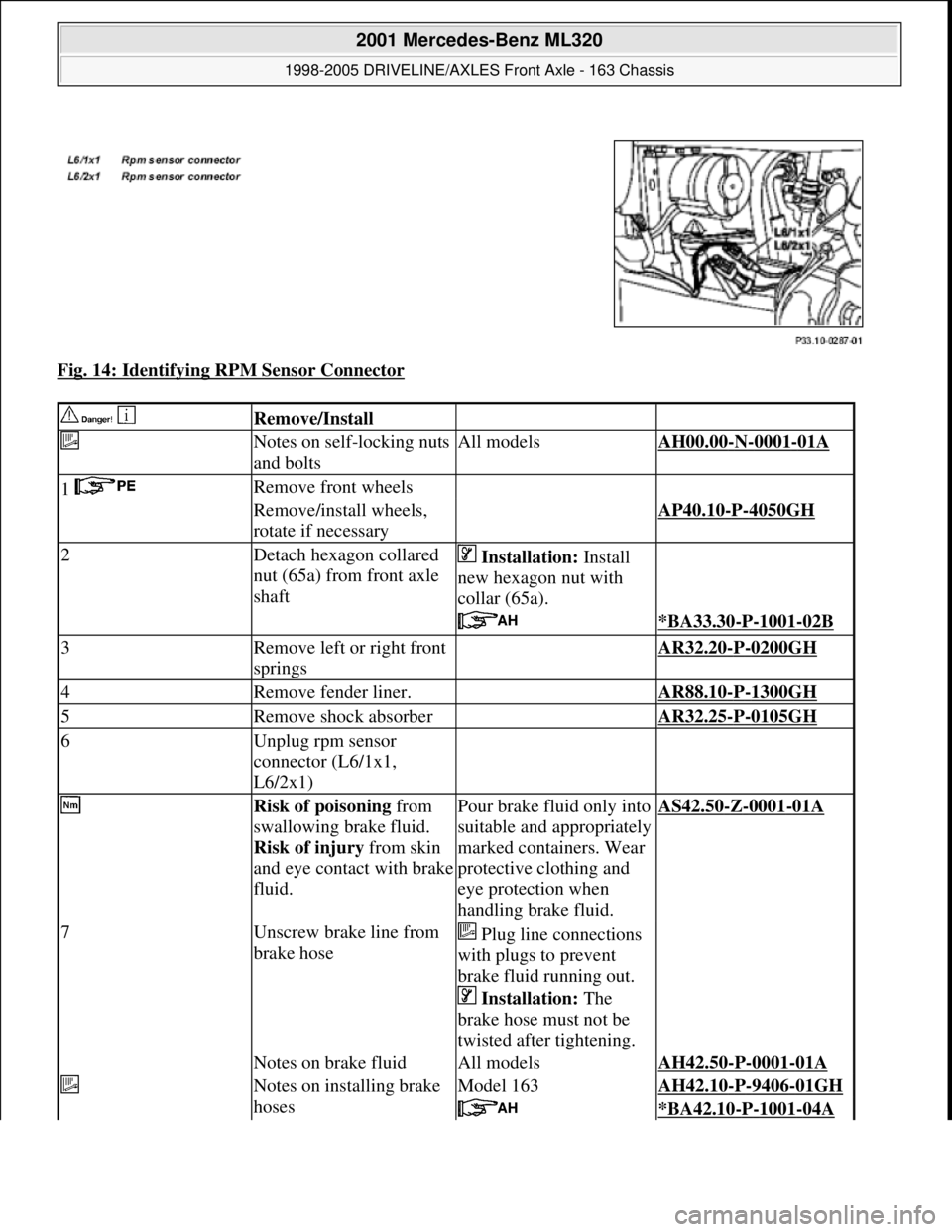
Fig. 14: Identifying RPM Sensor Connector
Remove/Install
Notes on self-locking nuts
and boltsAll modelsAH00.00-N-0001-01A
1 Remove front wheels
Remove/install wheels,
rotate if necessaryAP40.10-P-4050GH
2Detach hexagon collared
nut (65a) from front axle
shaft Installation: Install
new hexagon nut with
collar (65a).
*BA33.30-P-1001-02B
3Remove left or right front
springs AR32.20-P-0200GH
4Remove fender liner. AR88.10-P-1300GH
5Remove shock absorber AR32.25-P-0105GH
6Unplug rpm sensor
connector (L6/1x1,
L6/2x1)
Risk of poisoning from
swallowing brake fluid.
Risk of injury from skin
and eye contact with brake
fluid.Pour brake fluid only into
suitable and appropriately
marked containers. Wear
protective clothing and
eye protection when
handling brake fluid.AS42.50-Z-0001-01A
7Unscrew brake line from
brake hose Plug line connections
with plugs to prevent
brake fluid running out.
Installation: The
brake hose must not be
twisted after tightening.
Notes on brake fluidAll modelsAH42.50-P-0001-01A
Notes on installing brake
hosesModel 163AH42.10-P-9406-01GH
*BA42.10-P-1001-04A
2001 Mercedes-Benz ML320
1998-2005 DRIVELINE/AXLES Front Axle - 163 Chassis
me
Saturday, October 02, 2010 3:38:22 PMPage 13 © 2006 Mitchell Repair Information Company, LLC.
Page 2555 of 4133
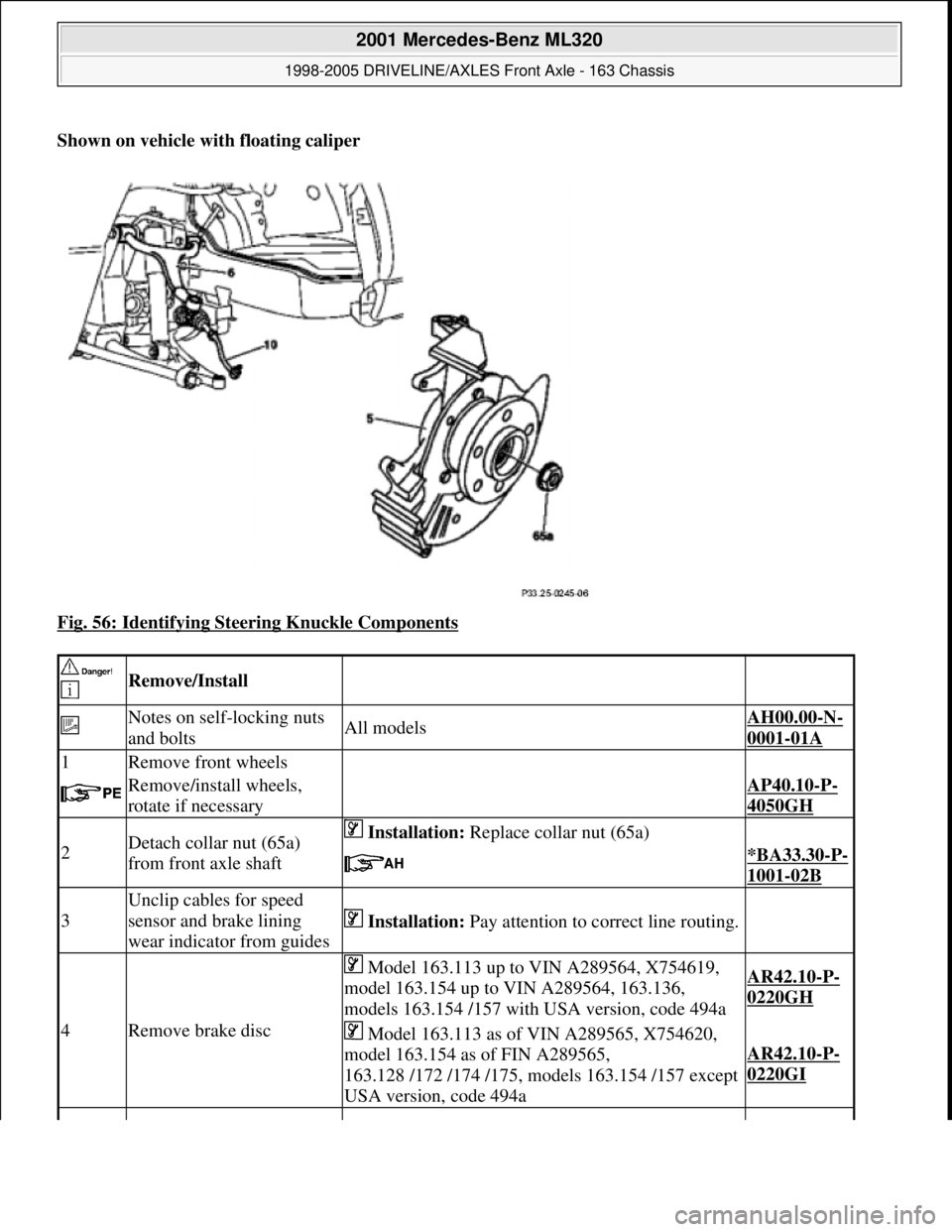
Shown on vehicle with floating caliper
Fig. 56: Identifying Steering Knuckle Components
Remove/Install
Notes on self-locking nuts
and boltsAll modelsAH00.00-N-
0001-01A
1Remove front wheels
Remove/install wheels,
rotate if necessaryAP40.10-P-
4050GH
2Detach collar nut (65a)
from front axle shaft Installation: Replace collar nut (65a)
*BA33.30-P-
1001-02B
3
Unclip cables for speed
sensor and brake lining
wear indicator from guides
Installation: Pay attention to correct line routing.
4Remove brake disc
Model 163.113 up to VIN A289564, X754619,
model 163.154 up to VIN A289564, 163.136,
models 163.154 /157 with USA version, code 494aAR42.10-P-
0220GH
Model 163.113 as of VIN A289565, X754620,
model 163.154 as of FIN A289565,
163.128 /172 /174 /175, models 163.154 /157 except
USA version, code 494a
AR42.10-P-
0220GI
2001 Mercedes-Benz ML320
1998-2005 DRIVELINE/AXLES Front Axle - 163 Chassis
me
Saturday, October 02, 2010 3:38:22 PMPage 36 © 2006 Mitchell Repair Information Company, LLC.
Page 3220 of 4133
FUNCTIONAL TEST PREPARATION
1. Check condition of fuses F16, F41, F43 and F44. See WIRING DIAGRAMS . Repair and/or replace
fuses and necessary.
2. Turn ignition on. Locate in-vehicle temperature sensor aspirator blower vent grille above anti-theft
indicator light. Place a half-inch square of tissue paper over aspirator blower vent grille. If paper stays on
vent grille, go to next step. If paper does not stay on vent grille, correct insufficient aspirator blower
ventilation.
3. Put shift lever in "P" and engage parking brake. Run engine at idle until it reaches normal operating
temperature, about 176°F (80°C). Ensure ambient (outside) temperature is greater than 58°F (15°C).
4. Manually open center and side air outlets. Ensure recirculation button is not depressed. Set blower speed
knob to position No. 1.
FUNCTION TEST
Defrost Mode
To check operation in defrost mode, set temperature selector knob to White range (vertical). Set mode control
knob to 12-o'clock position (vertical). Ensure A/C button indicator is illuminated. Air will vent from defrost and
center outlets and A/C compressor will engage. If operation is not as specified, perform the following in order:
Check voltage supply circuit Z50/2 between No. 16 fuse (15-amp) and connected components. See
VOLTAGE SUPPLY CIRCUIT Z50/2
under ELECTRICAL TESTS.
Check ground circuit. See GROUND CIRCUIT Z50/4 under ELECTRICAL TESTS.
Check in-vehicle temperature sensor signal voltage. See IN-VEHICLE TEMPERATURE SENSOR
under ELECTRICAL TESTS.
Check in-vehicle temperature sensor signal resistance. See IN-VEHICLE TEMPERATURE SENSOR
under ELECTRICAL TESTS.
Check icing protection temperature sensor signal voltage. See ICING PROTECTION
TEMPERATURE SENSOR under ELECTRICAL TESTS.
Check icing protection temperature sensor resistance. See ICING PROTECTION TEMPERATURE
SENSOR under ELECTRICAL TESTS.
Check activation voltage during temperature reduction. See ACTIVATION VOLTAGE
TEMPERATURE under ELECTRICAL TESTS.
Check activation voltage during temperature increase. See ACTIVATION VOLTAGE
TEMPERATURE under ELECTRICAL TESTS.
Check blend air flap actuator motor operation voltage. See BLEND AIR FLAP ACTUATOR MOTOR
under ELECTRICAL TESTS.
Check blend air flap actuator motor resistance. See BLEND AIR FLAP ACTUATOR MOTOR under
ELECTRICAL TESTS.
Check A/C button activation. See A/C BUTTON under ELECTRICAL TESTS.
Check A/C pressure switch. See A/C REFRIGERANT PRESSURE SWITCH under ELECTRICAL NOTE: Function test steps must be performed in order given.
2001 Mercedes-Benz ML320
2000-01 MANUAL A/C-HEATER SYSTEMS ML 320, ML 430 & ML 55
me
Saturday, October 02, 2010 3:25:10 PMPage 9 © 2006 Mitchell Repair Information Company, LLC.