1997 MERCEDES-BENZ ML350 light
[x] Cancel search: lightPage 764 of 4133
297
Fuels, coolants, lubricants etc.
Te ch n ica l
data
Instruments
and controls Operation Driving
Instrument
cluster display Practical hints Car care Index
the engine temperature will increase due to the lower
heat transfer capability of the solution. Therefore, do not
use more than this amount of anticorrosion / antifreeze.
If the coolant level is low, water and MB anticorrosion/
antifreeze should be used to bring it up to the proper
level (have cooling system checked for signs of leakage).
The water in the cooling system must meet minimum
requirements, which are usually satisfied by normal
drinking water. If your are not sure about the water
quality, consult your authorized Mercedes-Benz Light
Truck Center.
Anticorrosion/antifreeze
Your vehicle contains a number of aluminum parts. The
use of aluminum components in motor vehicle engines
necessitates that anticorrosion / antifreeze coolant used
in such engines be specifically formulated to protect the
aluminum parts. (Failure to use such anticorrosion/
antifreeze coolant will result in a significantly
shortened service life.)
Therefore the following product is strongly
recommended for use in your vehicle: Mercedes-Benz
Anticorrosion / antifreeze agent. Before the start of the winter season (or once a year in
the hot southern regions), you should have the
anticorrosion / antifreeze concentration checked. The
coolant is also regularly checked each time you bring
your vehicle to your authorized Mercedes-Benz Light
Truck Center for service.
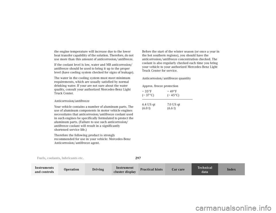
Anticorrosion / antifreeze quantity
Approx. freeze protection
– 35 °F
(– 37 °C) – 49
°F
(– 45 °C)
6.4 US qt
(6.0 l) 7. 0 U S q t
(6.6 l)
Page 772 of 4133

305
Index
Te ch n ica l
data
Instruments
and controls Operation Driving
Instrument
cluster display Practical hints Car care
Index
Headlamp cleaning system ............................................ 94
Headlights ......................................................................... 90
Heated seats ..................................................................... 44
Hood ................................................................................. 231
Hooks ............................................................................... 133
IIdentification labels .......................................................285
Illuminated vanity mirrors ............................................113
Indicator lamps in the instrument cluster ................... 78
Infant and child restraint system Installation ................................................................... 67
Infant and child restraint systems ................................ 65
Inflating the space-saver tire .......................................249
Information call See Tele Aid ............................................................... 148
Instrument cluster ........................................................... 76
Activating display ....................................................... 80
Display illumination ................................................... 80
Indicator lamps ........................................................... 78
Malfunction and indicator lamps ........................... 218
Instrument lamps ............................................................ 80 Instruments and controls ............................................... 18
Interior General notes ............................................................. 114
Interior lighting .............................................................. 110
JJump starting ................................................................. 253KKeys, vehicle .....................................................................24LLamps, exterior .............................................................. 260 Adjusting headlamp aim ......................................... 268
Auxiliary fog lamp ............................................. 92, 264
Fog lamps .....................................................................93
Headlamp assembly ......................................... 261, 262
Headlamps .................................90, 261, 262, 268, 280
High mounted stop lamp ......................................... 267
License plate lamps ................................................. 267
Low and high beam ............................................90, 263
Page 773 of 4133

306
Index
Te ch n ica l
data
Instruments
and controls Operation Driving
Instrument
cluster display Practical hints Car care
Index
Parking lamp ...................................................... 90, 264
Replacing bulbs .........................................................260
Side marker lamp ......................................................264
Standing lamp .................................................... 90, 264
Taillamp assemblies .................................................265
Turn signal lamp ................................................ 90, 264
Turn signal lamp, side .............................................266
Layout of poly-V-belt ......................................................286
Liftgate ............................................................................... 34 Unlocking ..................................................................... 28
Lighter ..............................................................................119
Limp home mode (Automatic transmission) ............. 172
Loading instructions ..................................................... 136
Lockable storage compartment .....................................116
Locking and unlocking the vehicle ............................... 27
Low engine coolant level warning ..............................224
Low engine oil level warning .......................................224
LOW RANGE Indicator lamp ........................................................... 221
LOW RANGE mode ........................................................209 LOW RANGE – 4-ETS+ .............................................204
LOW RANGE – ABS ..................................................202
LOW RANGE – ESP ...................................................208
MMaintenance ...................................................................147
Malfunction and indicator lamps in the instrument cluster ......................................................................... 218
Manual locking/unlocking the doors ...........................29
Manual operation of Skyview Top .............................. 273
Manual operation of sliding/pop-up roof .................. 272
Manual seat, front ............................................................39
MCS, radio and telephone ............................................146
Mechanical keys ............................................................... 29
Memory .............................................................................42 Recalling ....................................................................... 42
Storing ........................................................................... 42
Mirror, exterior, adjusting ..............................................73
Mirror, exterior, rear view ..............................................73
Mirror, inside, rear view ................................................. 71
Mirrors, vanity ................................................................ 113
Page 778 of 4133
311
Index
Te ch n ica l
data
Instruments
and controls Operation Driving
Instrument
cluster display Practical hints Car care
Index
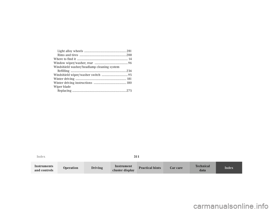
Light alloy wheels ..................................................... 281
Rims and tires ...........................................................288
Where to find it ................................................................ 14
Window wiper/washer, rear .......................................... 96
Windshield washer/headlamp cleaning system Refilling ......................................................................236
Windshield wiper/washer switch ................................. 95
Winter driving ................................................................ 181
Winter driving instructions ......................................... 180
Wiper blade
Replacing ....................................................................275
Page 780 of 4133
Service and Literature
Your authorized Mercedes-Benz Light Truck Center has trained technicians and original Mercedes-Benz parts to service your vehicle properly. For expert advice and quality service, see your authorized Mercedes-Benz Light Truck Center.
If your are interested in obtaining service literature for your vehicle, please contact your authorized Mercedes-Benz Light Truck Center. We consider this the best way for you to obtain accurate information for your vehicle.
For further information you can find us on the Mercedes-Benz web-sites www.mbusa.com and www.mbusi.com .
We reserve the right to modify the technical details of the vehicle as given in the data and illustrations of this Operator’s Manual. Reprinting, translation and copying, even of excerpts, is not permitted without our prior authorization in writing.
Title illustration no. P00.00-3059-26 Press time 10/31/00 MBNA/TI
Printed in the U.S.A.
Wa r n i n g !
To help avoid personal injury, be extremely careful when performing any service work or repairs. Improper
or incomplete service or the use of incorrect or inappropriate parts or materials may damage the vehicle or its
equipment, which may in turn result in personal injury.
If you have any question about carrying out some service, turn to the advice of an authorized Mercedes-Benz
Light Truck Center.
Page 782 of 4133
2003 ACCESSORIES/SAFETY EQUIPMENT
Mercedes-Benz - Air Bag Restraint Systems
DESCRIPTION & OPERATION
All models are equipped with Supplemental Restraint System (SRS). The main components of SRS are driver-
side air bag module, passenger-side air bag module, side impact air bag modules (located in doors), SRS control
module, side air bag sensors, SRS warning light, driver-side knee bolster, passenger-side knee bolster and seat
belt pretensioners or Emergency Tensioning Retractor (ETR) seat belt assembly. Additionally, some vehicles
may be equipped with head impact (curtain type) air bags.
Both SRS and ETR are electronically activated by a single control module. There are 2 thresholds which must
be exceeded to trigger an ETR action, air bag deployment, or both. If a moderately severe frontal collision
occurs exceeding first triggering threshold where protection from seat belt is sufficient, only Emergency
Tensioning Retractor (ETR) is activated if seat belt is buckled. If a moderately severe frontal collision occurs
exceeding first triggering threshold where protection from seat belt is sufficient, but seat belt is not buckled, air
bag is deployed and ETR is not activated.
If a severe frontal collision occurs exceeding second triggering threshold where protection from seat belt is
insufficient, air bag is deployed. ETR is activated if seat belt is buckled. If seat belt is not buckled, ETR is not
activated when second triggering threshold is reached. Passenger air bag will deploy even if passenger seat is
not occupied when a triggering threshold is exceeded. During certain types of collisions, the air bags will be
deploy, but ETRs will not be activated.
The side air bag on the driver-side deploys whenever the driver-side air bag module is deployed and when there
is a substantial side impact crash. The air bag on the passenger-side will activate only when a sensor (Occupied
Seat Recognition Sensor) in the passenger seat sends a signal to the SRS control module that the passenger-side
seat is occupied. Side air bags mounted in rear doors will deploy when side impacts occur that exceed preset
parameters.
Head impact air bag modules will deploy when certain side impacts occur that exceed preset parameters. Head
impact air bag will deploy independently of other air bags on side of impact.
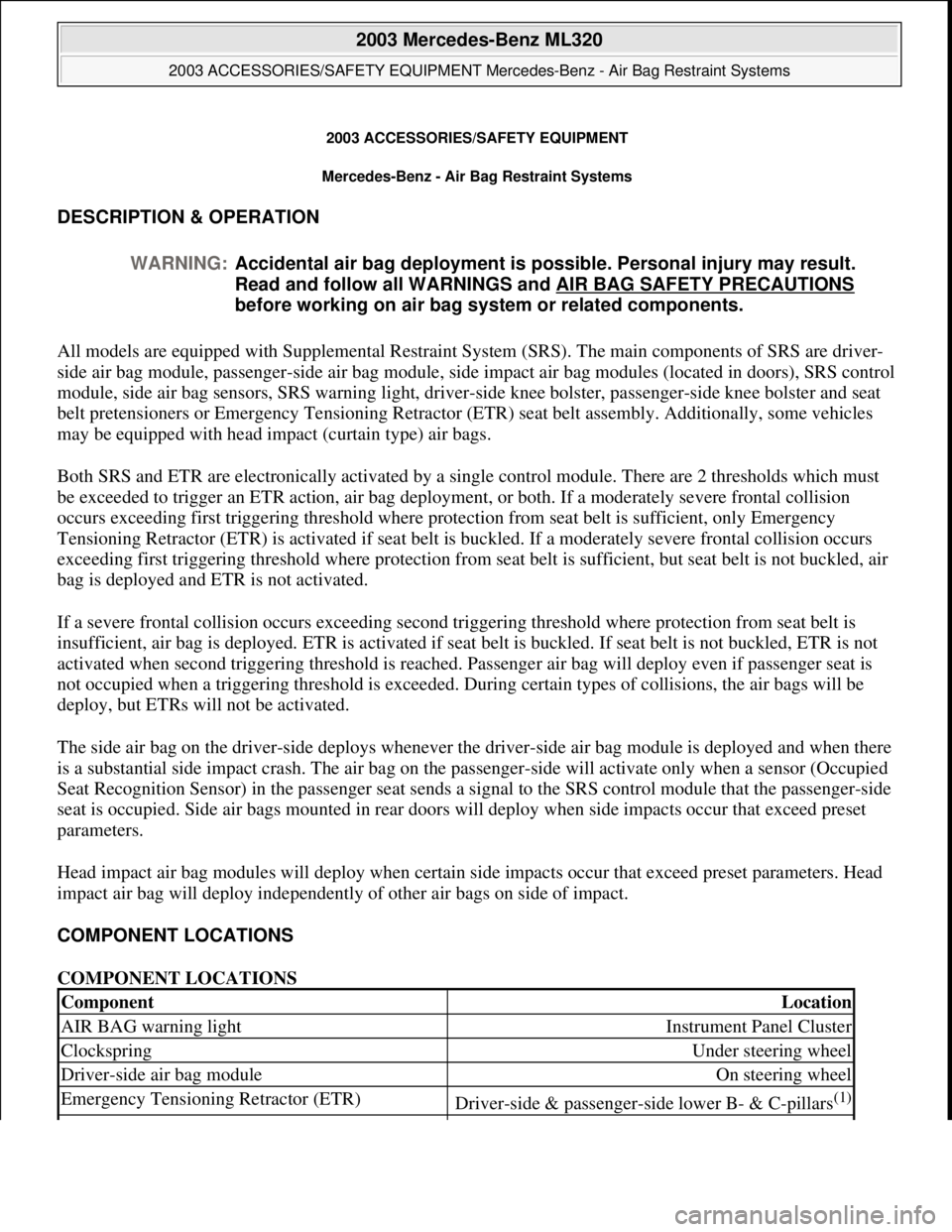
COMPONENT LOCATIONS
COMPONENT LOCATIONS WARNING:Accidental air bag deployment is possible. Personal injury may result.
Read and follow all WARNINGS and AIR BAG SAFETY PRECAUTIONS
before working on air bag system or related components.
ComponentLocation
AIR BAG warning lightInstrument Panel Cluster
ClockspringUnder steering wheel
Driver-side air bag moduleOn steering wheel
Emergency Tensioning Retractor (ETR)Driver-side & passenger-side lower B- & C-pillars(1)
2003 Mercedes-Benz ML320
2003 ACCESSORIES/SAFETY EQUIPMENT Mercedes-Benz - Air Bag Restraint Systems
2003 Mercedes-Benz ML320
2003 ACCESSORIES/SAFETY EQUIPMENT Mercedes-Benz - Air Bag Restraint Systems
me
Saturday, October 02, 2010 3:32:07 PMPage 1 © 2006 Mitchell Repair Information Company, LLC.
me
Saturday, October 02, 2010 3:32:10 PMPage 1 © 2006 Mitchell Repair Information Company, LLC.
Page 783 of 4133
SERVICING
SRS AIR BAG label on driver-side door latch post indicates SRS replacement date for air bag units. All SRS
components must be thoroughly inspected, including wiring harness. Before component replacement, check for
SRS fault codes by performing system operation check. See SYSTEM OPERATION CHECK
. SRS service
life is 10 years from manufactured date or 10 years from SRS replacement date after accident related repairs are
completed.
SYSTEM OPERATION CHECK
SRS warning light indicates SRS and Emergency Tensioning Retractor (ETR) system readiness. Turn ignition
on. SRS warning light will illuminate, then turn off after approximately 4-6 seconds indicating SRS system is
functioning properly. If SRS warning light does not illuminate, illuminates while driving or is continuously
illuminated, there is a system fault. Repair malfunctioning system.
AIR BAG SAFETY PRECAUTIONS
Observe these precautions when servicing the air bag system:
When working around SRS components and before any repairs are performed, disable air bag system. See
DISABLING & ACTIVATING AIR BAG SYSTEM
.
Before straightening any damage to body, or before performing electrical arc-welding, disable air bag
system. See DISABLING & ACTIVATING AIR BAG SYSTEM
.
Always wear safety glasses and gloves when handling a deployed air bag module. Air bag module may
contain sodium hydroxide deposits which are irritating to the skin.
Always use control module and impact sensors made by same manufacturer. Using components produced
by different manufacturers could cause accidental air bag or ETR deployment.
DO NOT repair any portion of SRS wiring harness.
If any SRS component is dropped from a height greater than 1.6 feet (0.5 m), it must be replaced.
If SRS components show signs of damage, they must be replaced.
Always handle air bag module with trim cover facing away from your body.
Always place air bag module on workbench with trim cover up, away from loose objects.
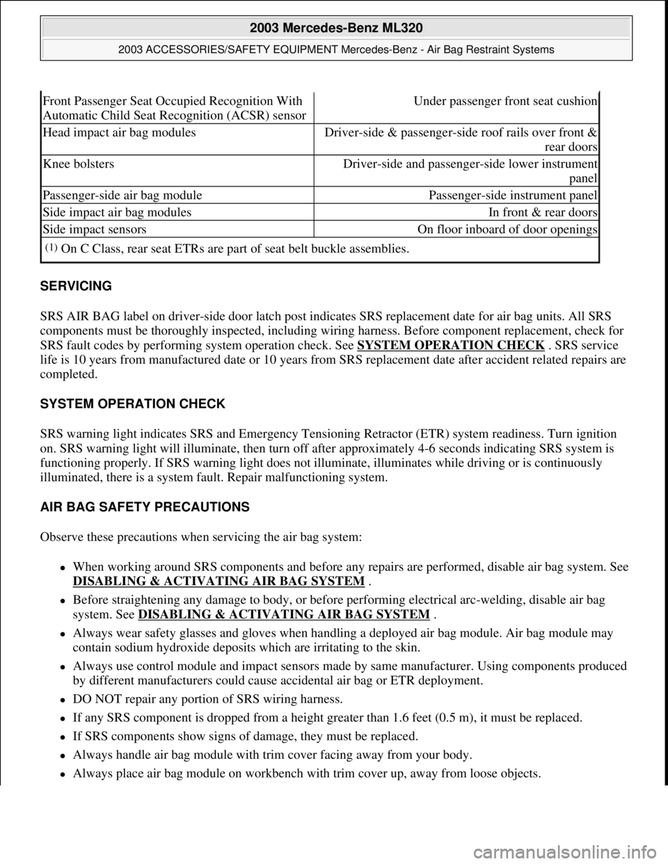
Front Passenger Seat Occupied Recognition With
Automatic Child Seat Recognition (ACSR) sensorUnder passenger front seat cushion
Head impact air bag modulesDriver-side & passenger-side roof rails over front &
rear doors
Knee bolstersDriver-side and passenger-side lower instrument
panel
Passenger-side air bag modulePassenger-side instrument panel
Side impact air bag modulesIn front & rear doors
Side impact sensorsOn floor inboard of door openings
(1)On C Class, rear seat ETRs are part of seat belt buckle assemblies.
2003 Mercedes-Benz ML320
2003 ACCESSORIES/SAFETY EQUIPMENT Mercedes-Benz - Air Bag Restraint Systems
me
Saturday, October 02, 2010 3:32:07 PMPage 2 © 2006 Mitchell Repair Information Company, LLC.
Page 786 of 4133
2004 ACCESSORIES/SAF ETY EQUIPMENT
Mercedes-Benz - Air Bag Restraint Systems
DESCRIPTION & OPERATION
The main components of Supplemental Restraint System (SRS) are dual-stage driver-side and passenger-side
air bag modules, side impact air bag modules, head impact air bag modules , SRS control module, side impact
sensors, AIR BAG warning light, driv er-side and passenger-side Emergency Tensioning Retractors (ETR). See
COMPONENT LOCATIONS
.
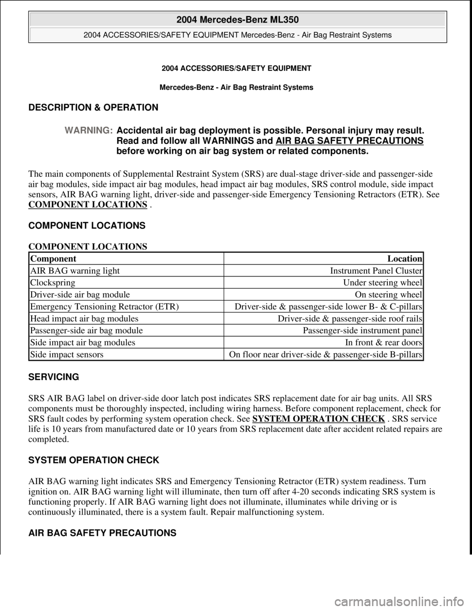
COMPONENT LOCATIONS
COMPONENT LOCATIONS
SERVICING
SRS AIR BAG label on driver-side door latch post indicates SRS replacement date for air bag units. All SRS
components must be thoroughly inspected, including wiring harness. Before component replacement, check for
SRS fault codes by performing system operation check. See SYSTEM OPERATION CHECK
. SRS service
life is 10 years from manufactured da te or 10 years from SRS replacement date after accident related repairs are
completed.
SYSTEM OPERATION CHECK
AIR BAG warning light indicates SRS and Emergency Te nsioning Retractor (ETR) system readiness. Turn
ignition on. AIR BAG warning light will illuminate, then turn off after 4-20 seconds indicating SRS system is
functioning properly. If AIR BAG warn ing light does not illuminate, illuminates while driving or is
continuously illuminated, ther e is a system fault. Repair malfunctioning system.
AIR BAG SAFETY PRECAUTIONS
WARNING:
Accidental air bag deployment is pos sible. Personal injury may result.
Read and follow all WARNINGS and AIR BAG SAFETY PRECAUTIONS
before working on ai r bag system or related components.
ComponentLocation
AIR BAG warning lightInstrument Panel Cluster
ClockspringUnder steering wheel
Driver-side air bag moduleOn steering wheel
Emergency Tensioning Retractor (ETR)Driver-side & passenger-si de lower B- & C-pillars
Head impact air bag modulesDriver-side & passenger-side roof rails
Passenger-side air bag modulePassenger-side instrument panel
Side impact air bag modulesIn front & rear doors
Side impact sensorsOn floor near driver-side & passenger-side B-pillars
2004 Mercedes-Benz ML350
2004 ACCESSORIES/SAFETY EQUIPMENT Merce des-Benz - Air Bag Restraint Systems
2004 Mercedes-Benz ML350
2004 ACCESSORIES/SAFETY EQUIPMENT Mercedes-Benz - Air Bag Restraint Systems
me
Saturday, October 02, 2010 3:40:40 PMPage 1 © 2006 Mitchell Repair Information Company, LLC.
me
Saturday, October 02, 2010 3:40:43 PMPage 1 © 2006 Mitchell Repair Information Company, LLC.