1997 MERCEDES-BENZ ML350 water pump
[x] Cancel search: water pumpPage 2458 of 4133
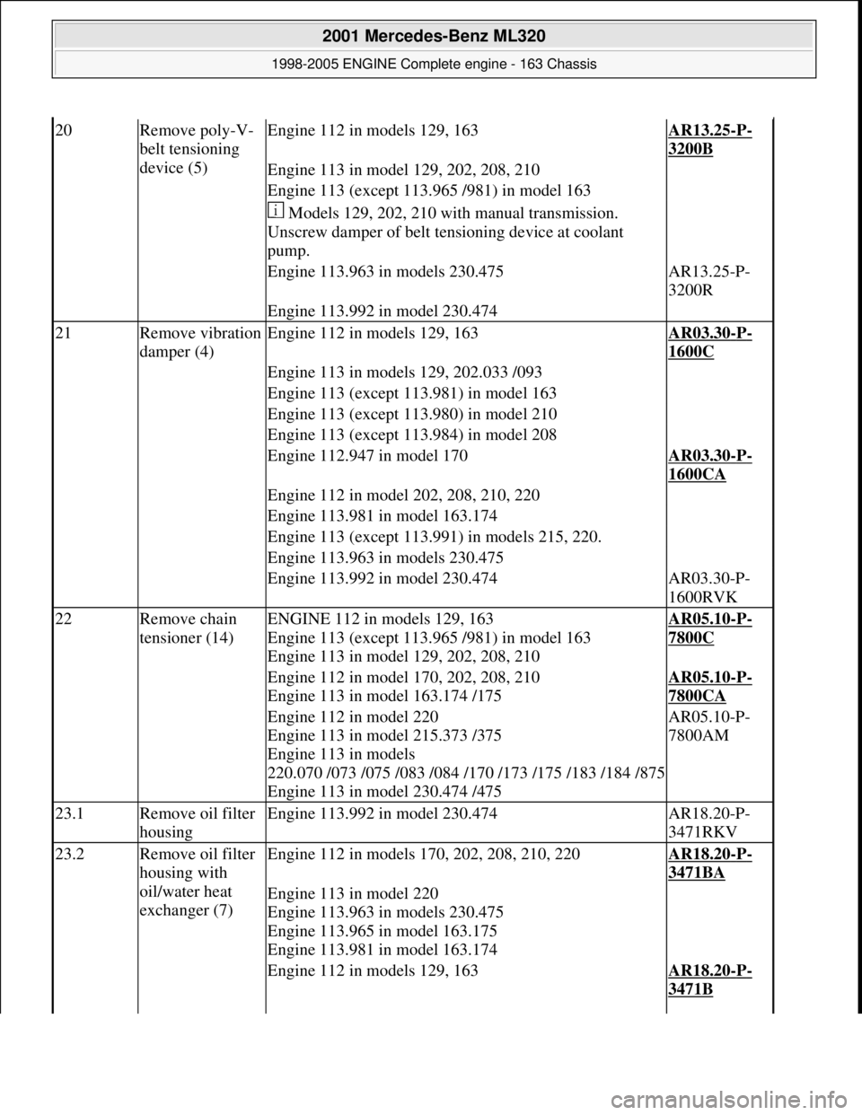
20Remove poly-V-
belt tensioning
device (5)Engine 112 in models 129, 163AR13.25-P-
3200B
Engine 113 in model 129, 202, 208, 210
Engine 113 (except 113.965 /981) in model 163
Models 129, 202, 210 with manual transmission.
Unscrew damper of belt te nsioning device at coolant
pump.
Engine 113.963 in models 230.475AR13.25-P-
3200R
Engine 113.992 in model 230.474
21Remove vibration
damper (4)Engine 112 in models 129, 163AR03.30-P-
1600C
Engine 113 in models 129, 202.033 /093
Engine 113 (except 113.981) in model 163
Engine 113 (except 113.980) in model 210
Engine 113 (except 113.984) in model 208
Engine 112.947 in model 170AR03.30-P-
1600CA
Engine 112 in model 202, 208, 210, 220
Engine 113.981 in model 163.174
Engine 113 (except 113.991) in models 215, 220.
Engine 113.963 in models 230.475
Engine 113.992 in model 230.474AR03.30-P-
1600RVK
22Remove chain
tensioner (14)ENGINE 112 in models 129, 163
Engine 113 (except 113.965 /981) in model 163
Engine 113 in model 129, 202, 208, 210AR05.10-P-
7800C
Engine 112 in model 170, 202, 208, 210
Engine 113 in model 163.174 /175AR05.10-P-
7800CA
Engine 112 in model 220
Engine 113 in model 215.373 /375
Engine 113 in models
220.070 /073 /075 /083 /084 /170 /173 /175 /183 /184 /875
Engine 113 in model 230.474 /475AR05.10-P-
7800AM
23.1Remove oil filter
housingEngine 113.992 in model 230.474AR18.20-P-
3471RKV
23.2Remove oil filter
housing with
oil/water heat
exchanger (7)Engine 112 in models 170, 202, 208, 210, 220AR18.20-P-
3471BA
Engine 113 in model 220
Engine 113.963 in models 230.475
Engine 113.965 in model 163.175
Engine 113.981 in model 163.174
Engine 112 in models 129, 163AR18.20-P-
3471B
2001 Mercedes-Benz ML320
1998-2005 ENGINE Complete engine - 163 Chassis
me
Saturday, October 02, 2010 3:17:57 PMPage 102 © 2006 Mitchell Repair Information Company, LLC.
Page 2464 of 4133
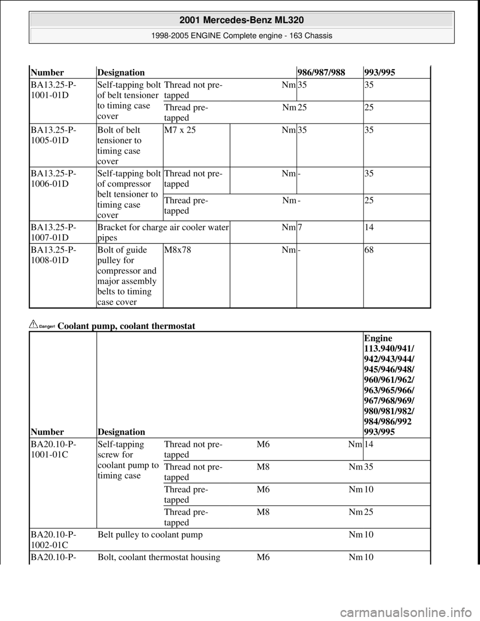
Coolant pump, coolant thermostat
NumberDesignation986/987/988993/995
BA13.25-P-
1001-01DSelf-tapping bolt
of belt tensioner
to timing case
coverThread not pre-
tappedNm3535
Thread pre-
tappedNm2525
BA13.25-P-
1005-01DBolt of belt
tensioner to
timing case
coverM7 x 25Nm3535
BA13.25-P-
1006-01DSelf-tapping bolt
of compressor
belt tensioner to
timing case
coverThread not pre-
tappedNm-35
Thread pre-
tappedNm-25
BA13.25-P-
1007-01DBracket for charge air cooler water
pipesNm714
BA13.25-P-
1008-01DBolt of guide
pulley for
compressor and
major assembly
belts to timing
case coverM8x78Nm-68
NumberDesignation
Engine
113.940/941/
942/943/944/
945/946/948/
960/961/962/
963/965/966/
967/968/969/
980/981/982/
984/986/992
993/995
BA20.10-P-
1001-01CSelf-tapping
screw for
coolant pump to
timing caseThread not pre-
tappedM6Nm14
Thread not pre-
tappedM8Nm35
Thread pre-
tappedM6Nm10
Thread pre-
tappedM8Nm25
BA20.10-P-
1002-01CBelt pulley to coolant pumpNm10
BA20.10-P- Bolt, coolant thermostat housing M6 Nm
10
2001 Mercedes-Benz ML320
1998-2005 ENGINE Complete engine - 163 Chassis
me
Saturday, October 02, 2010 3:17:57 PMPage 108 © 2006 Mitchell Repair Information Company, LLC.
Page 2610 of 4133

21
Detach rear brake cables
Unclip at underfloor of vehicle and
unscrew brake cable holder on right and left
at frame.
22.1
Unbolt check strap of rear axle carrier from
underfloor of vehicle
As of VIN A145273, X708319.
23
Remove left rear stone shield
24
Remove lower tensioning straps (80/2) and
loosen the upper tensioning straps
Tensioning straps are color-coded and
cannot be mixed up.
Support fuel tank using assembly jack.
*BA47.10-P-1001-01D
25
Remove longitudinal strut for tensioning
straps (80/18)
*BA47.10-P-1002-01D
26.1
Unscrew linkage for headlamp range
adjustment
at the top
If installed.
27
Unscrew nuts on bottom of the shock
absorbers at the transverse control arm
Installation:
Install new self-locking nuts.
*BA32.25-P-1001-03D
28
Unscrew rear axle carrier from floor of vehicle
and lower as far as possible
Support rear axle carrier.
Installation:
Install new self-locking bolts.
*BA35.10-P-1001-01C
29
Lower fuel tank
Support fuel tank.
30
Remove upper tensioning strap
at the rear
The tensioning strap at the top at the front.
31.1
Unclip lines from side of fuel tank
As of VIN A289565, X754620.
Installation:
The lines must not be
damaged.
32
Disconnect fuel pump electrical plug
connection
33
Disconnect fuel feed line (90/12) and fuel
return line (90/11)
Fuel lines must not be bent.
Pliers
*163589003700
34
Remove fuel tank (80)
Installation:
Ensure that the sealing
rubbers (5) seat correctly in the body floor to
prevent water entry.
Do not damage fuel lines at filler neck.
Guide filler neck with its chamfered side
(arrow) through between frame and body.
Filler neck and fuel tank cannot be separated
from each other.
35
Install in the reverse order
36.1
Dispose of fuel tank
Ony when replacing the fuel tank.
o
Disposal of fuel tanks
OS47.10-P-0001-01A
Rear axle carrier
Number
Designation
Model
Series 163
BA35.10-P-1001-01C
Self-locking bolt, rear axle carrier at front and rear
to frame floor
Nm
200
Propeller shaft
Number
Designation
Model
Series 163
BA41.10-P-1002-01C
Self-locking bolt, rear propsharft
at rear axle center section
Nm
50
Copyright DaimlerChrysler AG 28.05.2006 CD-Ausgabe G/10/04 . This WIS print-out will not be recorde
d by Modification services.
Page 3
Page 2665 of 4133
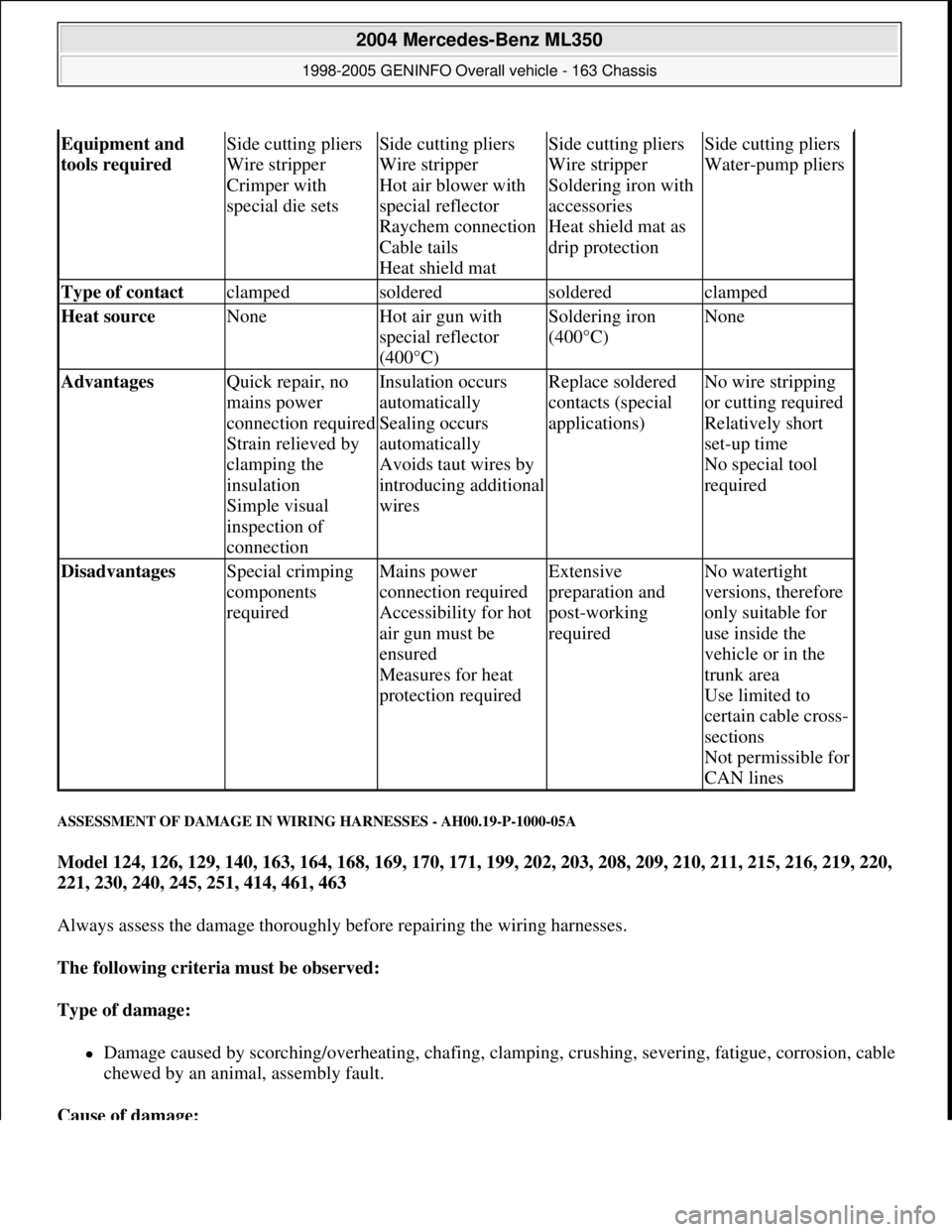
ASSESSMENT OF DAMAGE IN WIRING HARNESSES - AH00.19-P-1000-05A
Model 124, 126, 129, 140, 163, 164, 168, 169, 170, 171, 199, 202, 203, 208, 209, 210, 211, 215, 216, 219, 220,
221, 230, 240, 245, 251, 414, 461, 463
Always assess the damage thoroughly before repairing the wiring harnesses.
The following criteria must be observed:
Type of damage:
Damage caused by scorching/overheating, chafing, clamping, crushing, severing, fatigue, corrosion, cable
chewed by an animal, assembly fault.
Cause of damage:
Equipment and
tools required Side cutting pliers
Wire stripper
Crimper with
special die setsSide cutting pliers
Wire stripper
Hot air blower with
special reflector
Raychem connection
Cable tails
Heat shield matSide cutting pliers
Wire stripper
Soldering iron with
accessories
Heat shield mat as
drip protectionSide cutting pliers
Water-pump pliers
Type of contact clampedsolderedsolderedclamped
Heat source NoneHot air gun with
special reflector
(400°C)Soldering iron
(400°C)None
Advantages Quick repair, no
mains power
connection required
Strain relieved by
clamping the
insulation
Simple visual
inspection of
connectionInsulation occurs
automatically
Sealing occurs
automatically
Avoids taut wires by
introducing additional
wiresReplace soldered
contacts (special
applications)No wire stripping
or cutting required
Relatively short
set-up time
No special tool
required
Disadvantages Special crimping
components
requiredMains power
connection required
Accessibility for hot
air gun must be
ensured
Measures for heat
protection requiredExtensive
preparation and
post-working
requiredNo watertight
versions, therefore
only suitable for
use inside the
vehicle or in the
trunk area
Use limited to
certain cable cross-
sections
Not permissible for
CAN lines
2004 Mercedes-Benz ML350
1998-2005 GENINFO Overall vehicle - 163 Chassis
me
Saturday, October 02, 2010 3:47:44 PMPage 20 © 2006 Mitchell Repair Information Company, LLC.
Page 3287 of 4133
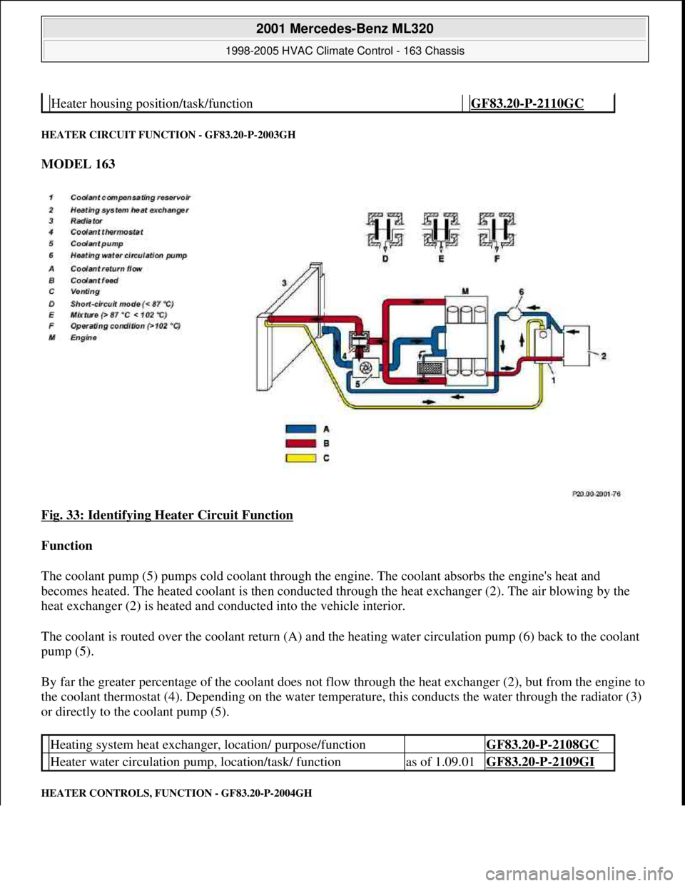
HEATER CIRCUIT FUNCTION - GF83.20-P-2003GH
MODEL 163
Fig. 33: Identifying Heater Circuit Function
Function
The coolant pump (5) pumps cold coolant through the engine. The coolant absorbs the engine's heat and
becomes heated. The heated coolant is then conducted through the heat exchanger (2). The air blowing by the
heat exchanger (2) is heated and conducted into the vehicle interior.
The coolant is routed over the coolant return (A) and the heating water circulation pump (6) back to the coolant
pump (5).
By far the greater percentage of the coolant does not flow through the heat exchanger (2), but from the engine to
the coolant thermostat (4). Depending on the water temperature, this conducts the water through the radiator (3)
or directly to the coolant pump (5).
HEATER CONTROLS, FUNCTION - GF83.20-P-2004GH
Heater housing position/task/function GF83.20-P-2110GC
Heating system heat exchanger, location/ purpose/function GF83.20-P-2108GC
Heater water circulation pump, location/task/ functionas of 1.09.01GF83.20-P-2109GI
2001 Mercedes-Benz ML320
1998-2005 HVAC Climate Control - 163 Chassis
me
Saturday, October 02, 2010 3:23:15 PMPage 43 © 2006 Mitchell Repair Information Company, LLC.
Page 3289 of 4133
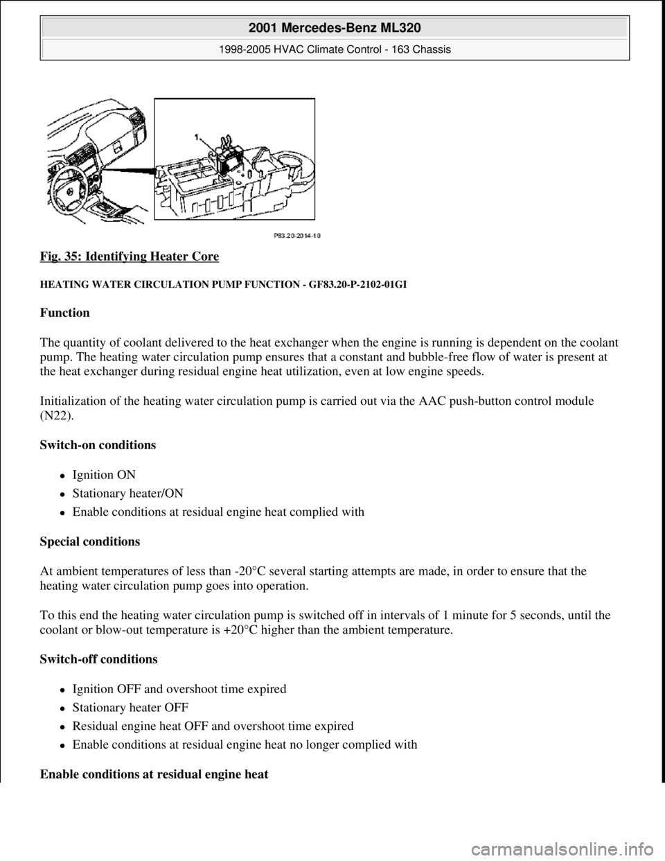
Fig. 35: Identifying Heater Core
HEATING WATER CIRCULATION PUMP FUNCTION - GF83.20-P-2102-01GI
Function
The quantity of coolant delivered to the heat exchanger when the engine is running is dependent on the coolant
pump. The heating water circulation pump ensures that a constant and bubble-free flow of water is present at
the heat exchanger during residual engine heat utilization, even at low engine speeds.
Initialization of the heating water circulation pump is carried out via the AAC push-button control module
(N22).
Switch-on conditions
Ignition ON
Stationary heater/ON
Enable conditions at residual engine heat complied with
Special conditions
At ambient temperatures of less than -20°C several starting attempts are made, in order to ensure that the
heating water circulation pump goes into operation.
To this end the heating water circulation pump is switched off in intervals of 1 minute for 5 seconds, until the
coolant or blow-out temperature is +20°C higher than the ambient temperature.
Switch-off conditions
Ignition OFF and overshoot time expired
Stationary heater OFF
Residual engine heat OFF and overshoot time expired
Enable conditions at residual engine heat no longer complied with
Enable conditions at residual engine heat
2001 Mercedes-Benz ML320
1998-2005 HVAC Climate Control - 163 Chassis
me
Saturday, October 02, 2010 3:23:15 PMPage 45 © 2006 Mitchell Repair Information Company, LLC.
Page 3290 of 4133
The heating water circulation pump runs in any event 1 minute after starting residual engine heat operation. The
overshoot conditions at least will be fulfilled.
Overshoot conditions
Coolant temperature 100°C --> overshoot time 5 minutes
Coolant temperature >100°C --> overshoot time 10 minutes
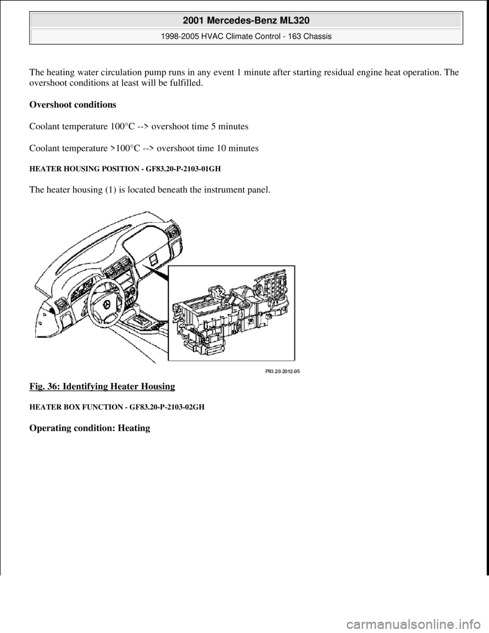
HEATER HOUSING POSITION - GF83.20-P-2103-01GH
The heater housing (1) is located beneath the instrument panel.
Fig. 36: Identifying Heater Housing
HEATER BOX FUNCTION - GF83.20-P-2103-02GH
Operating condition: Heating
2001 Mercedes-Benz ML320
1998-2005 HVAC Climate Control - 163 Chassis
me
Saturday, October 02, 2010 3:23:15 PMPage 46 © 2006 Mitchell Repair Information Company, LLC.
Page 3295 of 4133
The fresh air/recirculated air flap shuts off the supply of recirculated air.
Fresh air is drawn in.
Recirculation mode
The fresh air/recirculated air flap shuts off the supply of fresh air. Air is drawn in from the passenger
compartment.
HEATER CORE, LOCATION/PURPOSE/FUNCTION - GF83.20-P-2108GC
MODEL 163, 168
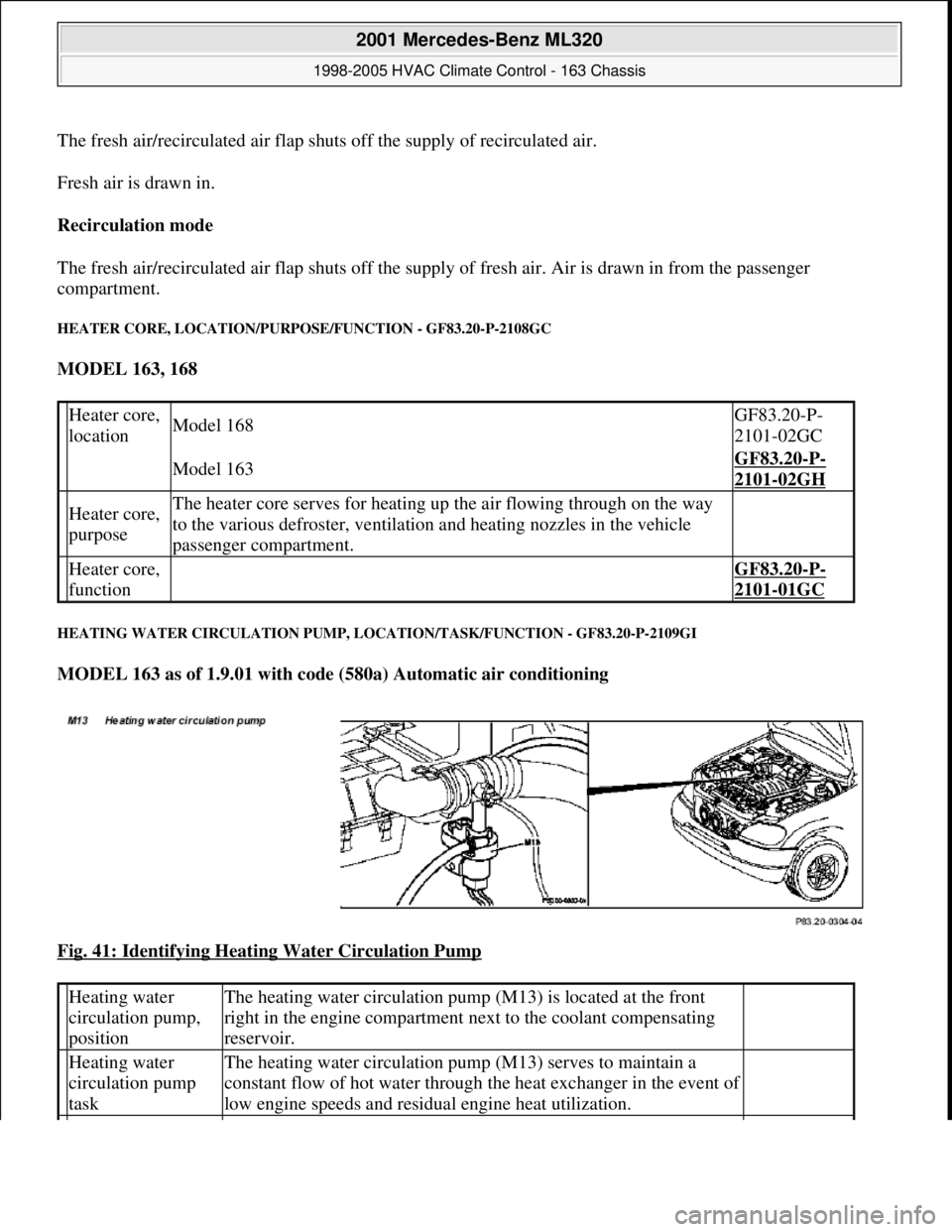
HEATING WATER CIRCULATION PUMP, LOCATION/TASK/FUNCTION - GF83.20-P-2109GI
MODEL 163 as of 1.9.01 with code (580a) Automatic air conditioning
Fig. 41: Identifying Heating Water Circulation Pump
Heater core,
locationModel 168GF83.20-P-
2101-02GC
Model 163GF83.20-P-
2101-02GH
Heater core,
purposeThe heater core serves for heating up the air flowing through on the way
to the various defroster, ventilation and heating nozzles in the vehicle
passenger compartment.
Heater core,
function GF83.20-P-
2101-01GC
Heating water
circulation pump,
positionThe heating water circulation pump (M13) is located at the front
right in the engine compartment next to the coolant compensating
reservoir.
Heating water
circulation pump
taskThe heating water circulation pump (M13) serves to maintain a
constant flow of hot water through the heat exchanger in the event of
low engine speeds and residual engine heat utilization.
2001 Mercedes-Benz ML320
1998-2005 HVAC Climate Control - 163 Chassis
me
Saturday, October 02, 2010 3:23:15 PMPage 51 © 2006 Mitchell Repair Information Company, LLC.