Page 2316 of 4133
Fig. 79: Identifying Replacem ent Of Valve Stem Seals - Shown On Engine 111
Engines 112, 113
Shown on Engine 112
1. Use pliers (1) to pull of f valve stem seals (86)
2. Check surface of valve stems for roughness and format ion of burrs (visual inspection or with a nail).
Replace valves with a rough stem surface or formation of burrs.
3. Fit protective sleeve (2) onto valve stem.
4. Oil valve stem seals (86).
5. Press on the valve stem seal s (86) with a drift (3).
2004 Mercedes-Benz ML350
1998-2005 ENGINE Engine timing - 163 Chassis
me
Saturday, October 02, 2010 3:39:38 PMPage 75 © 2006 Mitchell Repair Information Company, LLC.
Page 2317 of 4133
Fig. 80: Identifying Replacem ent Of Valve Stem Seals - Shown On Engine 112
REMOVE/INSTALL VALVE SPRINGS AND / OR VALVE STEM SEALS - AR05.30-P-3500B
ENGINE 112.945 in MODELS 463.209 /232 /233 /244 /245 /250
ENGINE 112 in MODELS 129, 163
ENGINE 113.962 in MODELS 463.206 / 240 /241 /247 /248 /249 /254
ENGINE 113 in MODELS 129, 163, 202, 208, 210
ENGINE 113.982 in MODELS 463.243 /246
2004 Mercedes-Benz ML350
1998-2005 ENGINE Engine timing - 163 Chassis
me
Saturday, October 02, 2010 3:39:38 PMPage 76 © 2006 Mitchell Repair Information Company, LLC.
Page 2318 of 4133
Fig. 81: Identifying Valve Springs And / Or Valve Stem Seal Components - Shown On Engine 112 In
Model 129
Shown on ENGINE 112 in MODEL 129
2004 Mercedes-Benz ML350
1998-2005 ENGINE Engine timing - 163 Chassis
me
Saturday, October 02, 2010 3:39:38 PMPage 77 © 2006 Mitchell Repair Information Company, LLC.
Page 2319 of 4133
Fig. 82: Identifying Valve Springs And / Or Valve Stem Seal Components - Shown On Engine 112 (1 Of
2)
Shown on engine 112
Shown on engine 112
2004 Mercedes-Benz ML350
1998-2005 ENGINE Engine timing - 163 Chassis
me
Saturday, October 02, 2010 3:39:38 PMPage 78 © 2006 Mitchell Repair Information Company, LLC.
Page 2320 of 4133

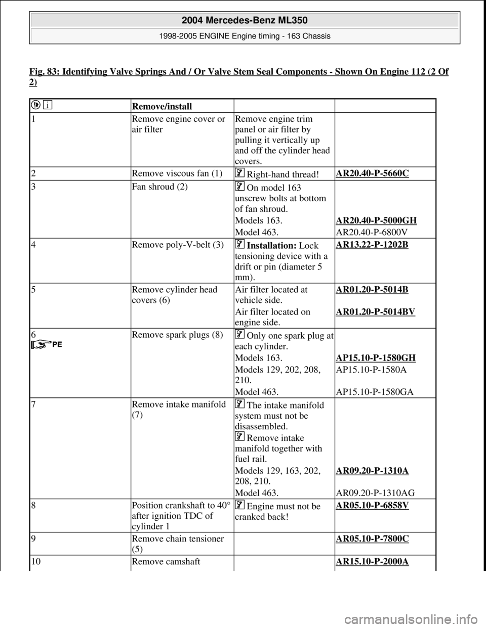
Fig. 83: Identifying Valve Springs And / Or Valve Stem Seal Components -Shown On Engine 112 (2 Of
2)
Remove/install
1Remove engine cover or
air filterRemove engine trim
panel or air filter by
pulling it vertically up
and off the cylinder head
covers.
2Remove viscous fan (1) Right-hand thread!AR20.40-P-5660C
3Fan shroud (2) On model 163
unscrew bolts at bottom
of fan shroud.
Models 163.AR20.40-P-5000GH
Model 463.AR20.40-P-6800V
4Remove poly-V-belt (3) Installation: Lock
tensioning device with a
drift or pin (diameter 5
mm).AR13.22-P-1202B
5Remove cylinder head
covers (6)Air filter located at
vehicle side.AR01.20-P-5014B
Air filter located on
engine side.AR01.20-P-5014BV
6
Remove spark plugs (8)Only one spark plug at
each cylinder.
Models 163.AP15.10-P-1580GH
Models 129, 202, 208,
210.AP15.10-P-1580A
Model 463.AP15.10-P-1580GA
7Remove intake manifold
(7) The intake manifold
system must not be
disassembled.
Remove intake
manifold together with
fuel rail.
Models 129, 163, 202,
208, 210.AR09.20-P-1310A
Model 463.AR09.20-P-1310AG
8Position crankshaft to 40°
after ignition TDC of
cylinder 1 Engine must not be
cranked back!AR05.10-P-6858V
9Remove chain tensioner
(5) AR05.10-P-7800C
10Remove camshaft AR15.10-P-2000A
2004 Mercedes-Benz ML350
1998-2005 ENGINE Engine timing - 163 Chassis
me
Saturday, October 02, 2010 3:39:38 PMPage 79 © 2006 Mitchell Repair Information Company, LLC.
Page 2321 of 4133

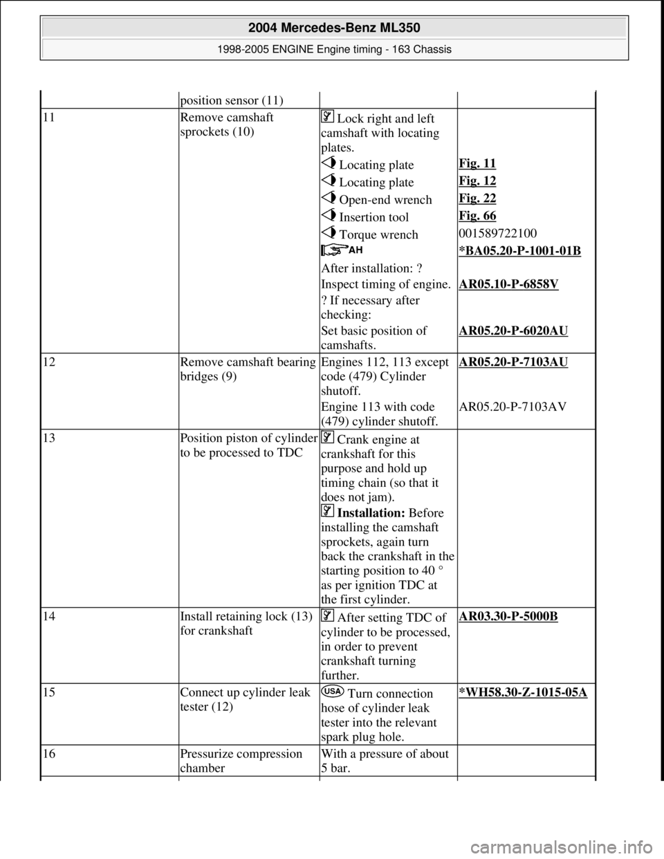
position sensor (11)
11Remove camshaft
sprockets (10) Lock right and left
camshaft with locating
plates.
Locating plateFig. 11
Locating plateFig. 12
Open-end wrenchFig. 22
Insertion toolFig. 66
Torque wrench001589722100
*BA05.20-P-1001-01B
After installation: ?
Inspect timing of engine.AR05.10-P-6858V
? If necessary after
checking:
Set basic position of
camshafts.AR05.20-P-6020AU
12Remove camsha ft bearing
bridges (9)Engines 112, 113 except
code (479) Cylinder
shutoff.AR05.20-P-7103AU
Engine 113 with code
(479) cylinder shutoff.AR05.20-P-7103AV
13Position piston of cylinder
to be processed to TDC Crank engine at
crankshaft for this
purpose and hold up
timing chain (so that it
does not jam).
Installation: Before
installing the camshaft
sprockets, again turn
back the crankshaft in the
starting position to 40 °
as per ignition TDC at
the first cylinder.
14Install retaining lock (13)
for crankshaft After setting TDC of
cylinder to be processed,
in order to prevent
crankshaft turning
further.AR03.30-P-5000B
15Connect up cylinder leak
tester (12) Turn connection
hose of cylinder leak
tester into the relevant
spark plug hole.*WH58.30-Z-1015-05A
16Pressurize compression
chamberWith a pressure of about
5 bar.
2004 Mercedes-Benz ML350
1998-2005 ENGINE Engine timing - 163 Chassis
me
Saturday, October 02, 2010 3:39:38 PMPage 80 © 2006 Mitchell Repair Information Company, LLC.
Page 2322 of 4133

Camshaft
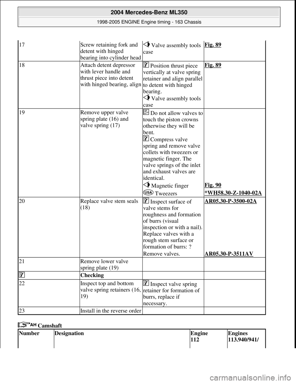
17Screw retaining fork and
detent with hinged
bearing into cylinder head Valve assembly tools
caseFig. 89
18Attach detent depressor
with lever handle and
thrust piece into detent
with hinged bearing, align Position thrust piece
vertically at valve spring
retainer and align parallel
to detent with hinged
bearing.
Valve assembly tools
caseFig. 89
19Remove upper valve
spring plate (16) and
valve spring (17)Do not allow valves to
touch the piston crowns
otherwise they will be
bent.
Compress valve
spring and remove valve
collets with tweezers or
magnetic finger. The
valve springs of the inlet
and exhaust valves are
identical.
Magnetic fingerFig. 90
Tweezers*WH58.30-Z-1040-02A
20Replace valve stem seals
(18) Inspect surface of
valve stems for
roughness and formation
of burrs (visual
inspection or with a nail).
Replace valves with a
rough stem surface or
formation of burrs: ?AR05.30-P-3500-02A
Remove valves.AR05.30-P-3511AV
21Remove lower valve
spring plate (19)
Checking
22Inspect top and bottom
valve spring retainers (16,
19) Inspect valve spring
retainer for formation of
burrs, replace if
necessary.
23Install in the reverse order
NumberDesignationEngine
112 Engines
113.940/941/
2004 Mercedes-Benz ML350
1998-2005 ENGINE Engine timing - 163 Chassis
me
Saturday, October 02, 2010 3:39:38 PMPage 81 © 2006 Mitchell Repair Information Company, LLC.
Page 2323 of 4133
Fig. 84: Identifying Locating Plate (112 589 00 32 00)
Fig. 85: Identifying Locating Plate (112 589 01 32 00)
Fig. 86: Identifying Open End Wrench (112 589 00 01 00)
except
112.951/976942/943/944/
948/961/962/
963/964/965/
966/967/968/
969/971/980/
981/982/984/
986/992/995
BA05.20-P-
1001-01BBolt for
camshaft
sprocketM12x45Stage 1Nm5050
Stage 2Angle°9090
2004 Mercedes-Benz ML350
1998-2005 ENGINE Engine timing - 163 Chassis
me
Saturday, October 02, 2010 3:39:38 PMPage 82 © 2006 Mitchell Repair Information Company, LLC.