1997 MERCEDES-BENZ ML320 wheel torque
[x] Cancel search: wheel torquePage 1392 of 4133
Torque from the torque converter is increased via the propeller shaft (1) and all three planetary gearsets and
transferred with reversed direction of rotation to the output shaft (5). See Fig. 129
.
The following are not engaged:
Rear Multi-Disk Brake (B2)
Freewheel F2
Front Multi-Disk Clutch (K1)
Front Planetary Gear Set.
The input shaft (1) drive the internal gear (V4). In drive mode the sun gear (V1) is supported via the locked
freewheel (F1) and in overrun mode in the housing via the engaged front multi-disk brake (B1). The planet
gears (V2) roll over the fixed sun gear (V1) and provide an increase in torque between the internal gear (V4)
and the planet carrier (V3). The planet carrier (V3) moves at reduced speed in the direction of engine rotation.
Rear Planetary Gear Set.
The planet carrier (H3) is held securely in the housing due to the engaged center multi-disk brake (B3). The
internal gear (H4) turns at a reduced speed because of its mechanical connection to the front planet carrier (V3).
The planet gears (H2) turn between the ring gear (H4) and the sun gear (H1). The direction is reversed due to
the securely held planet carrier (H3) so that the sun gear (H1) rotates in the opposite direction to the engine.
Center Planetary Gear Set.
The hollow gear (M4) is held securely in the housing by the center multi-disk brake (B3) via the mechanical
connection to the planet carrier (H3). The sun gear (M1) rotates backwards due to the engaged rear multi-disk
clutch (K3). The planet gears (M2) roll over the fixed internal gear (M4) and provide an increase in torque
between the sun gear (M1) and the planet carrier (M3). The output shaft (5) connected to the planet carrier (M3)
turns at a reduced speed in the opposite direction to the running direction of the engine.
Torque Converter, Location/Task/Design/Function
See TORQUE CONVERTER, LOCATION/TASK/DESIGN/FUNCTION
.
Planetary Gear Set, Location/Task/Design/Function
See PLANETARY GEAR SET, LOCATION/TASK/DESIGN/FUNCTION
. .
Multiple-Disc Brake, Location/Task/Design/Function
See MULTIPLE
-DISC BRAKE, LOCATION/TASK/DESIGN/FUNCTION.
Multi-Plate Clutch, Location/Task/Design/Function
See MULTI
-PLATE CLUTCH, LOCATION/TASK/DESIGN/FUNCTION.
2001 Mercedes-Benz ML320
1998-03 AUTOMATIC TRANSMISSIONS Complete Transmissions - ML 320 - 722.662
me
Saturday, October 02, 2010 3:15:28 PMPage 223 © 2006 Mitchell Repair Information Company, LLC.
Page 1393 of 4133
Location/Task/Design/Function Of Freewheel
See LOCATION/TASK/DESIGN/FUNCTION OF FREEWHEEL
.
Function Of Gear Shift (With Touch Shift)
Transmission with touch shift.
On transmission 722.6 the electrohydraulic control unit converts the electric signals going out from the
electronic transmission control (EGS) into hydraulic signals.
Faults occurring in the ETC control unit (N15/3) are handled by the limp-home system. The limp-home system
is designed so that the driver can reach a Service Operation even under extreme conditions.
Selector lever position "P", "R", "N" and "D" are transmitted by the electronic selector lever module control unit
(N15/5) on the Controller Area Network bus class C (engine compartment) (CAN-C) and in parallel to this by
means of a shift rod to the range selector lever at the transmission end. By touching or holding the selector lever
towards "+" or "-" the shift range is pre-selected and displayed in the instrument cluster (A1) until an upshift of
transmission 722.6 is possible.
Function Of Gear Change
See FUNCTION OF GEAR CHANGE
.
Emergency Default Mode, Function
See LIMP
-HOME MODE, FUNCTION.
Function Of Manual Drive Mode Selection
Oil Level Control, Function
See OIL LEVEL CONTROL, FUNCTION
.
Torque Converter Lockup Clutch Control, Function
See FUNCTION OF TORQUE CONVERTER LOCKUP CLUTCH CONTROL
.
Function Of Gear Shift (Without Touch Shift)
On transmission 722.6 the electrohydraulic control unit converts the electric signals going out from the
electronic transmission control (EGS) into hydraulic signals.
Faults occurring in the ETC control unit (N15/3) are handled by the limp-home system. The limp-home system
is designed so that the driver can reach a Service Operation even under extreme conditions.
Selector lever position "P", "R", "N" and "D" are transmitted by the electronic selector lever module control unit
2001 Mercedes-Benz ML320
1998-03 AUTOMATIC TRANSMISSIONS Complete Transmissions - ML 320 - 722.662
me
Saturday, October 02, 2010 3:15:28 PMPage 224 © 2006 Mitchell Repair Information Company, LLC.
Page 1449 of 4133
The ETC control module (N15/3) determines the instantaneous operating condition of the vehicle and controls
all gearshift sequences taking into account the ease of shifting and the driving situation. See Fig. 158
. This
involves receiving , converting and transmitting various digital and analog signals.
Input Signals:
Starter Lock-Out Contact (Y3/6S1)
RPM Sensor 2 (Y3/6N2)
RPM Sensor 3 (Y3/6N3)
Transmission Oil Temperature Sensor (Y3/6B1)
Kickdown Switch (S16/6)
Gear Recognition Switch (S16/10)
Output signals:
Reverse/Parking Lock Valve
Input And Output Signals:
Datalink Connector (X11/4)
In addition there is a connection via the engine compartment bus to the:
ME-SFI Control Module (N3/10) or CDI Control Module (N3/9)
Traction System Control Module (N47)
Transfer Case Control Module (N78)
The solenoid valves for the modulating and shift pressure and for the gear changes are actuated by the ETC
control module (N15/3). The pressure required is calculated from all input signals, adjusted to the torque to be
transferred.
The following information from other systems is then processed:
ME-SFI Control Module (N3/10) or CDI Control Module (N3/9)
Reverse And Parking Lock Solenoids (Y66/1)
Selector Lever Position (P/N) to the Engine Control Module (ME-SFI) (N3/10) (only on detection of the
selector lever position "P" or "N" on the transmission range recognition switch (S16/10) and at the starter
interlock contact (Y3/6s1)).
Traction System Control Module (N47):
Wheel Speeds
Gear Shift
Traction Status
2001 Mercedes-Benz ML320
1998-03 AUTOMATIC TRANSMISSIONS Complete Transmissions - ML 320 - 722.662
me
Saturday, October 02, 2010 3:15:29 PMPage 280 © 2006 Mitchell Repair Information Company, LLC.
Page 1470 of 4133
Fig. 168: Removing & Installing Noise Encapsulation
Courtesy of MERCEDES-BENZ OF NORTH AMERICA.
1 - Remove headless setscrews (2) and plastic clips (3) from noise encapsulation front section (4). See
Fig. 168
.
2 - Remove noise encapsulation front section (1).
3 - Remove headless setscrews (2) and plastic clips (3) from noise encapsulation center section (4).
4 - Remove (4) noise encapsulation center section.
5 - Remove headless setscrews (2) and plastic clips (3) from noise encapsulation rear section (5).
6 - Remove noise encapsulation rear section (5).
7 - Install in reverse order.
Supporting Transmission With Inspection Pit Lift
Position the lifting device under the transmission and align the adjusting spindles so that the transmission
platform abuts the transmission. The transmission is to be secured to prevent it from falling down by the
adjustable retaining bracket.
AUTOMATIC TRANSMISSION (AT), CONTENTS, FUNCTION DESCRIPTION
Automatic Transmission (AT), Function
Transmission Without Touch Shift 722.6 In Model 163
Automatic transmission 722.6 is an electronically controlled 5-speed transmission with a lockup clutch in the
torque converter.
The ratios for the gear stages are achieved by three planetary gear sets. The 5th gear is designed with a step-up
ratio as an overdrive.
Shifting is initiated electronically. The gears are shifted by the corresponding combination of three
h
ydraulically actuated multi-disc clutches and two mechanical freewheels. CAUTION: Inspect headless setscrews and plastic clips, replace if necessary.
NOTE: There are 6 headless set screws and plastic clips.
NOTE: There are 4 headless set screws and plastic clips.
NOTE: There are 8 headless set screws and plastic clips.
2001 Mercedes-Benz ML320
1998-03 AUTOMATIC TRANSMISSIONS Complete Transmissions - ML 320 - 722.662
me
Saturday, October 02, 2010 3:15:30 PMPage 301 © 2006 Mitchell Repair Information Company, LLC.
Page 1471 of 4133
Basically automatic transmission 722.6 with electronic control offers the following advantages:
Reduced Fuel Consumption
Improved Shift Comfort
More Favorable Gear Steps As A Result Of 5 Gears
Enhanced Life And Reliability
Reduced Servicing Costs
The electrohydraulic control unit is bolted onto the bottom of the transmission housing. The end of the
transmission is formed by an oil pan made of sheet steel.
The oil pressure for the converter lockup clutch and center multiple-disc clutch is supplied via holes in the input
shaft. The oil pressure to the rear multiple-disc clutch is routed through the output shaft. The lubricating oil is
supplied and distributed by additional bore holes in both shafts. All bearing points of the gear sets as well as
freewheels and shift elements are supplied with lubricating oil.
The parking lock gear and drive flange are connected to the output shaft by gearing.
Freewheels F1 and F2 optimize shifting. The front freewheel (F1) rests against the stator shaft extension on the
transmission side and connects the sun gear of the front planetary gear set to the transmission housing in the
locking direction.
The torque converter housing and transmission housing are made of a metal alloy. They are bolted together and
centered via the outer multiple-disc carrier of the multiple-disc brake B1. A coated intermediate panel seals the
two components.
The oil pump and outer multiple-disc carrier of the front multiple-disc brake are bolted to the converter housing.
The mechanical part consists of the propeller shaft, output shaft, a sun gear shaft and three planetary gearsets
which are coupled together.
In transmissions for powerful engines, the planetary gearsets have 4 planetary gears, while for less powerful
engines the front and rear planetary gear system has three planetary gear wheels. The stator shaft is pressed into
this and is secured against turning by a spline.
The rear freewheel F2 connects the sun gear of the center planetary gear set to the sun gear of the rear planetary
gearset in the locking direction.
The electrohydraulic control unit consists of the shift plate made of light alloy for hydraulic control and an
electronic control unit.
The electrical control unit consists of a supporting body made of plastic in which the electrical components are
combined. The shell is screwed to the shift plate. Conductor tracks which are integrated into the shell, connect
the electric components to a plug connector. This 13-pin plug connector forms the connection with the vehicle-
side wiring harness and with the ETC 5 (electronic transmission control) control module (N15/5) via a bayonet
lock.
2001 Mercedes-Benz ML320
1998-03 AUTOMATIC TRANSMISSIONS Complete Transmissions - ML 320 - 722.662
me
Saturday, October 02, 2010 3:15:30 PMPage 302 © 2006 Mitchell Repair Information Company, LLC.
Page 2526 of 4133
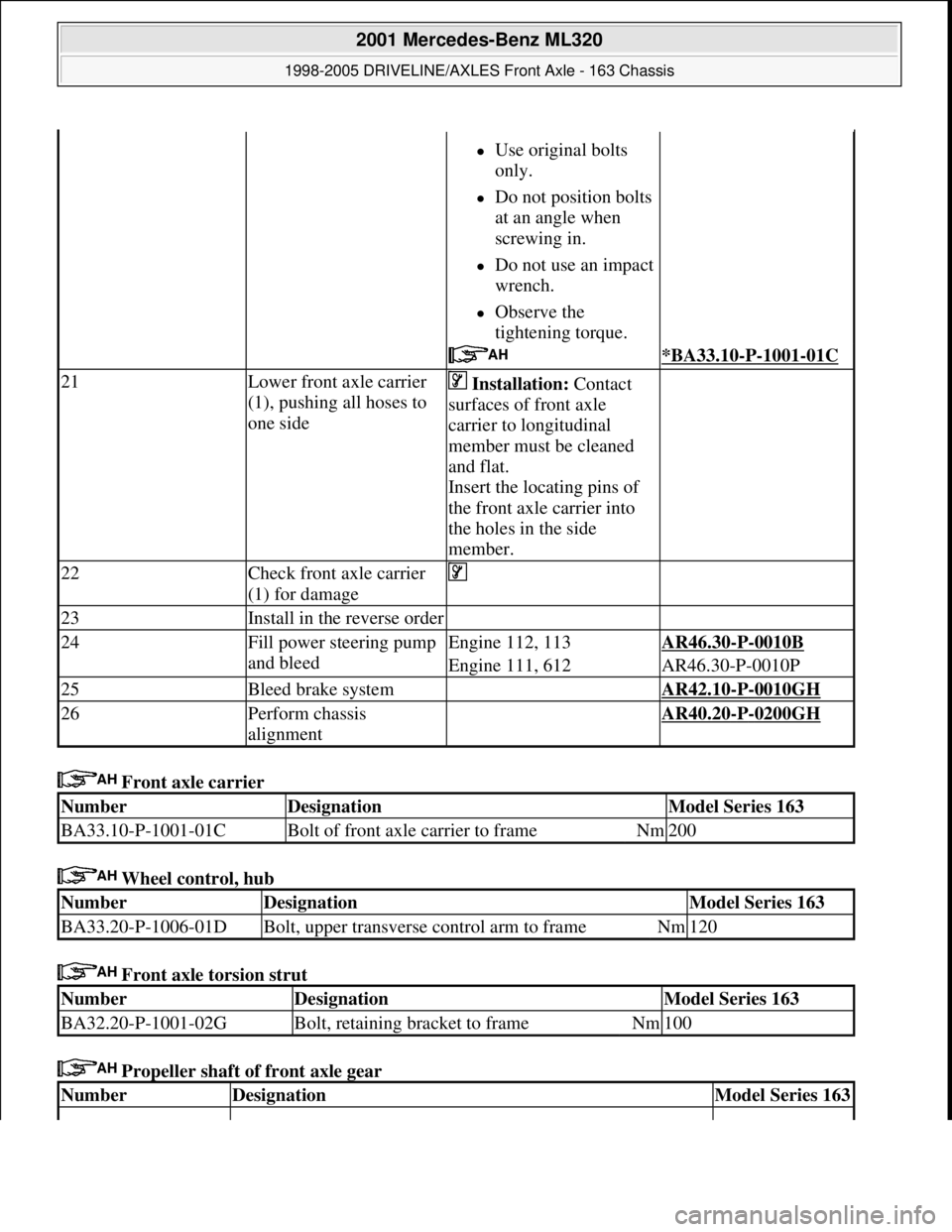
Front axle carrier
Wheel control, hub
Front axle torsion strut
Propeller shaft of front axle gear
Use original bolts
only.
Do not position bolts
at an angle when
screwing in.
Do not use an impact
wrench.
Observe the
tightening torque.
*BA33.10-P-1001-01C
21Lower front axle carrier
(1), pushing all hoses to
one side Installation: Contact
surfaces of front axle
carrier to longitudinal
member must be cleaned
and flat.
Insert the locating pins of
the front axle carrier into
the holes in the side
member.
22Check front axle carrier
(1) for damage
23Install in the reverse order
24Fill power steering pump
and bleedEngine 112, 113AR46.30-P-0010B
Engine 111, 612AR46.30-P-0010P
25Bleed brake system AR42.10-P-0010GH
26Perform chassis
alignment AR40.20-P-0200GH
NumberDesignationModel Series 163
BA33.10-P-1001-01CBolt of front axle carrier to frameNm200
NumberDesignationModel Series 163
BA33.20-P-1006-01DBolt, upper transverse control arm to frameNm120
NumberDesignationModel Series 163
BA32.20-P-1001-02GBolt, retaining bracket to frameNm100
NumberDesignationModel Series 163
2001 Mercedes-Benz ML320
1998-2005 DRIVELINE/AXLES Front Axle - 163 Chassis
me
Saturday, October 02, 2010 3:38:21 PMPage 7 © 2006 Mitchell Repair Information Company, LLC.
Page 2845 of 4133
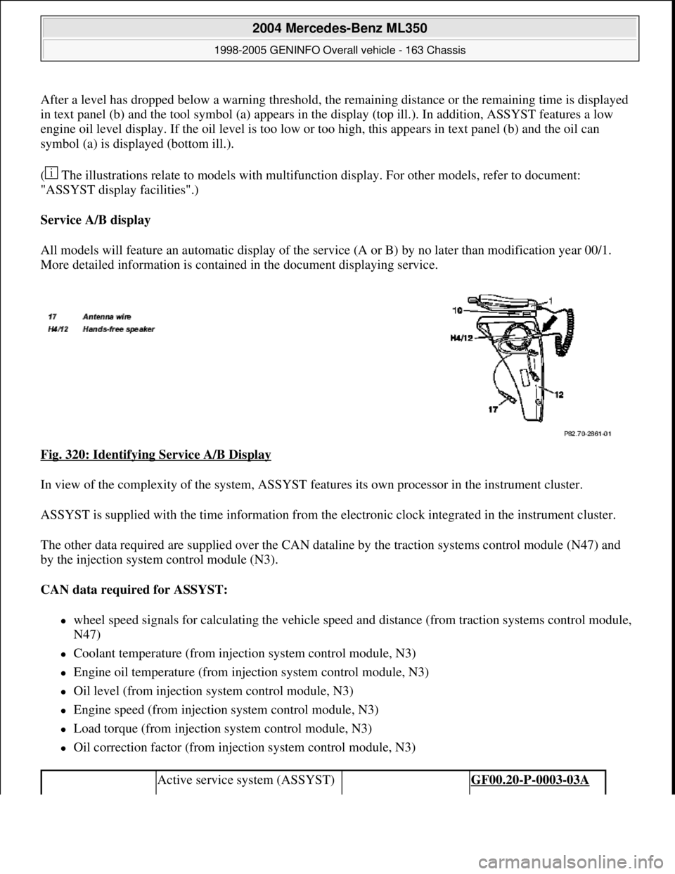
After a level has dropped below a warning threshold, the remaining distance or the remaining time is displayed
in text panel (b) and the tool symbol (a) appears in the display (top ill.). In addition, ASSYST features a low
engine oil level display. If the oil level is too low or too high, this appears in text panel (b) and the oil can
symbol (a) is displayed (bottom ill.).
( The illustrations relate to models with multifunction display. For other models, refer to document:
"ASSYST display facilities".)
Service A/B display
All models will feature an automatic display of the service (A or B) by no later than modification year 00/1.
More detailed information is contained in the document displaying service.
Fig. 320: Identifying Service A/B Display
In view of the complexity of the system, ASSYST features its own processor in the instrument cluster.
ASSYST is supplied with the time information from the electronic clock integrated in the instrument cluster.
The other data required are supplied over the CAN dataline by the traction systems control module (N47) and
by the injection system control module (N3).
CAN data required for ASSYST:
wheel speed signals for calculating the vehicle speed and distance (from traction systems control module,
N47)
Coolant temperature (from injection system control module, N3)
Engine oil temperature (from injection system control module, N3)
Oil level (from injection system control module, N3)
Engine speed (from injection system control module, N3)
Load torque (from injection system control module, N3)
Oil correction factor (from injection system control module, N3)
Active service system (ASSYST) GF00.20-P-0003-03A
2004 Mercedes-Benz ML350
1998-2005 GENINFO Overall vehicle - 163 Chassis
me
Saturday, October 02, 2010 3:47:47 PMPage 200 © 2006 Mitchell Repair Information Company, LLC.
Page 3153 of 4133
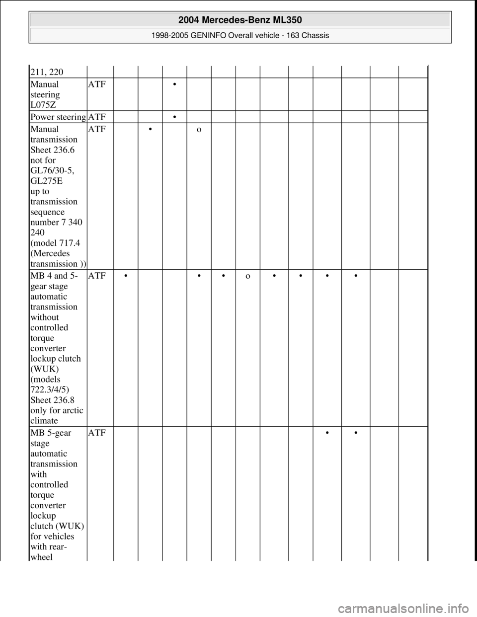
211, 220
Manual
steering
L075ZATF •
Power steeringATF •
Manual
transmission
Sheet 236.6
not for
GL76/30-5,
GL275E
up to
transmission
sequence
number 7 340
240
(model 717.4
(Mercedes
transmission ))ATF • o
MB 4 and 5-
gear stage
automatic
transmission
without
controlled
torque
converter
lockup clutch
(WUK)
(models
722.3/4/5)
Sheet 236.8
only for arctic
climateATF• ••o••••
MB 5-gear
stage
automatic
transmission
with
controlled
torque
converter
lockup
clutch (WUK)
for vehicles
with rear-
wheel ATF ••
2004 Mercedes-Benz ML350
1998-2005 GENINFO Overall vehicle - 163 Chassis
me
Saturday, October 02, 2010 3:47:56 PMPage 508 © 2006 Mitchell Repair Information Company, LLC.