1997 MERCEDES-BENZ ML320 garage door opener
[x] Cancel search: garage door openerPage 3526 of 4133
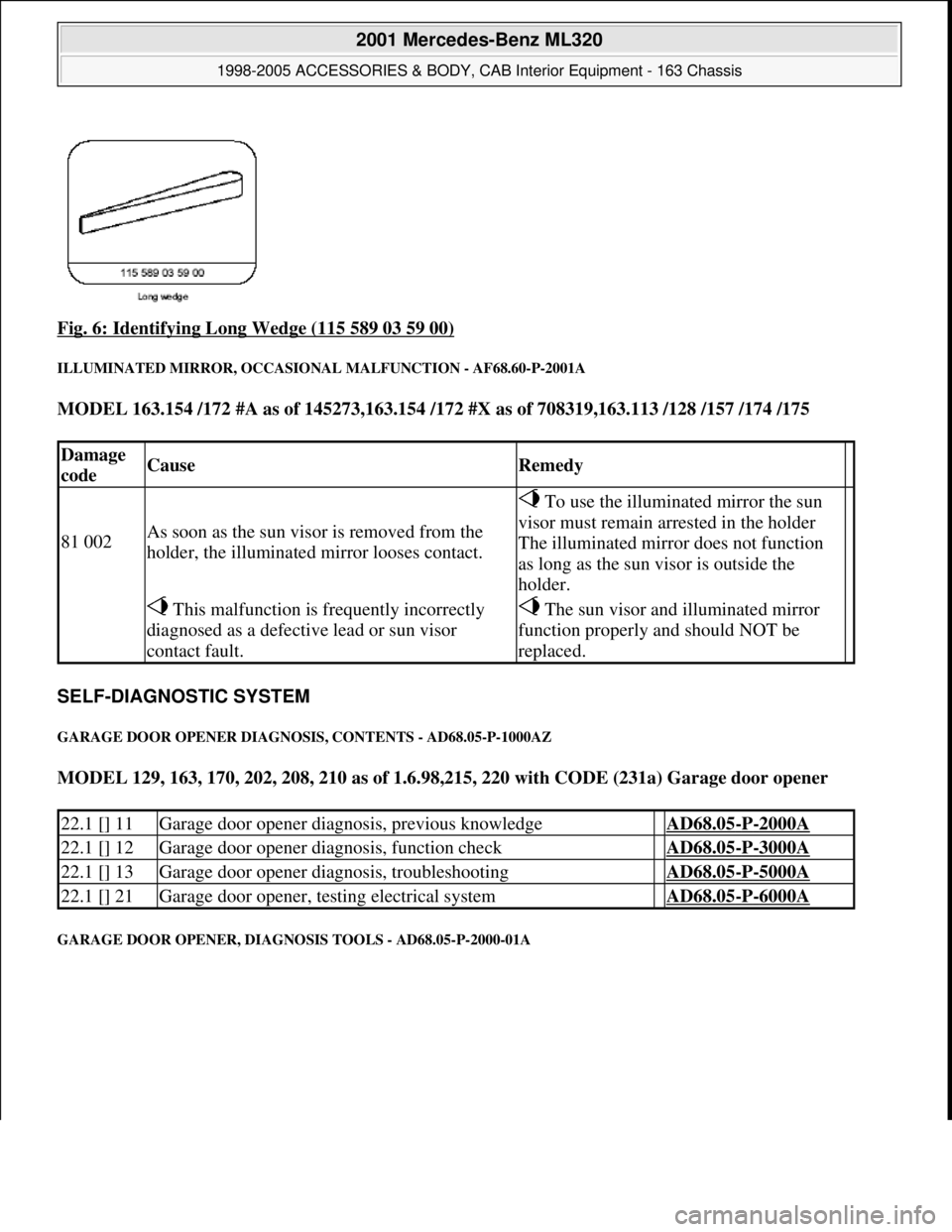
Fig. 6: Identifying Long Wedge (115 589 03 59 00)
ILLUMINATED MIRROR, OCCASIONAL MALFUNCTION - AF68.60-P-2001A
MODEL 163.154 /172 #A as of 145273,163.154 /172 #X as of 708319,163.113 /128 /157 /174 /175
SELF-DIAGNOSTIC SYSTEM
GARAGE DOOR OPENER DIAGNOSIS, CONTENTS - AD68.05-P-1000AZ
MODEL 129, 163, 170, 202, 208, 210 as of 1.6.98,215, 220 with CODE (231a) Garage door opener
GARAGE DOOR OPENER, DIAGNOSIS TOOLS - AD68.05-P-2000-01A
Damage
codeCauseRemedy
81 002As soon as the sun visor is removed from the
holder, the illuminated mirror looses contact.
To use the illuminated mirror the sun
visor must remain arrested in the holder
The illuminated mirror does not function
as long as the sun visor is outside the
holder.
This malfunction is frequently incorrectly
diagnosed as a defective lead or sun visor
contact fault. The sun visor and illuminated mirror
function properly and should NOT be
replaced.
22.1 [] 11Garage door opener diagnosis, previous knowledge AD68.05-P-2000A
22.1 [] 12Garage door opener diagnosis, function check AD68.05-P-3000A
22.1 [] 13Garage door opener diagnosis, troubleshooting AD68.05-P-5000A
22.1 [] 21Garage door opener, testing electrical system AD68.05-P-6000A
2001 Mercedes-Benz ML320
1998-2005 ACCESSORIES & BODY, CAB Interior Equipment - 163 Chassis
me
Saturday, October 02, 2010 3:35:21 PMPage 8 © 2006 Mitchell Repair Information Company, LLC.
Page 3527 of 4133
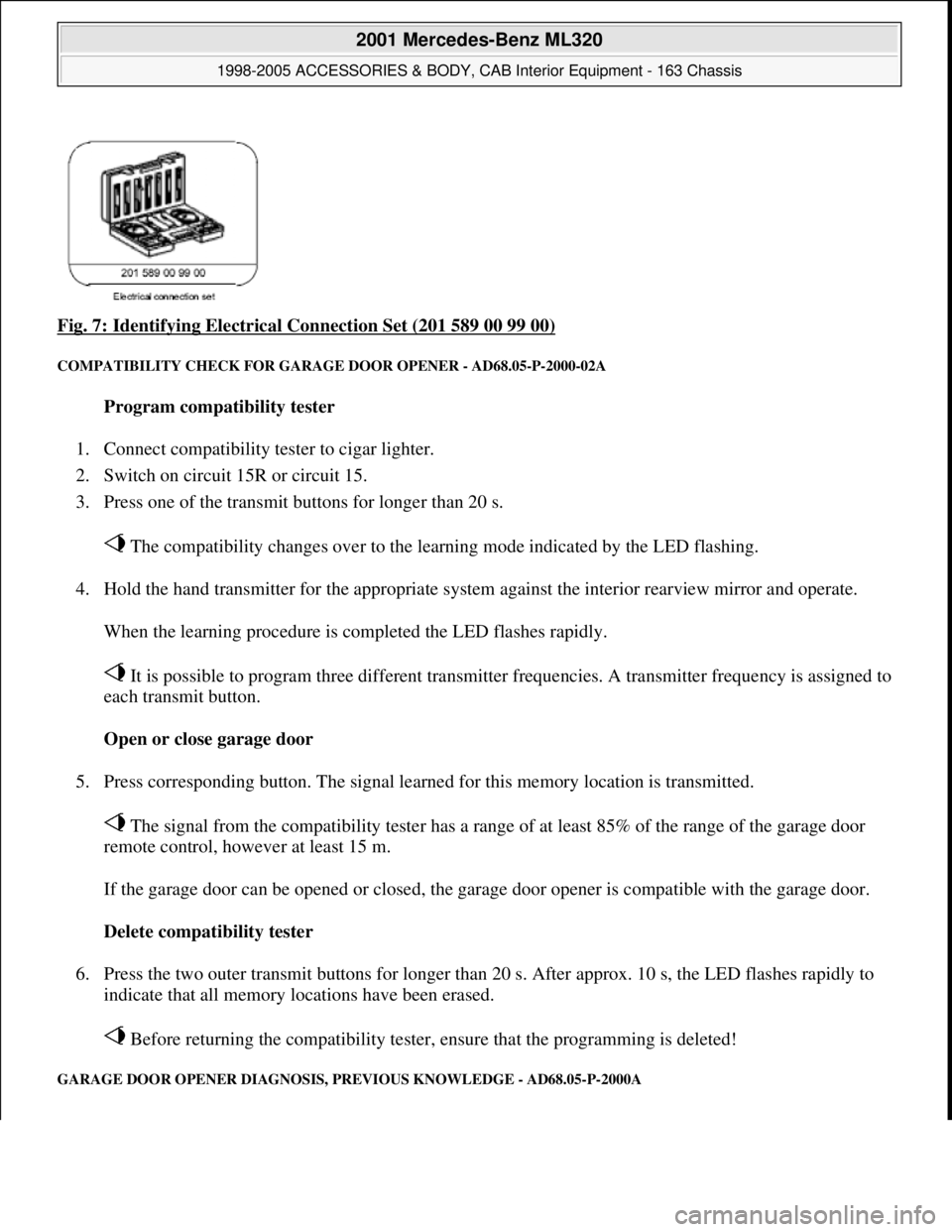
Fig. 7: Identifying Electrical Connection Set (201 589 00 99 00)
COMPATIBILITY CHECK FOR GARAGE DOOR OPENER - AD68.05-P-2000-02A
Program compatibility tester
1. Connect compatibility tester to cigar lighter.
2. Switch on circuit 15R or circuit 15.
3. Press one of the transmit buttons for longer than 20 s.
The compatibility changes over to the learning mode indicated by the LED flashing.
4. Hold the hand transmitter for the appropriate system against the interior rearview mirror and operate.
When the learning procedure is completed the LED flashes rapidly.
It is possible to program three different transmitter frequencies. A transmitter frequency is assigned to
each transmit button.
Open or close garage door
5. Press corresponding button. The signal learned for this memory location is transmitted.
The signal from the compatibility tester has a range of at least 85% of the range of the garage door
remote control, however at least 15 m.
If the garage door can be opened or closed, the garage door opener is compatible with the garage door.
Delete compatibility tester
6. Press the two outer transmit buttons for longer than 20 s. After approx. 10 s, the LED flashes rapidly to
indicate that all memory locations have been erased.
Before returning the compatibility tester, ensure that the programming is deleted!
GARAGE DOOR OPENER DIAGNOSIS, PREVIOUS KNOWLEDGE - AD68.05-P-2000A
2001 Mercedes-Benz ML320
1998-2005 ACCESSORIES & BODY, CAB Interior Equipment - 163 Chassis
me
Saturday, October 02, 2010 3:35:21 PMPage 9 © 2006 Mitchell Repair Information Company, LLC.
Page 3528 of 4133
MODEL 129, 163, 170, 202, 208, 210 as of 1.6.98,215, 220 with CODE (231a) Garage door opener
GARAGE DOOR OPENER DIAGNOSIS, FUNCTION CHECK - AD68.05-P-3000A
MODEL 129, 163, 170, 202, 208, 210 as of 1.6.98,215, 220 with CODE (231a) Garage door opener
GARAGE DOOR OPENER DIAGNOSIS, TROUBLE-SHOOTING - AD68.05-P-5000A
MODELS 129, 163, 170, 202, 208, 210 as of 1.6.98,215, 220 with CODE (231a) Garage door opener
Garage door opener locationModels 129, 202, 208, 210, 215, 220GF68.05-P-1100-01A
Model 170GF68.05-P-1100-01B
Model 163GF68.05-P-1100-01C
Electrical wiring diagramsModel 163PE68.00-P-1100D
Model 170PE68.00-P-1100C
Models 202, 208PE68.00-P-1100B
Model 210PE68.00-P-1100A
Model 220PE68.00-P-1100SA
Model 129, volume 2, FG 68
Connection and use of test equipment AD00.00-P-1000AZ
Diagnostic tools, garage door opener AD68.05-P-2000-01A
Compatibility test for garage door opener AD68.05-P-2000-02A
Garage door opener diagnosis, previous knowledge AD68.05-P-
2000A
Key to diagnostic symbols AD00.00-P-
2001A
Fuses in order
Battery voltage 11-14V
Ignition: ON
Function check
Scope of test Operation / requirement Specified value Possible
cause / remedy
1
Transmitting
push-button
The desired transmitting push-button is programmed.
The vehicle is inside the garage door range.
The garage door opener signal has a range of at least
85% of the range of the garage door hand transmitter or
15m.
Press programmed transmitting push-button.
Garage door is
activated.AD68.05-P-
5000A
Garage door opener
diagnosis, previous
knowledge
AD68.05-P-2000A
2001 Mercedes-Benz ML320
1998-2005 ACCESSORIES & BODY, CAB Interior Equipment - 163 Chassis
me
Saturday, October 02, 2010 3:35:21 PMPage 10 © 2006 Mitchell Repair Information Company, LLC.
Page 3529 of 4133
Fuses in order.
Battery voltage
11-14 V
Ignition: ON
Troubleshooting
Complaint Possible cause Note Remedy
The garage door
cannot be
activated with the
garage door
opener installed
in the vehicle.
The garage door opener
has not been
programmed correctly.
GF68.05-P-0001A
The garage door is
defective
Check garage door: Activate
the garage door with the
hand transmitter. If the
garage door cannot be
opened and closed with the
hand transmitter, the garage
door has a mechanical or
electrical defect.
The garage door's
receiver and the garage
door opener installed in
the vehicle are not
compatible.
A list of compatible garage
doors is included in the
passenger car sales manualIf the used garage door is not
listed check compatibility
with compatibility tester.
Compatibility check of
electrical system for garage
door opener Models 129, 170,
202, 208, 210 as of 1.6.98, 163
as of 1.9.01, 215, 220 with
CODE (231a) garage door
opener Compatibility check for
garage door opener.
AD68.05-P-6000-02A
AD68.05
-P-2000-02A
Voltage supply to
garage door opener
interrupted.Model 208 as of 1.6.98, except
CODE (249a)
Automatic dimming inside
rearview mirror
AD68.05-P-6000-01A
Model 202 as of 1.6.98, Model
210 as of 1.6.98, except CODE
(249a)
Automatic dimming inside
rearview mirror
AD68.05-P-6000-01C
Model 202 as of 1.6.98, Model
208 as of 1.6.98, Model 210 as
of 1.6.98, with CODE (249a) AD68.05-P-6000-01G
2001 Mercedes-Benz ML320
1998-2005 ACCESSORIES & BODY, CAB Interior Equipment - 163 Chassis
me
Saturday, October 02, 2010 3:35:21 PMPage 11 © 2006 Mitchell Repair Information Company, LLC.
Page 3530 of 4133
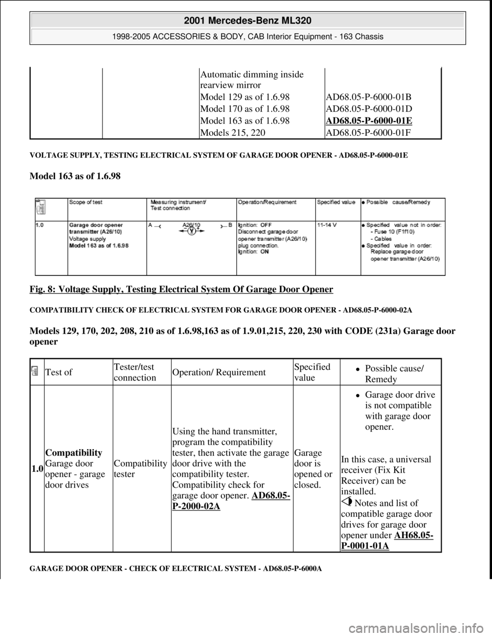
VOLTAGE SUPPLY, TESTING ELECTRICAL SYSTEM OF GARAGE DOOR OPENER - AD68.05-P-6000-01E
Model 163 as of 1.6.98
Fig. 8: Voltage Supply, Testing Electrical System Of Garage Door Opener
COMPATIBILITY CHECK OF ELECTRICAL SYSTEM FOR GARAGE DOOR OPENER - AD68.05-P-6000-02A
Models 129, 170, 202, 208, 210 as of 1.6.98,163 as of 1.9.01,215, 220, 230 with CODE (231a) Garage door
opener
GARAGE DOOR OPENER - CHECK OF ELECTRICAL SYSTEM - AD68.05-P-6000A
Automatic dimming inside
rearview mirror
Model 129 as of 1.6.98AD68.05-P-6000-01B
Model 170 as of 1.6.98AD68.05-P-6000-01D
Model 163 as of 1.6.98AD68.05-P-6000-01E
Models 215, 220AD68.05-P-6000-01F
Test ofTester/test
connectionOperation/ RequirementSpecified
valuePossible cause/
Remedy
1.0
Compatibility
Garage door
opener - garage
door drives
Compatibility
tester
Using the hand transmitter,
program the compatibility
tester, then activate the garage
door drive with the
compatibility tester.
Compatibility check for
garage door opener. AD68.05
-
P-2000-02A
Garage
door is
opened or
closed.
Garage door drive
is not compatible
with garage door
opener.
In this case, a universal
receiver (Fix Kit
Receiver) can be
installed.
Notes and list of
compatible garage door
drives for garage door
opener under AH68.05
-
P-0001-01A
2001 Mercedes-Benz ML320
1998-2005 ACCESSORIES & BODY, CAB Interior Equipment - 163 Chassis
me
Saturday, October 02, 2010 3:35:21 PMPage 12 © 2006 Mitchell Repair Information Company, LLC.
Page 3531 of 4133
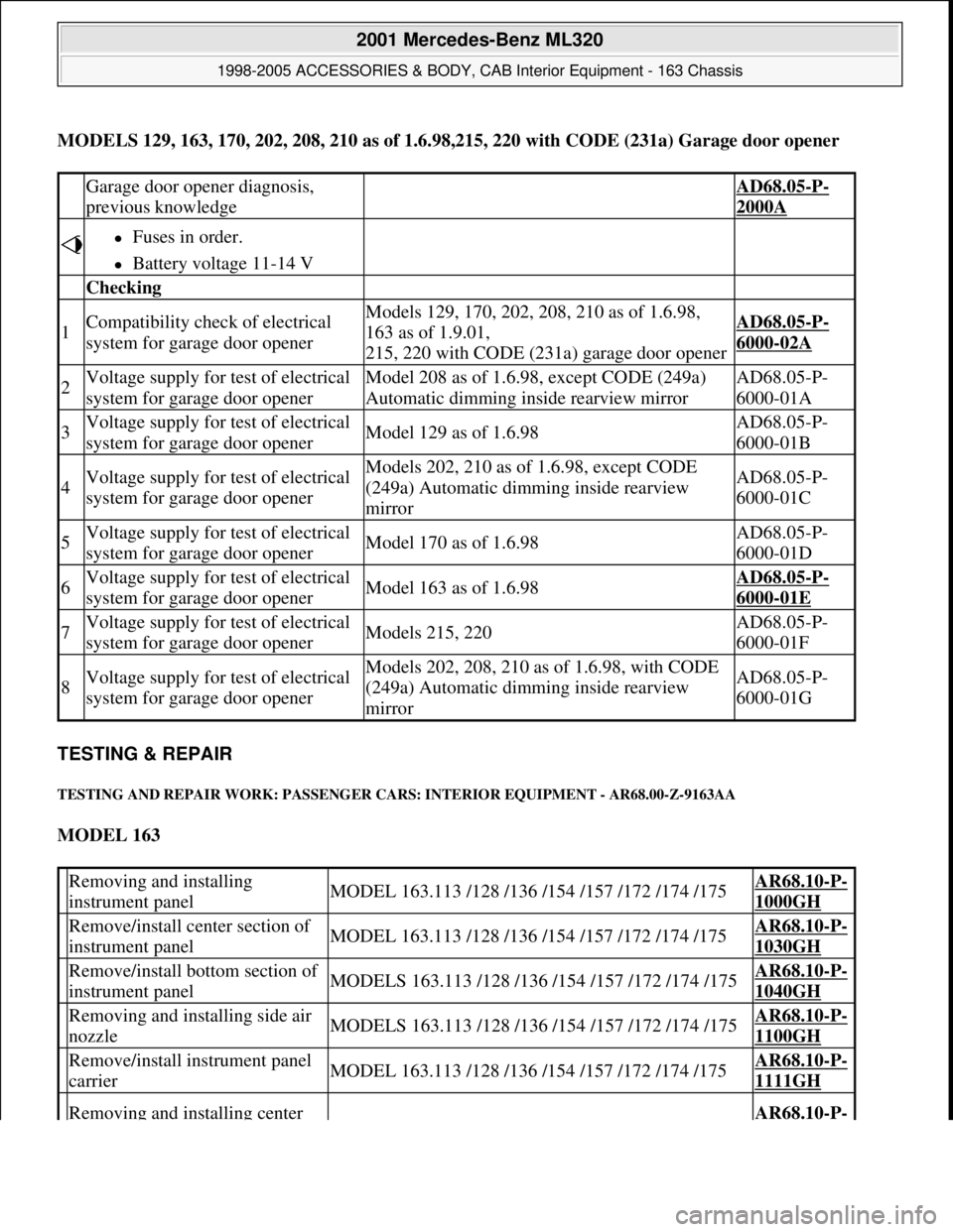
MODELS 129, 163, 170, 202, 208, 210 as of 1.6.98,215, 220 with CODE (231a) Garage door opener
TESTING & REPAIR
TESTING AND REPAIR WORK: PASSENGER CARS: INTERIOR EQUIPMENT - AR68.00-Z-9163AA
MODEL 163
Garage door opener diagnosis,
previous knowledge AD68.05-P-
2000A
Fuses in order.
Battery voltage 11-14 V
Checking
1Compatibility check of electrical
system for garage door openerModels 129, 170, 202, 208, 210 as of 1.6.98,
163 as of 1.9.01,
215, 220 with CODE (231a) garage door openerAD68.05-P-
6000-02A
2Voltage supply for test of electrical
system for garage door openerModel 208 as of 1.6.98, except CODE (249a)
Automatic dimming inside rearview mirrorAD68.05-P-
6000-01A
3Voltage supply for test of electrical
system for garage door openerModel 129 as of 1.6.98AD68.05-P-
6000-01B
4Voltage supply for test of electrical
system for garage door openerModels 202, 210 as of 1.6.98, except CODE
(249a) Automatic dimming inside rearview
mirrorAD68.05-P-
6000-01C
5Voltage supply for test of electrical
system for garage door openerModel 170 as of 1.6.98AD68.05-P-
6000-01D
6Voltage supply for test of electrical
system for garage door openerModel 163 as of 1.6.98AD68.05-P-
6000-01E
7Voltage supply for test of electrical
system for garage door openerModels 215, 220AD68.05-P-
6000-01F
8Voltage supply for test of electrical
system for garage door openerModels 202, 208, 210 as of 1.6.98, with CODE
(249a) Automatic dimming inside rearview
mirrorAD68.05-P-
6000-01G
Removing and installing
instrument panelMODEL 163.113 /128 /136 /154 /157 /172 /174 /175AR68.10-P-
1000GH
Remove/install center section of
instrument panelMODEL 163.113 /128 /136 /154 /157 /172 /174 /175AR68.10-P-
1030GH
Remove/install bottom section of
instrument panelMODELS 163.113 /128 /136 /154 /157 /172 /174 /175AR68.10-P-
1040GH
Removing and installing side air
nozzleMODELS 163.113 /128 /136 /154 /157 /172 /174 /175AR68.10-P-
1100GH
Remove/install instrument panel
carrierMODEL 163.113 /128 /136 /154 /157 /172 /174 /175AR68.10-P-
1111GH
Removing and installing center AR68.10-P-
2001 Mercedes-Benz ML320
1998-2005 ACCESSORIES & BODY, CAB Interior Equipment - 163 Chassis
me
Saturday, October 02, 2010 3:35:21 PMPage 13 © 2006 Mitchell Repair Information Company, LLC.
Page 3736 of 4133
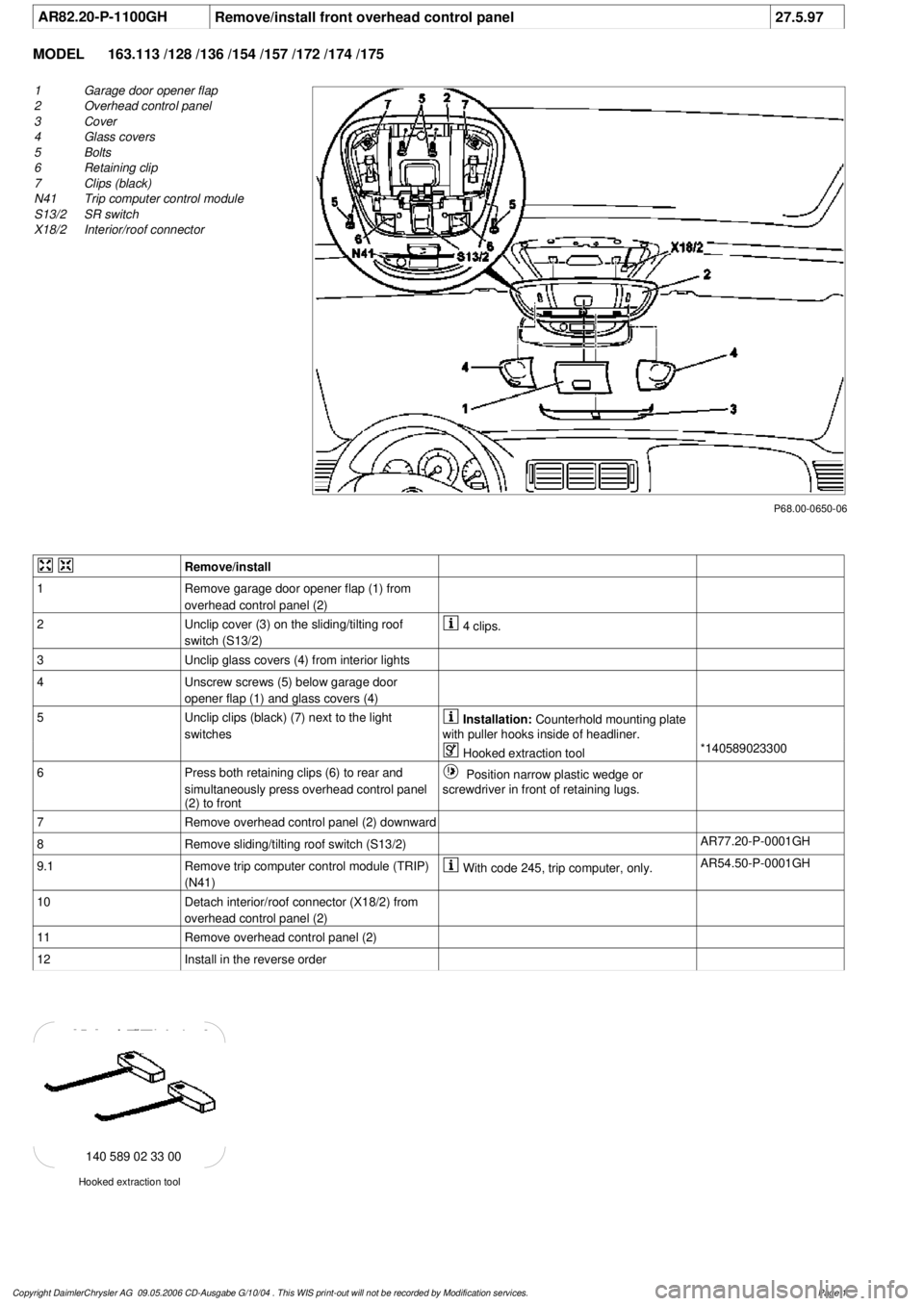
AR82.20-P-1100GH
Remove/install front overhead control panel
27.5.97
MODEL
163.113 /128 /136 /154 /157 /172 /174 /175
P68.00-0650-06
1
Garage door opener flap
2
Overhead control panel
3
Cover
4
Glass covers
5
Bolts
6
Retaining clip
7
Clips (black)
N41
Trip computer control module
S13/2
SR switch
X18/2
Interior/roof connector
Remove/install
1
Remove garage door opener flap (1) from
overhead control panel (2)
2
Unclip cover (3) on the sliding/tilting roof
switch (S13/2)
4 clips.
3
Unclip glass covers (4) from interior lights
4
Unscrew screws (5) below garage door
opener flap (1) and glass covers (4)
5
Unclip clips (black) (7) next to the light
switches
Installation:
Counterhold mounting plate
with puller hooks inside of headliner.
Hooked extraction tool
*140589023300
6
Press both retaining clips (6) to rear and
simultaneously press overhead control panel
(2) to front
Position narrow plastic wedge or
screwdriver in front of retaining lugs.
7
Remove overhead control panel (2) downward
8
Remove sliding/tilting roof switch (S13/2)
AR77.20-P-0001GH
9.1
Remove trip computer control module (TRIP)
(N41)
With code 245, trip computer, only.
AR54.50-P-0001GH
10
Detach interior/roof connector (X18/2) from
overhead control panel (2)
11
Remove overhead control panel (2)
12
Install in the reverse order
Hooked extraction tool
140 589 02 33 00
Copyright DaimlerChrysler AG 09.05.2006 CD-Ausgabe G/10/04 . This WIS print-out will not be recorde
d by Modification services.
Page 1