1997 MERCEDES-BENZ ML320 fuse
[x] Cancel search: fusePage 1516 of 4133
XENON HEADLAMPS, FUNCTION - GF82.10-P-2007-01GHA
The lighting technology, known as bi-xenon 70 , is located in the outer headlamps.
When the low beam lamps are switched on the xenon headlamp control module (E1 n1, E2n1) activates the
xenon headlamp control module and ignition module (E1n2, E2n2) via the control voltage within a few
milliseconds.
A high-voltage surge from the ignition device ignites the xenon lamps, and in doing so an electric arc is formed
between the electrodes. When an arc of sufficient stability is detected, the control electronics of the control
module (E1 n1, E2n1) switches over to power-limiting mode.
The light generated previously in a gas discharge lamp (D2S lamp) is not reflected in bi-xenon 70 headlamps,
but instead it is sent directly through a lens optical system with a lens diameter of 70 mm.
Using the mask (B), which is positioned between the gas discharge lamp and the lens optical system, the beam
of light is partially masked for the low beam so that oncoming traffic is not blinded.
For the high beam, the mask (B) is electro-mechanically folded to the side using the solenoid (M).
If the solenoid (M) should fail or a supply line breaks, the mask (B) remains mechanically held in the low
beam position, always between the gas discharge lamp and the lens optical system.
In order to make the extremely bright light more acceptable to other road users, the lens aperture area with its
dotted characteristic is optically enlarged.
This is possible on account of the specially formed areas which surround the lens. In addition, the light can pass
through a number of chrome-plated strips from the rear. A portion of the diffused light is intercepted by the
lower section of the surface area and reflected to the upper section of the chrome-plated longitudinal strips.
For technical reasons the xenon lamp has a timed startup characteristic. After switch on, 50 % of the luminosity
is reached within 1 to 2 seconds and full luminosity is achieved after another approx. 30 seconds.
XENON HEADLAMP, LOCATION/DESIGN/FUNCTION - GF82.10-P-2007GH
MODELS 163.113 /136 /154 /172 up to 31.08.01 with CODE (612b) xenon headlamp unit with CODE
(U47) conversion package
MODELS 163.174 up to 31.08.01, 163.113 /128 /136 /154 /172 as of 01.09.01
Design:
From model
year 2002 (as of 1.9.01) the xenon headlamps are installed as standard.
2001 Mercedes-Benz ML320
1998-2005 ACCESSORIES & BODY, CAB Electrical System - Body - 163 Chassis
me
Saturday, October 02, 2010 3:30:04 PMPage 21 © 2006 Mitchell Repair Information Company, LLC.
Page 1683 of 4133
MODEL 163
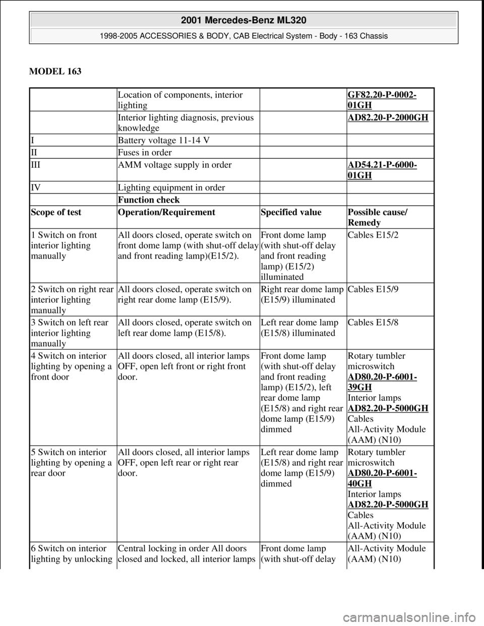
Location of components, interior
lighting GF82.20-P-0002-
01GH
Interior lighting diagnosis, previous
knowledge AD82.20-P-2000GH
IBattery voltage 11-14 V
IIFuses in order
IIIAMM voltage supply in order AD54.21-P-6000-
01GH
IVLighting equipment in order
Function check
Scope of test Operation/Requirement Specified value Possible cause/
Remedy
1 Switch on front
interior lighting
manuallyAll doors closed, operate switch on
front dome lamp (with shut-off delay
and front reading lamp)(E15/2).Front dome lamp
(with shut-off delay
and front reading
lamp) (E15/2)
illuminatedCables E15/2
2 Switch on right rear
interior lighting
manuallyAll doors closed, operate switch on
right rear dome lamp (E15/9).Right rear dome lamp
(E15/9) illuminatedCables E15/9
3 Switch on left rear
interior lighting
manuallyAll doors closed, operate switch on
left rear dome lamp (E15/8).Left rear dome lamp
(E15/8) illuminatedCables E15/8
4 Switch on interior
lighting by opening a
front doorAll doors closed, all interior lamps
OFF, open left front or right front
door.Front dome lamp
(with shut-off delay
and front reading
lamp) (E15/2), left
rear dome lamp
(E15/8) and right rear
dome lamp (E15/9)
dimmedRotary tumbler
microswitch
AD80.20
-P-6001-
39GH
Interior lamps
AD82.20
-P-5000GH
Cables
All-Activity Module
(AAM) (N10)
5 Switch on interior
lighting by opening a
rear doorAll doors closed, all interior lamps
OFF, open left rear or right rear
door.Left rear dome lamp
(E15/8) and right rear
dome lamp (E15/9)
dimmedRotary tumbler
microswitch
AD80.20
-P-6001-
40GH
Interior lamps
AD82.20
-P-5000GH
Cables
All-Activity Module
(AAM) (N10)
6 Switch on interior
lighting by unlocking Central locking in order All doors
closed and locked, all interior lamps Front dome lamp
(with shut-off delay All-Activity Module
(AAM) (N10)
2001 Mercedes-Benz ML320
1998-2005 ACCESSORIES & BODY, CAB Electrical System - Body - 163 Chassis
me
Saturday, October 02, 2010 3:30:07 PMPage 188 © 2006 Mitchell Repair Information Company, LLC.
Page 1684 of 4133
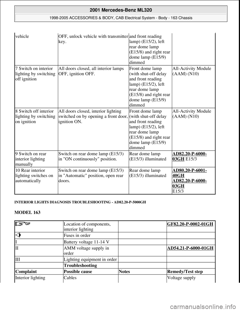
INTERIOR LIGHTS DIAGNOSIS TROUBLESHOOTING - AD82.20-P-5000GH
MODEL 163
vehicleOFF, unlock vehicle with transmitter
key.and front reading
lamp) (E15/2), left
rear dome lamp
(E15/8) and right rear
dome lamp (E15/9)
dimmed
7 Switch on interior
lighting by switching
off ignitionAll doors closed, all interior lamps
OFF, ignition OFF.Front dome lamp
(with shut-off delay
and front reading
lamp) (E15/2), left
rear dome lamp
(E15/8) and right rear
dome lamp (E15/9)
dimmedAll-Activity Module
(AAM) (N10)
8 Switch off interior
lighting by switching
on ignitionAll doors closed, interior lighting
switched on by opening a front door,
ignition ON.Front dome lamp
(with shut-off delay
and front reading
lamp) (E15/2), left
rear dome lamp
(E15/8) and right rear
dome lamp (E15/9)
dimmedAll-Activity Module
(AAM) (N10)
9 Switch on rear
interior lighting
manuallySwitch on rear dome lamp (E15/3)
in "ON continuously" position.Rear dome lamp
(E15/3) illuminatedAD82.20-P-6000-
03GH E15/3
10 Rear interior
lighting switches on
automaticallySwitch on rear dome lamp (E15/3)
in "Automatic" position, open rear
doors.Rear dome lamp
(E15/3) illuminatedAD80.20-P-6001-
40GH
AD82.20
-P-6000-
03GH
E15/3
Location of components,
interior lighting GF82.20-P-0002-01GH
Fuses in order
IBattery voltage 11-14 V
IIAMM voltage supply in
order AD54.21-P-6000-01GH
IIILighting equipment in order
Troubleshooting
Complaint Possible cause Notes Remedy/Test step
Interior lighting Cables Voltage supply
2001 Mercedes-Benz ML320
1998-2005 ACCESSORIES & BODY, CAB Electrical System - Body - 163 Chassis
me
Saturday, October 02, 2010 3:30:07 PMPage 189 © 2006 Mitchell Repair Information Company, LLC.
Page 1687 of 4133
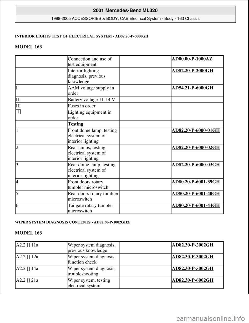
INTERIOR LIGHTS TEST OF ELECTRICAL SYSTEM - AD82.20-P-6000GH
MODEL 163
WIPER SYSTEM DIAGNOSIS CONTENTS - AD82.30-P-1002GHZ
MODEL 163
Connection and use of
test equipment AD00.00-P-1000AZ
Interior lighting
diagnosis, previous
knowledge AD82.20-P-2000GH
IAAM voltage supply in
order AD54.21-P-6000GH
IIBattery voltage 11-14 V
IIIFuses in order
Lighting equipment in
order
Testing
1Front dome lamp, testing
electrical system of
interior lighting AD82.20-P-6000-01GH
2Rear lamps, testing
electrical system of
interior lighting AD82.20-P-6000-02GH
3Rear dome lamp, testing
electrical system of
interior lighting AD82.20-P-6000-03GH
4Front doors rotary
tumbler microswitch AD80.20-P-6001-39GH
5Rear doors rotary tumbler
microswitch AD80.20-P-6001-40GH
6Tailgate rotary tumbler
microswitch AD80.20-P-6001-44GH
A2.2 [] 11aWiper system diagnosis,
previous knowledge AD82.30-P-2002GH
A2.2 [] 12aWiper system diagnosis,
function check AD82.30-P-3002GH
A2.2 [] 14aWiper system diagnosis,
troubleshooting AD82.30-P-5002GH
A2.2 [] 21aWiper system, testing
electrical system AD82.30-P-6002GH
2001 Mercedes-Benz ML320
1998-2005 ACCESSORIES & BODY, CAB Electrical System - Body - 163 Chassis
me
Saturday, October 02, 2010 3:30:07 PMPage 192 © 2006 Mitchell Repair Information Company, LLC.
Page 1688 of 4133
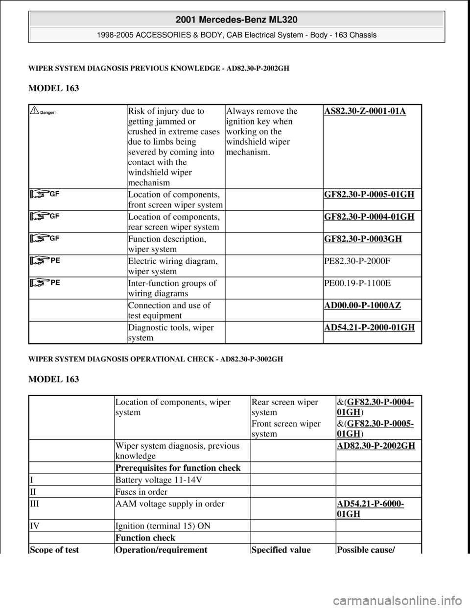
WIPER SYSTEM DIAGNOSIS PREVIOUS KNOWLEDGE - AD82.30-P-2002GH
MODEL 163
WIPER SYSTEM DIAGNOSIS OPERATIONAL CHECK - AD82.30-P-3002GH
MODEL 163
Risk of injury due to
getting jammed or
crushed in extreme cases
due to limbs being
severed by coming into
contact with the
windshield wiper
mechanismAlways remove the
ignition key when
working on the
windshield wiper
mechanism.AS82.30-Z-0001-01A
Location of components,
front screen wiper system GF82.30-P-0005-01GH
Location of components,
rear screen wiper system GF82.30-P-0004-01GH
Function description,
wiper system GF82.30-P-0003GH
Electric wiring diagram,
wiper system PE82.30-P-2000F
Inter-function groups of
wiring diagrams PE00.19-P-1100E
Connection and use of
test equipment AD00.00-P-1000AZ
Diagnostic tools, wiper
system AD54.21-P-2000-01GH
Location of components, wiper
systemRear screen wiper
system&(GF82.30-P-0004-
01GH)
Front screen wiper
system&(GF82.30-P-0005-
01GH)
Wiper system diagnosis, previous
knowledge AD82.30-P-2002GH
Prerequisites for function check
IBattery voltage 11-14V
IIFuses in order
IIIAAM voltage supply in order AD54.21-P-6000-
01GH
IVIgnition (terminal 15) ON
Function check
Scope of test Operation/requirement Specified value Possible cause/
2001 Mercedes-Benz ML320
1998-2005 ACCESSORIES & BODY, CAB Electrical System - Body - 163 Chassis
me
Saturday, October 02, 2010 3:30:07 PMPage 193 © 2006 Mitchell Repair Information Company, LLC.
Page 1690 of 4133
Location of components,
wiper systemFront screen&(GF82.30-P-0005-
01GH)
Rear screen&(GF82.30-P-0004-
01GH)
Battery voltage 11-14 V
Fuses in order
AAM voltage supply in
order AD54.21-P-6000-01GH
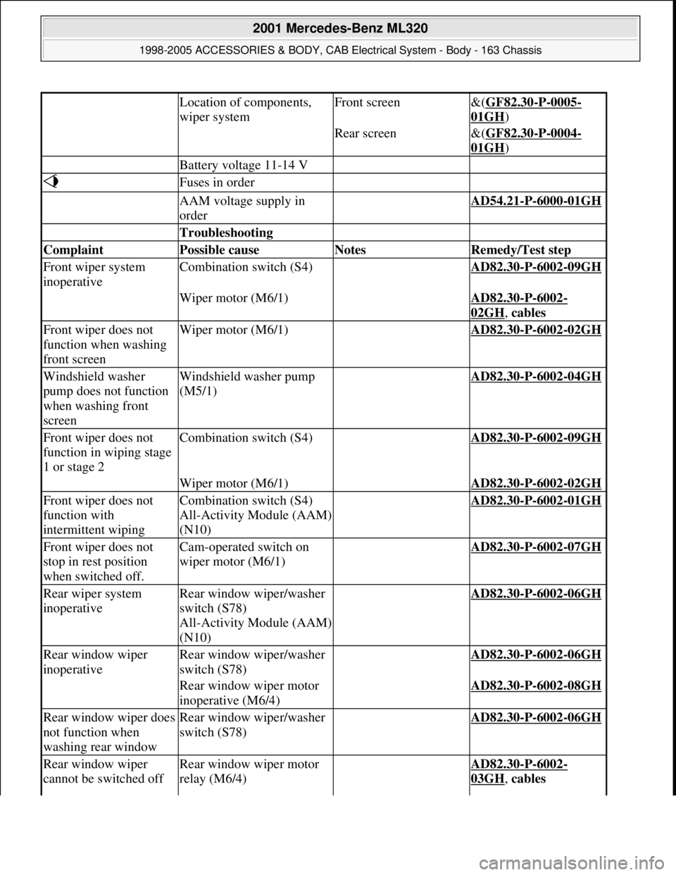
Troubleshooting
Complaint Possible cause Notes Remedy/Test step
Front wiper system
inoperativeCombination switch (S4) AD82.30-P-6002-09GH
Wiper motor (M6/1) AD82.30-P-6002-
02GH, cables
Front wiper does not
function when washing
front screenWiper motor (M6/1) AD82.30-P-6002-02GH
Windshield washer
pump does not function
when washing front
screenWindshield washer pump
(M5/1) AD82.30-P-6002-04GH
Front wiper does not
function in wiping stage
1 or stage 2Combination switch (S4) AD82.30-P-6002-09GH
Wiper motor (M6/1) AD82.30-P-6002-02GH
Front wiper does not
function with
intermittent wipingCombination switch (S4)
All-Activity Module (AAM)
(N10) AD82.30-P-6002-01GH
Front wiper does not
stop in rest position
when switched off.Cam-operated switch on
wiper motor (M6/1) AD82.30-P-6002-07GH
Rear wiper system
inoperativeRear window wiper/washer
switch (S78)
All-Activity Module (AAM)
(N10) AD82.30-P-6002-06GH
Rear window wiper
inoperativeRear window wiper/washer
switch (S78) AD82.30-P-6002-06GH
Rear window wiper motor
inoperative (M6/4) AD82.30-P-6002-08GH
Rear window wiper does
not function when
washing rear windowRear window wiper/washer
switch (S78) AD82.30-P-6002-06GH
Rear window wiper
cannot be switched offRear window wiper motor
relay (M6/4) AD82.30-P-6002-
03GH, cables
2001 Mercedes-Benz ML320
1998-2005 ACCESSORIES & BODY, CAB Electrical System - Body - 163 Chassis
me
Saturday, October 02, 2010 3:30:07 PMPage 195 © 2006 Mitchell Repair Information Company, LLC.
Page 1695 of 4133
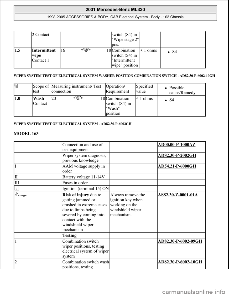
WIPER SYSTEM TEST OF ELECTRICAL SYSTEM WASHER POSITION COMBINATION SWITCH - AD82.30-P-6002-10GH
WIPER SYSTEM TEST OF ELECTRICAL SYSTEM - AD82.30-P-6002GH
MODEL 163
2 Contactswitch (S4) in
"Wipe stage 2"
pos.
1.5 Intermittent
wipe
Contact 116 18Combination
switch (S4) in
"Intermittent
wipe" position< 1 ohmsS4
Scope of
testMeasuring instrument/ Test
connectionOperation/
RequirementSpecified
valuePossible
cause/Remedy
1.0 Wash
Contact20 18Combination
switch (S4) in
"Wash"
position< 1 ohmsS4
Connection and use of
test equipment AD00.00-P-1000AZ
Wiper system diagnosis,
previous knowledge AD82.30-P-2002GH
IAAM voltage supply in
order AD54.21-P-6000GH
IIBattery voltage 11-14V
IIIFuses in order
Ignition (terminal 15) ON
Risk of injury due to
getting jammed or
crushed in extreme cases
due to limbs being
severed by coming into
contact with the
windshield wiper
mechanismAlways remove the
ignition key when
working on the
windshield wiper
mechanism.AS82.30-Z-0001-01A
Testing
1Combination switch
wiper positions, testing
electrical system of wiper
system AD82.30-P-6002-09GH
2Combination switch wash
positions, testing AD82.30-P-6002-10GH
2001 Mercedes-Benz ML320
1998-2005 ACCESSORIES & BODY, CAB Electrical System - Body - 163 Chassis
me
Saturday, October 02, 2010 3:30:07 PMPage 200 © 2006 Mitchell Repair Information Company, LLC.
Page 1700 of 4133
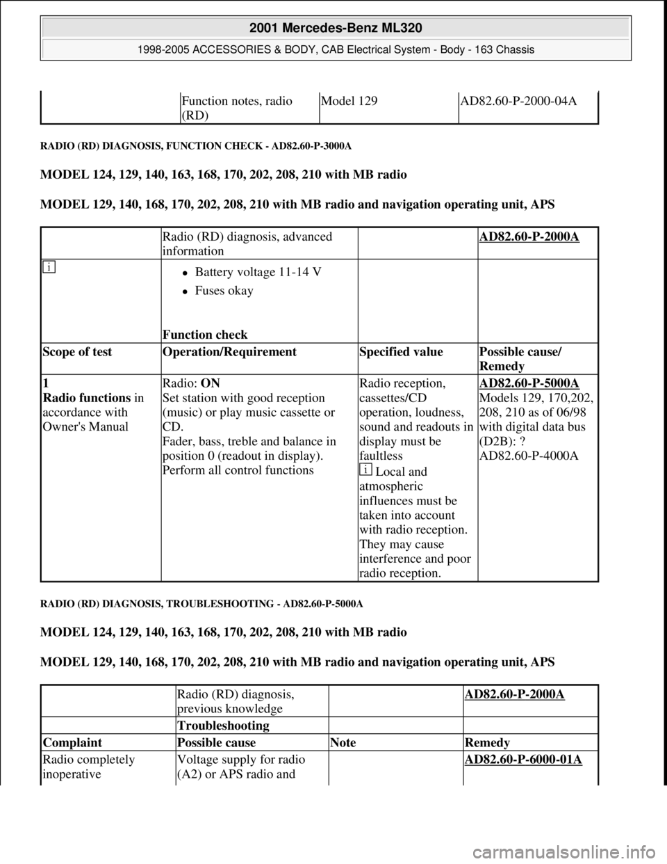
RADIO (RD) DIAGNOSIS, FUNCTION CHECK - AD82.60-P-3000A
MODEL 124, 129, 140, 163, 168, 170, 202, 208, 210 with MB radio
MODEL 129, 140, 168, 170, 202, 208, 210 with MB radio and navigation operating unit, APS
RADIO (RD) DIAGNOSIS, TROUBLESHOOTING - AD82.60-P-5000A
MODEL 124, 129, 140, 163, 168, 170, 202, 208, 210 with MB radio
MODEL 129, 140, 168, 170, 202, 208, 210 with MB radio and navigation operating unit, APS
Function notes, radio
(RD)Model 129AD82.60-P-2000-04A
Radio (RD) diagnosis, advanced
information AD82.60-P-2000A
Battery voltage 11-14 V
Fuses okay
Function check
Scope of test Operation/Requirement Specified value Possible cause/
Remedy
1
Radio functions in
accordance with
Owner's ManualRadio: ON
Set station with good reception
(music) or play music cassette or
CD.
Fader, bass, treble and balance in
position 0 (readout in display).
Perform all control functionsRadio reception,
cassettes/CD
operation, loudness,
sound and readouts in
display must be
faultless
Local and
atmospheric
influences must be
taken into account
with radio reception.
They may cause
interference and poor
radio reception.AD82.60-P-5000A
Models 129, 170,202,
208, 210 as of 06/98
with digital data bus
(D2B): ?
AD82.60-P-4000A
Radio (RD) diagnosis,
previous knowledge AD82.60-P-2000A
Troubleshooting
Complaint Possible cause Note Remedy
Radio completely
inoperativeVoltage supply for radio
(A2) or APS radio and AD82.60-P-6000-01A
2001 Mercedes-Benz ML320
1998-2005 ACCESSORIES & BODY, CAB Electrical System - Body - 163 Chassis
me
Saturday, October 02, 2010 3:30:07 PMPage 205 © 2006 Mitchell Repair Information Company, LLC.