1997 MERCEDES-BENZ ML320 air condition
[x] Cancel search: air conditionPage 3753 of 4133

9
Detach return line (30f) and high-pressure
expansion hose (30i)
Connection fittings or banjo bolts
depending on the version. Seal off line
connections with plugs.
Installation:
Replace sealing rings.
Connection fitting, return line
*BA46.20-P-1001-01D
Connection fitting, high-pressure
expansion hose
*BA46.20-P-1002-01D
Banjo bolt, return line
*BA46.20-P-1004-01D
Banjo bolt, high-pressure expansion hose
*BA46.20-P-1005-01D
Plug
*129589009100
10
Detach nut (25d) and bolt from steering
coupling (25) and pull lower steering shaft
(80a) upwards out of steering coupling (25)
Do not use force as the corrugated tube is
sensitive to lateral forces. Enlarge clamping
groove a little with a screwdriver if necessary.
Installation:
Replace nut (25d).
Installation:
Turn rack-and-pinion
steering to center position and fit steering
coupling.
AR46.20-P-0600-01GH
*BA46.10-P-1001-01D
11
Detach rack-and-pinion steering (23) from
front axle carrier (1) by unscrewing bolts (23a)
The installed position of the shims (23h,
23i) on the right-hand side, between the
rubber mount and the front axle carrier, must
be observed as the shims are of different
thicknesses.
Installation:
Attach rack-and-pinion
steering to front axle carrier.
AR46.20-P-0600-03GH
Assessing condition of steering gear when
repairing accident vehicles
AH46.20-P-9409-01A
12
Check rubber mount (21) of rack-and-pinion
steering mounting for damage
Replace rubber mount if necessary:
#
Removing rubber mounts on rack-and-pinion
steering mounting
AR46.20-P-0600-02GH
13
Install in the reverse order
14
Fill and bleed power steering pump
Engines 112, 113
AR46.30-P-0010B
Engines 111, 612, 628
AR46.30-P-0010P
15
Check steering for function and leaks
There is a grease cushion under the cover
cap. A small amount of escaping grease is to
be regarded as normal and must not be
confused with leakage.
16.1
Check toe on front axle and adjust if necessary
When installing a new rack-and-pinion
steering, see:
#
Performing chassis alignment check
AR40.20-P-0200A
Steering shaft
Number
Designation
Model 163
BA46.10-P-1001-01D
Self-locking nut, steering coupling to steering shaft
and rack-and-pinion steering
Nm
28
Steering gear
Number
Designation
Model 163
BA46.20-P-1001-01D
Screwed connection fitting from return line
to rack-and-pinion steering
Nm
15
BA46.20-P-1002-01D
Screwed connection fitting from high-
pressure expansion hose to rack-and-pinion
steering
Nm
15
BA46.20-P-1003-01D
Bolted connection, rack-and-pinion steering
to front axle carrierNm
50
BA46.20-P-1004-01D
Banjo bolt, return line to rack-and-pinion
steering
Nm
30
BA46.20-P-1005-01D
Banjo bolt, high-pressure expansion hose to
rack-and-pinion steering
Nm
30
Copyright DaimlerChrysler AG 06.07.2006 CD-Ausgabe G/10/04 . This WIS print-out will not be recorde
d by Modification services.
Page 2
Page 3756 of 4133
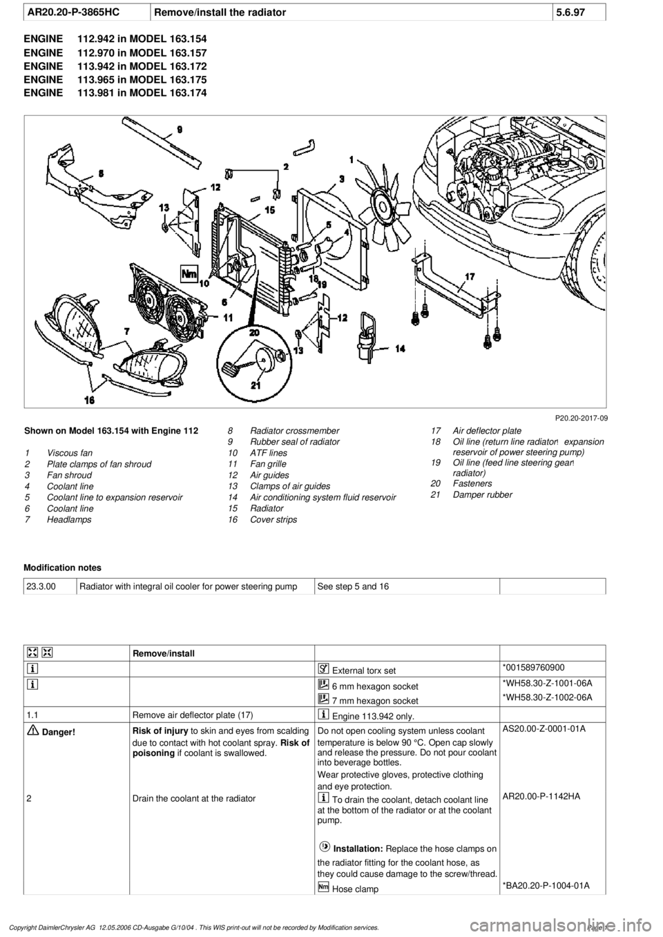
AR20.20-P-3865HC
Remove/install the radiator
5.6.97
ENGINE
112.942 in MODEL 163.154
ENGINE
112.970 in MODEL 163.157
ENGINE
113.942 in MODEL 163.172
ENGINE
113.965 in MODEL 163.175
ENGINE
113.981 in MODEL 163.174
P20.20-2017-09
Shown on Model 163.154 with Engine 112
1
Viscous fan
2
Plate clamps of fan shroud
3
Fan shroud
4
Coolant line
5
Coolant line to expansion reservoir
6
Coolant line
7
Headlamps
17
Air deflector plate
18
Oil line (return line radiator
!
expansion
reservoir of power steering pump)
19
Oil line (feed line steering gear
!
radiator)
20
Fasteners
21
Damper rubber
8
Radiator crossmember
9
Rubber seal of radiator
10
ATF lines
11
Fan grille
12
Air guides
13
Clamps of air guides
14
Air conditioning system fluid reservoir
15
Radiator
16
Cover strips
Modification notes
23.3.00
Radiator with integral oil cooler for power steering pump
See step 5 and 16
Remove/install
External torx set
*001589760900
6 mm hexagon socket
*WH58.30-Z-1001-06A
7 mm hexagon socket
*WH58.30-Z-1002-06A
1.1
Remove air deflector plate (17)
Engine 113.942 only.
Danger!
Risk of injury
to skin and eyes from scalding
due to contact with hot coolant spray.
Risk of
poisoning
if coolant is swallowed.
Do not open cooling system unless coolant
temperature is below 90 °C. Open cap slowly
and release the pressure. Do not pour coolant
into beverage bottles.
Wear protective gloves, protective clothing
and eye protection.
AS20.00-Z-0001-01A
2
Drain the coolant at the radiator
To drain the coolant, detach coolant line
at the bottom of the radiator or at the coolant
pump.
Installation:
Replace the hose clamps on
the radiator fitting for the coolant hose, as
they could cause damage to the screw/thread. AR20.00-P-1142HA
Hose clamp
*BA20.20-P-1004-01A
Copyright DaimlerChrysler AG 12.05.2006 CD-Ausgabe G/10/04 . This WIS print-out will not be recorde
d by Modification services.
Page 1
Page 3757 of 4133

3.1
Remove viscous fan (1)
Engine 112.942 /970 and 113.942.
Right-hand thread!
AR20.40-P-5660C
3.2
Remove electric fan
Only Engine 113.965 /981.
AR20.40-P-5000GH
4.1
Pull off plate clamps of fan shroud (2)
Only for Engine 112.942, from 5/98.
5.1
Remove fan shroud (3)
Only for Engine 112.942 /970 und
113.942. Unscrew the bolts at bottom of fan
shroud for this step
Installation:
If installing a new radiator
with integral power steering pump oil cooler, a
new fan shroud is required if a radiator
without integral oil cooler was previously
installed.
6
Remove headlamp (7).
AR82.10-P-4730GH
7
Remove radiator crossmember (8)
AR62.30-P-2300GH
8
Detach coolant line (4, 6) and expansion
reservoir coolant line (5) at the radiator
Installation:
Replace the hose clamps on
the radiator fitting for the coolant hose, as
they could cause damage to the screw/thread.
Hose clamp
*BA20.20-P-1004-01A
9
Remove the rubber seal on radiator (9)
10.1
Remove oil line (return line of radiator
!
power steering pump expansion reservoir)
(18) and oil line (feed line of steering gear
!
radiator) (19)
From 5/98 only, seal off the connections.
Set of plugs
*129589009100
11
Unscrew ATF lines (10) at the radiator
Seal off the connections.
*BA20.20-P-1001-01A
*BA20.20-P-1003-01A
Set of plugs
*129589009100
12.1
Detach the connector from the fan and
remove the fan grille (11)
Only for Engine 112.942 /970 and 113.942.
13
Unscrew the condenser from the radiator
Do not disconnect the lines.
14
Remove fasteners (20) and damper rubber
(21)
The damper rubber (21) is designed to
prevent possible vibrations between the
condenser and radiator (15) during off-road
driving.
15
Remove air conditioning system fluid
reservoir (14) from the radiator
Place aside with the lines connected.
Detach the condenser from the radiator.
16
Remove radiator (15)
When installing, the spigots on the
radiator must be inserted in the rubber
grommets in the bottom crossmember.
Installation:
On Model 163.154 with
Engine 112.942 before VIN end number
043553, when installing a new radiator with
integral power steering pump oil cooler,
additional operations are required, if they
have not already been carried out:
#
v
Retrofit the bracket for the oil cooler line of
the power steering pump
SM46.30-P-0002A
k
Radiator with integral oil cooler for the power
steering pump
BT20.20-P-0001-01A
17
Detach air guides (12)
Replace the clamps on air guides (13).
18
Install in the reverse order
19
Pour in coolant
AR20.00-P-1142HA
20
Check the headlamp setting and correct if
necessary
e
Check and adjust the headlamp setting
AP82.10-P-8260GH
Danger!
Risk of accident
caused by vehicle starting
off when engine is running.
Risk of injury
caused by contusions and burns when
working in engine during starting procedure
Secure the vehicle to prevent it from moving.
Wear closed and snug-fitting work clothes.
Do not grasp hot or rotating parts.
AS00.00-Z-0005-01A
21
Check the oil level in the automatic
transmission and correct if necessary
AR27.00-P-0101A
22
Check the cooling system for leaks
AR20.00-P-1010HA
Radiator, coolant hoses
Copyright DaimlerChrysler AG 12.05.2006 CD-Ausgabe G/10/04 . This WIS print-out will not be recorde
d by Modification services.
Page 2
Page 3760 of 4133
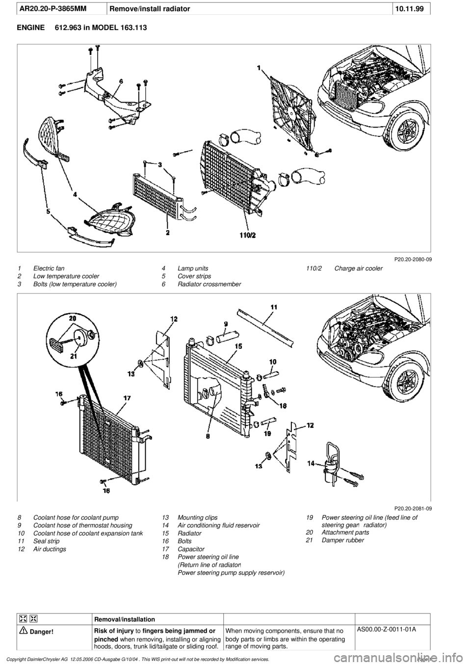
AR20.20-P-3865MM
Remove/install radiator
10.11.99
ENGINE
612.963 in MODEL 163.113
P20.20-2080-09
1
Electric fan
2
Low temperature cooler
3
Bolts (low temperature cooler)
110/2
Charge air cooler
4
Lamp units
5
Cover strips
6
Radiator crossmember
P20.20-2081-09
8
Coolant hose for coolant pump
9
Coolant hose of thermostat housing
10
Coolant hose of coolant expansion tank
11
Seal strip
12
Air ductings
19
Power steering oil line (feed line of
steering gear
!
radiator)
20
Attachment parts
21
Damper rubber
13
Mounting clips
14
Air conditioning fluid reservoir
15
Radiator
16
Bolts
17
Capacitor
18
Power steering oil line
(Return line of radiator
!
Power steering pump supply reservoir)
Removal/installation
Danger!
Risk of injury
to
fingers being jammed or
pinched
when removing, installing or aligning
hoods, doors, trunk lid/tailgate or sliding roof.
When moving components, ensure that no
body parts or limbs are within the operating
range of moving parts.
AS00.00-Z-0011-01A
Copyright DaimlerChrysler AG 12.05.2006 CD-Ausgabe G/10/04 . This WIS print-out will not be recorde
d by Modification services.
Page 1
Page 3761 of 4133

Danger!
Risk of injury
to skin and eyes suffering
scalding from contact with hot coolant spray.
Risk of poisoning
from swallowing coolant.
Do not open cooling system unless coolant
temperature is below 90 °C. Open cap slowly
and release the pressure. Do not pour coolant
into beverage bottles.
Wear protective gloves, protective clothing
and eye protection.
AS20.00-Z-0001-01A
1
Open engine hood and raise to vertical position
Have second person secure hood.
AR88.40-P-1000GI
2
Connect no load current retention unit
*WH58.30-Z-1005-09A
3
Disconnect battery ground cable
AR54.10-P-0003A
4
Remove trim panel of cylinder head cover
AR01.20-P-5014-02B
*BA01.20-P-1002-01A
*BA01.20-P-1003-01A
5
Remove bottom part of noise encapsulation
at front
AR94.30-P-5400GH
6
Remove electric fan (1)
Remove toward bottom.
AR20.40-P-5000M
7
Drain coolant
At radiator.
AR20.00-P-1142M
Notes on coolant
All engines
AH20.00-N-2080-01A
8
Remove charge air cooler (110/2)
AR09.41-P-6817MM
9.1
Attach guard plate for radiator/condenser
With automatic air conditioning, code
581a and AC system or Tempmatic USA,
code 580.
Attach additional AC condenser in the
vehicle.
y
Guard plate for radiator/condenser
Engine 606 in model 124,
Engine 606.961 in model 140,
Engine 112, 113, 604, 605, 611.960 in
MODEL 202,
Engine 602.983, 612.966 in MODEL 461,
Engine 628.962, 612.965, 606.964, 112.945,
113.962/ 982 in MODEL 463,
Engine 111, 112, 611.962, 612.962 in model
203,
Engines 112, 113, 611.961, 612.961, 613.961
in MODEL 210,
Engine 112 in model 170,
Engine 112 in MODEL 220,
Engine 113 in MODEL 211, 215, 220,
Engine 112 in MODEL 208,
Engine 112, 612.963, 628.963 in MODEL 163,
Engine 112.923 /943, 113.961 in MODEL 129,
Engine 137, 275 in MODEL 215, 220,
Engine 613.960, 628.960 in MODEL 220,
Engine 113.992 in model 230.474,
Engine 271 in model 209, 203,
Engine 285.950 in model 240.078 /178,
Engine 612.967 in model 209.316,
Engine 648 in model 220
Engine 112.951 in model 639.601/603/
605/701/703/705/801/803/805
Engine 646.983/984 in model 639.601/
603/605/701/703/705/801/803/805
Engine 646.982 in model
639.601/603/605/701/703/705
WF58.50-P-0110-01A
10
Remove seal rail (11)
11
Extract steering oil from reservoir
Hand pump
*210589007100
12.1
Disconnect power steering oil line (return line
radiator
!
power steering pump supply
reservoir) (18)
Seal connections.
Installation:
Install new sealing rings.
*BA46.30-P-1012-01A
Clamp
*000589543700
Set of stop plugs
*129589009100
12.2
Disconnect power steering oil line (feed line of
steering gear
!
radiator) (19)
Clamp
*000589543700
Set of stop plugs
*129589009100
Hexagon socket wrench
*WH58.30-Z-1001-06A
Hexagon socket wrench
*WH58.30-Z-1002-06A
Copyright DaimlerChrysler AG 12.05.2006 CD-Ausgabe G/10/04 . This WIS print-out will not be recorde
d by Modification services.
Page 2
Page 3778 of 4133
8.1
Check wheel sensor, valve body and sealing
rubber for damage
Vehicles with tire pressure monitor (code 475)
Do not remove wheel sensor for this.
Do not use compressed air, solvents or
detergents to clean the wheel sensor. Wipe
off dirt with a clean, lint-free cloth only.
Do not retighten the female torx bolt and
union nut.
Replace all valve components of wheel
electronics if:
D
The wheel sensor mounting bolt or union
nut is visibly loose.
Replace the wheel sensor if:
D
The wheel sensor is obviously damaged.
D
Tire sealant was used.
Install new wheel sensors:
#
Replace wheel sensor.
AR40.15-P-0080A
8.2
Install new valve (43g).
Vehicles without tire pressure monitor (code
475)
9
Checking condition of rim
AR40.10-P-1010-01A
Mounting
10
Moisten rim flange and tire beads with soapy
water and align assembly head at a small
distance (X, Y) to the disk wheel
Only use soapy water for fitting and
removing tires.
11
Place tire obliquely on the rim and pull on
over the rim flange using the tire installer
Position wheels with wheel sensors so
that the wheel sensor is approximately 180°
opposite the mounting head.
Do not apply compressive force to the wheel
sensor otherwise it will be damaged.
Observe the running direction on tires with
specified running direction.
Put as little stress as possible on bead
area.
12
Align the match points of the tire and disk
wheel with each other and remove the disk
wheel with tire from the tire mounting device
13
Inflate tires without valve element up to max.
3 bar
Do
not
unscrew valve element on disk
wheels with tire pressure monitor sensor.
The tire must slide evenly over the safety
shoulders of the disk wheel, otherwise coat
the tire beads with soapy water again.
14
Screw the valve element into the valve (43g)
and adjust the tire inflation pressure to the
specified value
Observe the tire pressure information in
the fuel filler flap of the vehicle.
15
Balance wheel
AR40.10-P-1040A
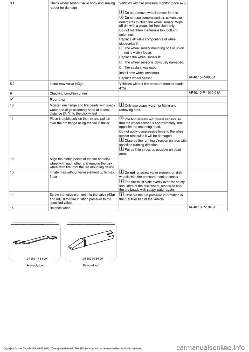
124 589 17 63 00 129 589 00 59 00
Removal tool
Assembly tool
Copyright DaimlerChrysler AG 06.07.2006 CD-Ausgabe G/10/04 . This WIS print-out will not be recorde
d by Modification services.
Page 2
Page 3857 of 4133
different engine loads, e.g. power steering turned to full lock, engaging drive mode, switching on AC
compressor
different mixture, e.g. from activated charcoal canister if purging activated (depending on activated
charcoal charge)
Function
The actuator EFP/TPM/LLR (additional designation: throttle valve actuator) regulates the idling speed by
changing the throttle valve position. It is actuated by the ME-SFI control unit.
The ME-SFI control unit actuates the throttle valve motor (M16/1 m1) in line with the input signals received at
the ME-SFI control unit (N3/10).
Heating speed of the catalytic converter
In order to warm up the catalytic converter more rapidly to operating temperature, engine speed is increased in
the idle speed range to 1100 up to 1500 rpm for about 20 seconds after each starting procedure at coolant
temperatures of < 40 °C. When a Drive position is engaged, engine speed is immediately controlled to a lower
value.
Automatic transmission
When a drive position is engaged, a lower engine speed is controlled in order to reduce the creeping tendency o
f
the vehicle. The information "Drive position engaged/not engaged" is transmitted by the ETC control unit
(N15/3) over the CAN databus to the ME-SFI control unit.
Ignition angle
To assist the idle speed control, the ignition angle can be retarded by as much as 36° crank angle or advanced by
as much as 20° crank angle from the calculated specified value.
The control in the idle speed range by altering the ignition angle reacts more rapidly than altering the position o
f
the throttle valve.
The idling speed can be influenced with HHT or the STAR DIAGNOSIS.
AC compressor
In order to avoid engine speed dropping in the idle speed range when the AC compressor is engaged, the AC
push-button control unit (N19) or automatic air conditioning push-button control unit (N22) supplies a signal to
the ME-SFI control unit (as of approx. 6/96 over CAN) and the opening cross-section of the throttle valve is
enlarged.
When the air conditionin
g unit is switched on and the external temperature exceeds 35° C the idling speed on
2001 Mercedes-Benz ML320
1998-2005 ACCESSORIES & BODY CAB Throttle Control, Speed Control Systems - 163 Chassis
me
Saturday, October 02, 2010 3:36:27 PMPage 17 © 2006 Mitchell Repair Information Company, LLC.
Page 3861 of 4133
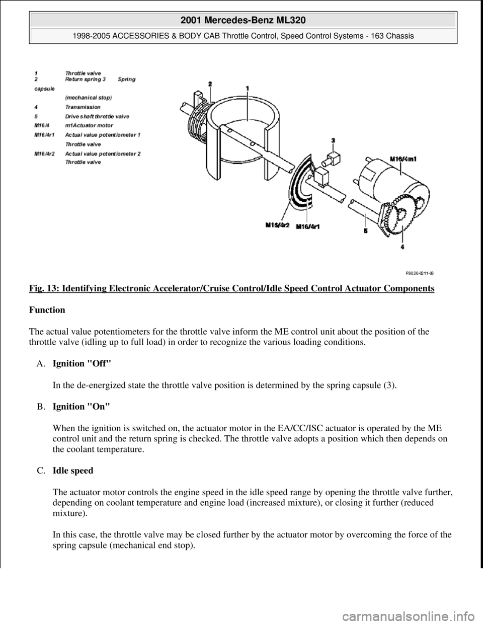
Fig. 13: Identifying Electronic Accelerator/Cruise Control/Idle Speed Control Actuator Components
Function
The actual value potentiometers for the throttle valve inform the ME control unit about the position of the
throttle valve (idling up to full load) in order to recognize the various loading conditions.
A.Ignition "Off"
In the de-energized state the throttle valve position is determined by the spring capsule (3).
B.Ignition "On"
When the ignition is switched on, the actuator motor in the EA/CC/ISC actuator is operated by the ME
control unit and the return spring is checked. The throttle valve adopts a position which then depends on
the coolant temperature.
C.Idle speed
The actuator motor controls the engine speed in the idle speed range by opening the throttle valve further,
depending on coolant temperature and engine load (increased mixture), or closing it further (reduced
mixture).
In this case, the throttle valve may be closed further by the actuator motor by overcoming the force of the
sprin
g capsule (mechanical end stop).
2001 Mercedes-Benz ML320
1998-2005 ACCESSORIES & BODY CAB Throttle Control, Speed Control Systems - 163 Chassis
me
Saturday, October 02, 2010 3:36:27 PMPage 21 © 2006 Mitchell Repair Information Company, LLC.