1997 MERCEDES-BENZ ML320 water pump
[x] Cancel search: water pumpPage 3296 of 4133
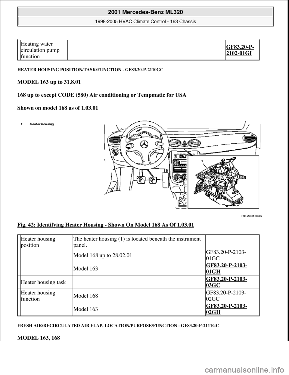
HEATER HOUSING POSITION/TASK/FUNCTION - GF83.20-P-2110GC
MODEL 163 up to 31.8.01
168 up to except CODE (580) Air conditioning or Tempmatic for USA
Shown on model 168 as of 1.03.01
Fig. 42: Identifying Heater Housing
- Shown On Model 168 As Of 1.03.01
FRESH AIR/RECIRCULATED AIR FLAP, LOCATION/PURPOSE/FUNCTION - GF83.20-P-2111GC
MODEL 163, 168
Heating water
circulation pump
function
GF83.20-P-
2102-01GI
Heater housing
positionThe heater housing (1) is located beneath the instrument
panel.
Model 168 up to 28.02.01GF83.20-P-2103-
01GC
Model 163GF83.20-P-2103-
01GH
Heater housing task GF83.20-P-2103-
03GC
Heater housing
functionModel 168GF83.20-P-2103-
02GC
Model 163GF83.20-P-2103-
02GH
2001 Mercedes-Benz ML320
1998-2005 HVAC Climate Control - 163 Chassis
me
Saturday, October 02, 2010 3:23:15 PMPage 52 © 2006 Mitchell Repair Information Company, LLC.
Page 3325 of 4133
The residual engine heat utilization system allows the vehicle to be heated even when the ignition is
switched OFF. To do so the system utilizes the residual heat from the engine and guides it via the
blower into the passenger compartment. The heating water circulation pump ensures that the
coolant is properly circulated.
Automatic air conditioning push-button control module
The automatic air conditioning can be operated by the driver using various tip switches. Apart from this
the push-
button control module reads in different sensor signals, processes them and controls components
in the automatic air conditioning.
Rear ventilation control panel
The operator can intervene in the automatic regulation of the rear ventilation through the automatic air
conditioning by using the rear ventilation control panel and adjust it accordingly to suit needs at any
given time. With the aid of the air distribution switch and blower switch the operator can accommodate
his/her own wishes. The correspondingly altered function is then no longer regulated by the automatic air
conditioning.
By pressing the automatic control button the manually initiated settings can be reset and thus regulated
again by the automatic air conditioning.
Regulation of the air quantity and air distribution ensues thus solely by way of the automatic air
conditioning push-button control module.
Heater circuit
Coolant is heated by the engine. Subsequently, the heated coolant is then routed through the heat exchanger,
where the heat is dissipated to the air in the passenger compartment. The heater return line, in which the heating
water circulation pump is located, takes the coolant back to the coolant pump.
The heating water circulation pump ensures that the coolant is properly circulated.
The coolant flows through the heat exchanger permanently.
Depending upon the desired in-car temperature, regulation is conducted over the blending air flaps, which are
operated by the blending air flap actuator motor.
Heater operation with heater booster in vehicles with OM 612.963
In vehicles equipped with direct-injection diesel engines, an electrical heater booster is additionally installed in
the evaporator housing downstream of the heat exchanger, in order to compensate the heater output deficit
which occurs in the case of certain operating conditions.
The 3 heating elements in the heater booster are supplied with current, as a result of which they are heated and
start to glow. As a result of the structural conditions, it is ensured that the drawn in fresh air flows directly past
the electric heater booster, and is therefore heated.
2001 Mercedes-Benz ML320
1998-2005 HVAC Climate Control - 163 Chassis
me
Saturday, October 02, 2010 3:23:16 PMPage 81 © 2006 Mitchell Repair Information Company, LLC.
Page 3328 of 4133
The control module integrated in the AAC push-button control module (N22) looks after all system regulation
and control functions such as:
comparing preselected and actual temperatures and controlling the air temperature at the air outlets
automatic switchover from fresh air to recirculated air mode
electrical control of refrigerant compressor
controlling the auxiliary fan or the electric suction-type fan motor/ air conditioning with integrated
control
The AAC push-button control module (N22) has a diagnostic capability. Consequently, any faults which occur
are stored in the fault memory which can be read with the help of the diagnosis assistant system (DAS).
When the AAC push-button control module is replaced (N22), variant coding must be carried out using the
Diagnosis Assistant System (DAS).
The AAC push-button control module (N22) also performs the following actuations:
direct: refrigerant compressor; heating water circulation pump; PTC heater booster (OM 612 only), rear
window heater
via the CAN BUS: auxiliary fan, electric suction-type fan motor/air conditioning with integrated control,
blower control and air distribution in the rear compartment (automatic mode)
via the AC bus: blower motor; 8 stepping motors for air distribution
The following sensor signals are read in by the AAC push-button control module (N22):
direct: temperature sensor evaporator, pressure and temperature sensor refrigerant, in-car temperature
sensor, center nozzle vent air temperature sensor, footwell and rear passenger compartment, sun sensor
via the CAN BUS: Ambient temperature display temperature sensor, sensor for specified values in rear
control panel
REFRIGERANT CIRCUIT FUNCTION - GF83.40-P-2001GH
MODEL 163 up to 31.8.01 with CODE (580) Air conditioning or Tempmatic for USA
Blower switch, location/task/design/function GF83.25-P-2100GI
Temperature selector wheel, location/task/ design/function GF83.25-P-2102GI
Air distribution switch, location/task/design/ function GF83.25-P-2101GI
Defroster button, location/task/function GF83.40-P-2139GI
Recirculating air push-button, location/task/ function GF83.40-P-2145GI
Auto button, location/task/function GF83.40-P-2147GI
AC OFF button, location/task/function GF83.40-P-2107GI
Rest push-button, location/task/function GF83.40-P-2148GI
Rear passenger compartment air distribution button, location/task/function GF83.40-P-2173GI
2001 Mercedes-Benz ML320
1998-2005 HVAC Climate Control - 163 Chassis
me
Saturday, October 02, 2010 3:23:16 PMPage 84 © 2006 Mitchell Repair Information Company, LLC.
Page 3362 of 4133
function 2146GI
Blower motor,
location/purpose/design/function GF83.10-P-
2170GI
Blower regulator, location/purpose/function GF83.10-P-
2141GI
Rear blower motor, location/purpose/design/
function GF83.10-P-
2168GI
Rear electronic blower regulator, location/
purpose/function GF83.10-P-
2176GI
Combination filter, location/purpose/function GF83.10-P-
2128GI
Defroster vent flap actuator motor, location/
purpose/function GF83.10-P-
2175GI
Footwell flap actuator,
location/purpose/function GF83.10-P-
2132GI
Actuator motor, center nozzle flap, location/
purpose/function GF83.10-P-
2172GI
Actuator motor, rear shut-off flap, location/
purpose/function GF83.10-P-
2171GI
Actuator motor, rear air distribution flap,
location/purpose/function GF83.10-P-
2173GI
Heating system heat exchanger, location/
purpose/function GF83.20-P-
2108GC
Heating water circulation pump, location/
purpose/function GF83.20-P-
2109GI
Fresh air/recirculation flap, location/purpose/
function GF83.20-P-
2111GC
Fresh air/recirculation flap actuator, location/
purpose/function GF83.30-P-
2116GC
Blower switch,
location/purpose/design/function GF83.25-P-
2100GI
Blower button, location/purpose/functionRear ventilation operating moduleGF83.40-P-
2144GI
Air distribution switch,
location/purpose/design/ function GF83.25-P-
2101GI
Air distribution button,
location/purpose/functionRear ventilation operating moduleGF83.40-P-
2159GI
Temperature selector wheel, location/purpose/
design/function GF83.25-P-
2102GI
Defroster button, location/purpose/function GF83.40-P-
2139GI
Recirculating air push-button,
location/purpose/ function GF83.40-P-
2145GI
GF83.40-P-
2001 Mercedes-Benz ML320
1998-2005 HVAC Climate Control - 163 Chassis
me
Saturday, October 02, 2010 3:23:16 PMPage 118 © 2006 Mitchell Repair Information Company, LLC.
Page 3397 of 4133
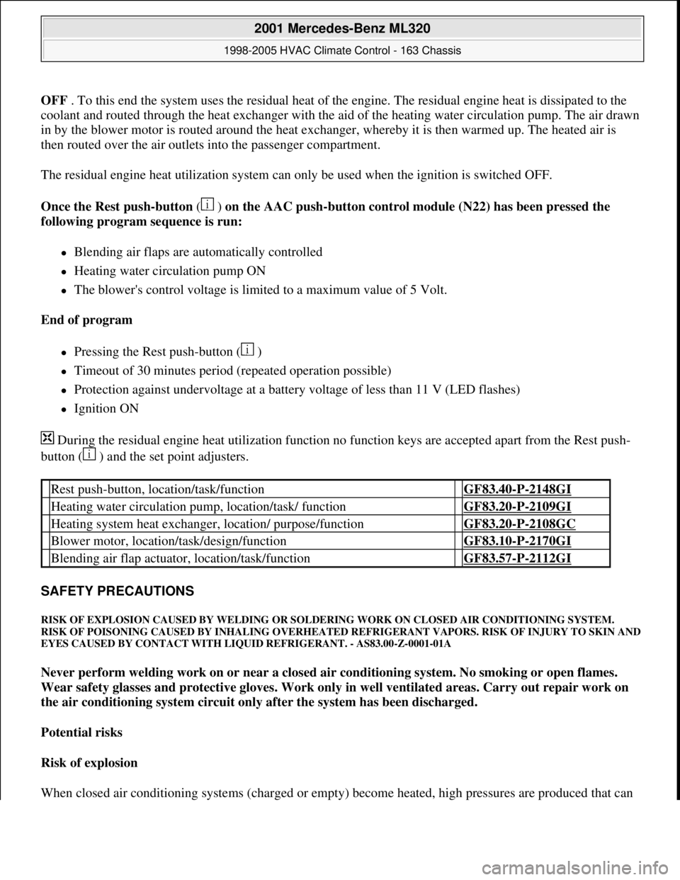
OFF . To this end the system uses the residual heat of the engine. The residual engine heat is dissipated to the
coolant and routed through the heat exchanger with the aid of the heating water circulation pump. The air drawn
in by the blower motor is routed around the heat exchanger, whereby it is then warmed up. The heated air is
then routed over the air outlets into the passenger compartment.
The residual engine heat utilization system can only be used when the ignition is switched OFF.
Once the Rest push-button ( ) on the AAC push-button control module (N22) has been pressed the
following program sequence is run:
Blending air flaps are automatically controlled
Heating water circulation pump ON
The blower's control voltage is limited to a maximum value of 5 Volt.
End of program
Pressing the Rest push-button ( )
Timeout of 30 minutes period (repeated operation possible)
Protection against undervoltage at a battery voltage of less than 11 V (LED flashes)
Ignition ON
During the residual engine heat utilization function no function keys are accepted apart from the Rest push-
button ( ) and the set point adjusters.
SAFETY PRECAUTIONS
RISK OF EXPLOSION CAUSED BY WELDING OR SOLDERING WORK ON CLOSED AIR CONDITIONING SYSTEM.
RISK OF POISONING CAUSED BY INHALING OVERHEATED REFRIGERANT VAPORS. RISK OF INJURY TO SKIN AND
EYES CAUSED BY CONTACT WITH LIQUID REFRIGERANT. - AS83.00-Z-0001-01A
Never perform welding work on or near a closed air conditioning system. No smoking or open flames.
Wear safety glasses and protective gloves. Work only in well ventilated areas. Carry out repair work on
the air conditioning system circuit only after the system has been discharged.
Potential risks
Risk of explosion
When closed air conditionin
g systems (charged or empty) become heated, high pressures are produced that can
Rest push-button, location/task/function GF83.40-P-2148GI
Heating water circulation pump, location/task/ function GF83.20-P-2109GI
Heating system heat exchanger, location/ purpose/function GF83.20-P-2108GC
Blower motor, location/task/design/function GF83.10-P-2170GI
Blending air flap actuator, location/task/function GF83.57-P-2112GI
2001 Mercedes-Benz ML320
1998-2005 HVAC Climate Control - 163 Chassis
me
Saturday, October 02, 2010 3:23:17 PMPage 153 © 2006 Mitchell Repair Information Company, LLC.
Page 3406 of 4133
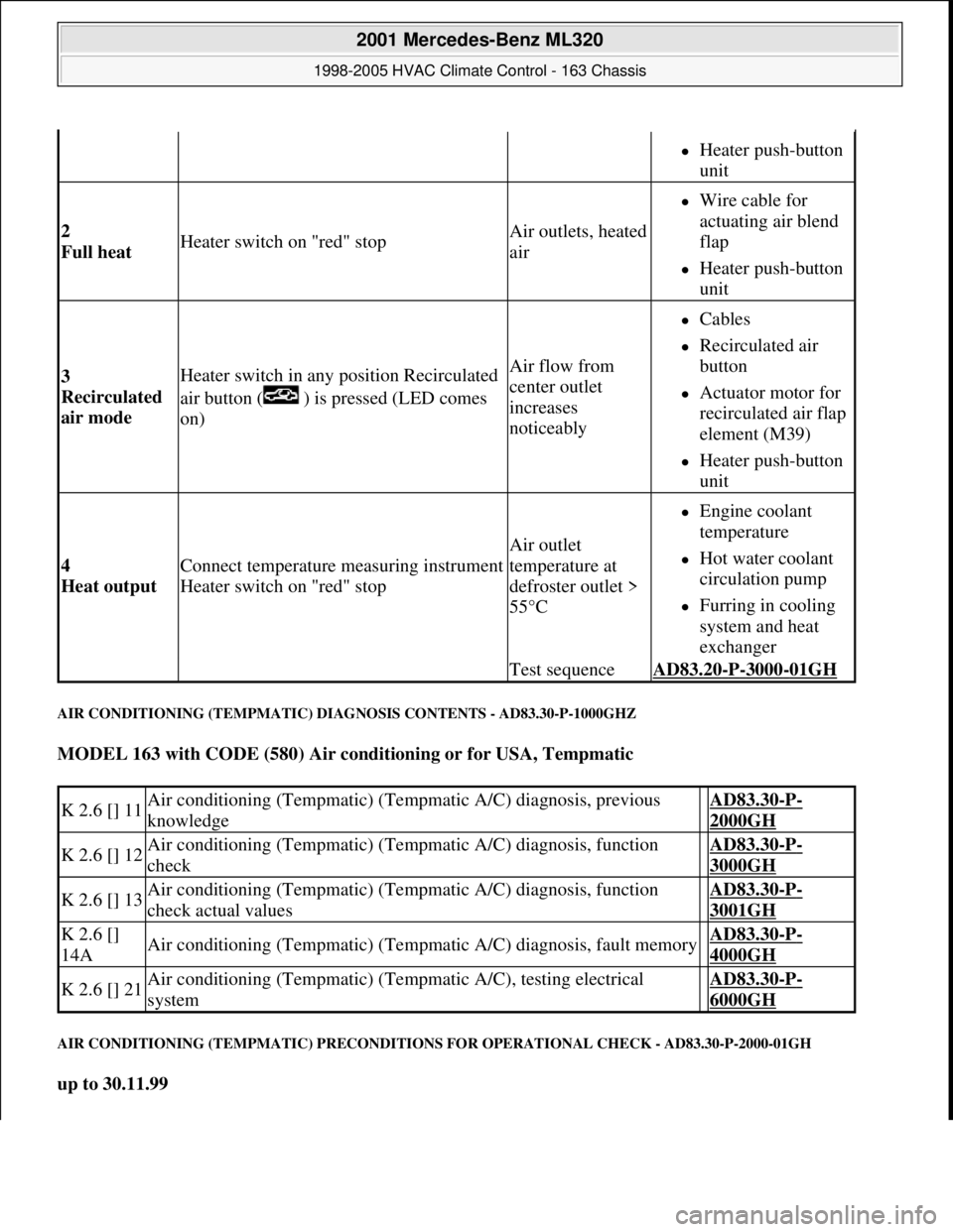
AIR CONDITIONING (TEMPMATIC) DIAGNOSIS CONTENTS - AD83.30-P-1000GHZ
MODEL 163 with CODE (580) Air conditioning or for USA, Tempmatic
AIR CONDITIONING (TEMPMATIC) PRECONDITIONS FOR OPERATIONAL CHECK - AD83.30-P-2000-01GH
up to 30.11.99
Heater push-button
unit
2
Full heat Heater switch on "red" stopAir outlets, heated
air
Wire cable for
actuating air blend
flap
Heater push-button
unit
3
Recirculated
air mode Heater switch in any position Recirculated
air button ( ) is pressed (LED comes
on)Air flow from
center outlet
increases
noticeably
Cables
Recirculated air
button
Actuator motor for
recirculated air flap
element (M39)
Heater push-button
unit
4
Heat output Connect temperature measuring instrument
Heater switch on "red" stop
Air outlet
temperature at
defroster outlet >
55°C
Engine coolant
temperature
Hot water coolant
circulation pump
Furring in cooling
system and heat
exchanger
Test sequenceAD83.20-P-3000-01GH
K 2.6 [] 11Air conditioning (Tempmatic) (Tempmatic A/C) diagnosis, previous
knowledge AD83.30-P-
2000GH
K 2.6 [] 12Air conditioning (Tempmatic) (Tempmatic A/C) diagnosis, function
check AD83.30-P-
3000GH
K 2.6 [] 13Air conditioning (Tempmatic) (Tempmatic A/C) diagnosis, function
check actual values AD83.30-P-
3001GH
K 2.6 []
14AAir conditioning (Tempmatic) (Tempmatic A/C) diagnosis, fault memory AD83.30-P-
4000GH
K 2.6 [] 21Air conditioning (Tempmatic) (Tempmatic A/C), testing electrical
system AD83.30-P-
6000GH
2001 Mercedes-Benz ML320
1998-2005 HVAC Climate Control - 163 Chassis
me
Saturday, October 02, 2010 3:23:17 PMPage 162 © 2006 Mitchell Repair Information Company, LLC.
Page 3414 of 4133
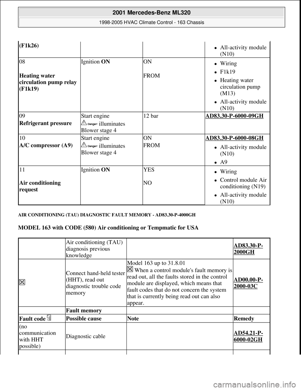
AIR CONDITIONING (TAU) DIAGNOSTIC FAULT MEMORY - AD83.30-P-4000GH
MODEL 163 with CODE (580) Air conditioning or Tempmatic for USA
(F1k26) All-activity module
(N10)
08Ignition ON ONWiring
F1k19
Heating water
circulation pump
(M13)
All-activity module
(N10)
Heating water
circulation pump relay
(F1k19) FROM
09Start engine12 barAD83.30-P-6000-09GH
Refrigerant pressure illuminates
Blower stage 4
10Start engineONAD83.30-P-6000-08GH
A/C compressor (A9) illuminates
Blower stage 4FROMAll-activity module
(N10)
A9
11Ignition ON YESWiring
Control module Air
conditioning (N19)
All-activity module
(N10)
Air conditioning
request NO
Air conditioning (TAU)
diagnosis previous
knowledge
AD83.30-P-
2000GH
Connect hand-held tester
(HHT), read out
diagnostic trouble code
memory
Model 163 up to 31.8.01
When a control module's fault memory is
read out, all the faults stored in the control
module are displayed, which means that
fault codes that do not concern the system
that is currently being read out can also
appear.
AD00.00-P-
2000-03C
Fault memory
Fault code Possible cause Note Remedy
(no
communication
with HHT
possible)
Diagnostic cable AD54.21-P-
6000-02GH
2001 Mercedes-Benz ML320
1998-2005 HVAC Climate Control - 163 Chassis
me
Saturday, October 02, 2010 3:23:17 PMPage 170 © 2006 Mitchell Repair Information Company, LLC.
Page 3772 of 4133

2
Drain the coolant
Engine 611.960/961/962,
612.961/962/967/990, 613.960/961,
628.960/961/963, 646, 647, 648
AR20.00-P-1142HB
Engine 612.963
AR20.00-P-1142M
3
Remove coolant thermostat (20)
Engine 611, 612, 613, 646, 647, 648
AR20.10-P-2460PP
Engine 628.960/963
AR20.10-P-2460M
4
Mount the housing to remove oil and flush the
cooling/heating system
The housing may be used only for the
purpose of removing the oil, and must be
removed again after it has been rinsed.
Engine 611.960/961/962/ 612.961/962
/963/967/990, 613.960/961
*BA20.10-P-1005-01A
Engine 628.960/961/962/963
*BA20.10-P-1002-01F
Engine 646.962/963
*BA20.10-P-1002-01G
y
Housing for removing oil and flushing the
cooling/heating system
WF58.50-P-2000-01A
Cleaning
5
Set the heater control to full power
6
Set the auxiliary heater to full power
7
Fill the cooling/heating system with a rinsing
solution
Rinsing solution consisting of 5% cleaning
agent and 95% water.
*BF20.00-P-1001-02E
Cleaning agent
*BR00.45-Z-1001-04A
8
Warm up the engine to operating temperature
at moderate engine speed
While engine is running, hold operating
temperature at 80 °C for about 5 min.
9
Switch off engine and allow the cooling
system to
cool to about 50 °C
10
Drain the rinsing solution completely at the
drain plug of radiator (18)
Observe the environmental instructions of
the manufacturer of the cleaning agent.
11
Fill cooling system with fresh water
Pour fresh water into the coolant
expansion reservoir (1).
12
Warm up the engine to operating temperature
at moderate engine speed
While engine is running, hold the
operating temperature at 80 °C for about
5 min.
13
Drain the fresh water completely at the drain
plug of radiator (18)
Repeat the flushing process until all of the
rinsing solution has been removed.
14
Install in the reverse order
Coolant pump, coolant thermostat
Number
Designation
Engine
611.960/
961
Engine
611.962
Engine
612.961/
963
Engine
612.962/
967/990
BA20.10-P-1005-01A
Bolt of coolant thermostat housing to cylinder head
Nm
9999
Designation
Engine
613.960/
961
BA20.10-P-1005-01A
Bolt of coolant thermostat housing to cylinder head
Nm
9
Designation
Engine
628.960/961/962/
963
Copyright DaimlerChrysler AG 12.05.2006 CD-Ausgabe G/10/04 . This WIS print-out will not be recorde
d by Modification services.
Page 2