Page 1237 of 4133
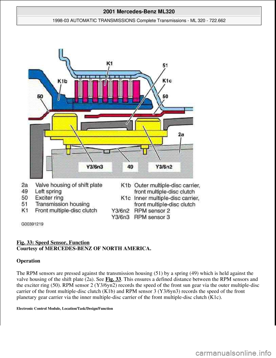
Fig. 33: Speed Sensor, Function
Courtesy of MERCEDES-BENZ OF NORTH AMERICA.
Operation
The RPM sensors are pressed against the transmission housing (51) by a spring (49) which is held against the
valve housing of the shift plate (2a). See Fig. 33
. This ensures a defined distance between the RPM sensors and
the exciter ring (50). RPM sensor 2 (Y3/6yn2) records the speed of the front sun gear via the outer multiple-disc
carrier of the front multiple-disc clutch (K1b) and RPM sensor 3 (Y3/6yn3) records the speed of the front
planetary gear carrier via the inner multiple-disc carrier of the front multiple-disc clutch (K1c).
Electronic Control Module, Location/Task/Design/Function
2001 Mercedes-Benz ML320
1998-03 AUTOMATIC TRANSMISSIONS Complete Transmissions - ML 320 - 722.662
me
Saturday, October 02, 2010 3:15:26 PMPage 68 © 2006 Mitchell Repair Information Company, LLC.
Page 1254 of 4133
Operation
If the piston (B1a) on multiple-disc brake B1 is subjected to oil pressure, it presses the internal and external
discs of the disc set together. See Fig. 44
. The front sun gear (v1) on the housing is locked via the internal
multiple-disc carrier (B1c). the front planetary gears (V2) roll on the front sun gear (V1).
If the rear multiple-disc brake (B2) is engaged via the piston (B2a), then this presses the disc set together. The
center sun gear (M1) is locked against the housing via the internal multiple-disc carrier (B2c). The center
planetary gears (m2) roll on the center sun gear (M1).
If the center multiple disc brake (B3) is engaged via the piston (B3a), then the rear planetary gear carrier (H3)
and the center hollow gear (M4) are locked. When the center multiple-disc brake (B3) is engaged the direction
of rotation reverses.
Multi-Plate Clutch, Location/Task/Design/Function
2001 Mercedes-Benz ML320
1998-03 AUTOMATIC TRANSMISSIONS Complete Transmissions - ML 320 - 722.662
me
Saturday, October 02, 2010 3:15:26 PMPage 85 © 2006 Mitchell Repair Information Company, LLC.
Page 1255 of 4133
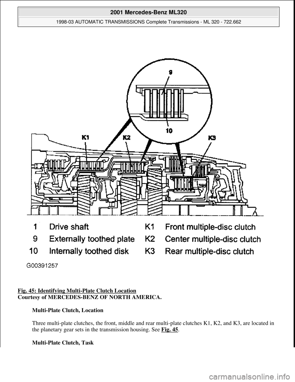
Fig. 45: Identifying Multi-Plate Clutch Location
Courtesy of MERCEDES-BENZ OF NORTH AMERICA.
Multi-Plate Clutch, Location
Three multi-plate clutches, the front , middle and rear multi-plate clutches K1, K2, and K3, are located in
the planetary gear sets in the transmission housing. See Fig. 45
.
Multi-Plate Clutch, Task
2001 Mercedes-Benz ML320
1998-03 AUTOMATIC TRANSMI SSIONS Complete Transmissions - ML 320 - 722.662
me
Saturday, October 02, 2010 3:15:26 PMPage 86 © 2006 Mitchell Repair Information Company, LLC.
Page 1256 of 4133
Produces a non-positive locking connection between two elements of a planetary gear set or between one
element from each of two planetary gear sets in order to transmit the drive torque.
Multi-Plate Clutch, Design
A multi-plate clutch consists of a number of internally toothed discs (10) on an internally toothed disc
carrier and externally toothed discs (9) on an externally toothed disc carrier.
Multi-Plate Clutch, Function
See MULTI
-PLATE CLUTCH, FUNCTION.
Multi-Plate Clutch, Function
2001 Mercedes-Benz ML320
1998-03 AUTOMATIC TRANSMISSIONS Complete Transmissions - ML 320 - 722.662
me
Saturday, October 02, 2010 3:15:26 PMPage 87 © 2006 Mitchell Repair Information Company, LLC.
Page 1258 of 4133
Fig. 46: Multi-Disc Clutch, Function
Courtesy of MERCEDES-BENZ OF NORTH AMERICA.
Operation
Front Multiple-Disc Clutch (K1) - If the piston (K1a) on the front multiple-disc clutch (k1) is subjected to oil
pressure, it presses the internal and external discs of the disc set together. See Fig. 46.
The front sun gear (V1) is connected to the front planetary gear carrier (V3) via the external multiple-disc
carrier (K1b) and the internal multiple-disc carrier (k1b) and the internal multiple-disc carrier (K1c). The front
planetary gear set is thus locked and turns as a closed unit.
Center Multiple-Disc Clutch (K2) - If the center multiple-disc clutch (K2) is engaged via the piston (K2a), the
piston compresses the disc set Via the internal multiple-disc carrier (K2b) and the center planetary gear carrier
(M3) on which the internal discs are seated, the front hollow gear (v4) of the front planetary gear set is
connected to the center hollow gear (M4) of the center planetary gear set. The front hollow gear (V4) and the
center hollow gear (M4) move at the same speed as the drive shaft (1).
Rear Multiple-Disc Clutch (K3) - If the rear multiple-disc clutch (K3) is engaged via the piston (K3a), then
this compresses the disc set. The center sun gear (M1) of the center planetary gear set is connected to the rear
sun gear (H1) of the rear planetary gear carrier via the external multiple-disc carrier (K3b) and internal multiple-
disc carrier (K3c). The center sun gear (M1) and the rear sun gear (H1) move at the same speed.
Upshift/Downshift Solenoid Valve, Location/Task/Design/Function
2001 Mercedes-Benz ML320
1998-03 AUTOMATIC TRANSMISSIONS Complete Transmissions - ML 320 - 722.662
me
Saturday, October 02, 2010 3:15:26 PMPage 89 © 2006 Mitchell Repair Information Company, LLC.
Page 1272 of 4133
Fig. 56: Planetary Gear Set, Function (1 Of 5)
Courtesy of MERCEDES-BENZ OF NORTH AMERICA.
Operation - The ring gear (1) and sun gear (3) elements of a planetary gear system are alternately driven and
braked by the actuating elements of the multi-plate clutch and multiple-disc brake. See .Fig. 56
The planet gears
(2) can turn on the internal gearing of the ring gear (1) and on the external gearing of the sun gear (3). This
allows for a variety of gear ratios and the reversal of the rotation direction without the need for moving gear
wheels or shift collars.
The torque and speed are converted corresponding to the lever ratios or the ratio of the number of teeth on the
driven to the driving gears and is known as the gear ratio i. The overall ratio of a number of planetary gear sets
connected in series is obtained by multiplying the partial ratios. When two components of the planetary gear set
are locked together, the planetary gear set is locked and turns as a closed unit.
Advantages Of A Planetary Gear Set:
Shifting Ability Under Load
Several Ratios Can Be Produced
Constant Meshing Of The Gears
Simple Direction Reversal
High Efficiency
Coaxial Location Of Input And Output
Compact Design
The Following Basic Ratio Possibilities Can Be Realized
See Fig. 57
.
Sun Gear Locked
Ring Gear Driving
Planet Gears Driven
Relatively Low Step-Down Ratio
2001 Mercedes-Benz ML320
1998-03 AUTOMATIC TRANSMISSIONS Complete Transmissions - ML 320 - 722.662
me
Saturday, October 02, 2010 3:15:26 PMPage 103 © 2006 Mitchell Repair Information Company, LLC.
Page 1280 of 4133
Via the selector scheme symbols (87) the alternative selector lever positions and their sequence are shown
symbolically.
Location/Task/Design/Function Of PWM Solenoid Valve, Torque Converter Lockup Clutch
2001 Mercedes-Benz ML320
1998-03 AUTOMATIC TRANSMISSIONS Complete Transmissions - ML 320 - 722.662
me
Saturday, October 02, 2010 3:15:27 PMPage 111 © 2006 Mitchell Repair Information Company, LLC.
Page 1282 of 4133
Torque Converter Lockup PWM Solenoid Valve, Location
In the supporting body of the electrical control unit (Y3/6) and pressed against the valve housing of the
shift plate (2a) by means of a leaf spring (2c). See Fig. 62
.
Torque Converter Lockup PWM Solenoid Valve, Task
The PWM solenoid valve for the torque converter lockup (Y3/6y6) controls the pressure for the torque
converter lockup clutch.
Torque Converter Lockup PWM Solenoid Valve, Design
See TORQUE CONVERTER LOCKUP PWM SOLENOID VALVE, DESIGN
.
Torque Converter Lockup PWM Solenoid Valve, Function
it converts a pulse-width-modulated current actuated by the ETC control module (N15/3) into the
corresponding hydraulic pressure KUB (p-S/KUB).
Torque Converter Lockup PWM Solenoid Valve, Design
2001 Mercedes-Benz ML320
1998-03 AUTOMATIC TRANSMISSIONS Complete Transmissions - ML 320 - 722.662
me
Saturday, October 02, 2010 3:15:27 PMPage 113 © 2006 Mitchell Repair Information Company, LLC.