Page 1951 of 4133
RETROFIT WIRING HARNESS OF HANDS-FREE SYSTEM - AZ82.70-P-0005-02GH
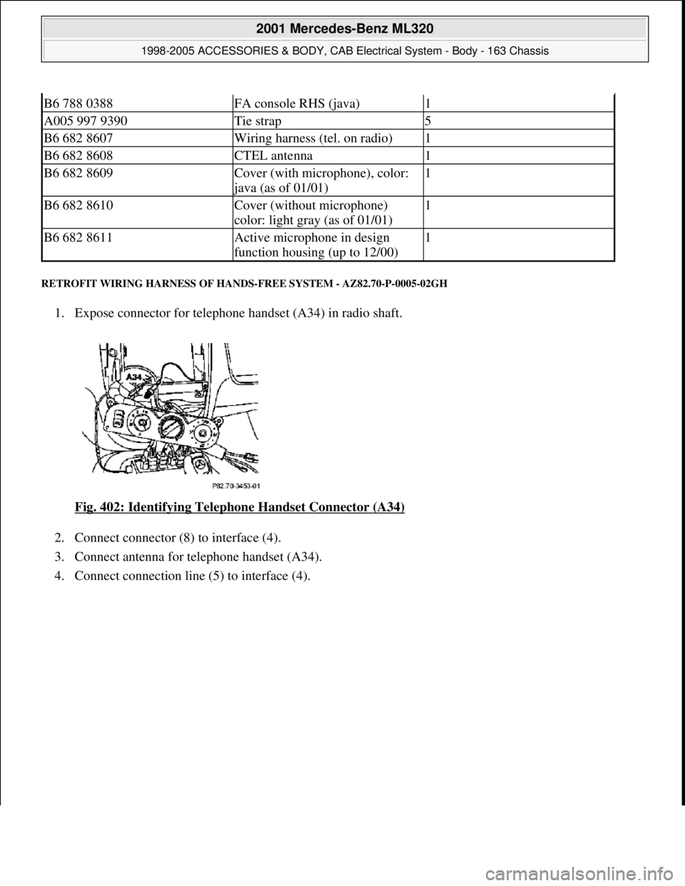
1. Expose connector for telephone handset (A34) in radio shaft.
Fig. 402: Identifying Telephone Handset Connector (A34)
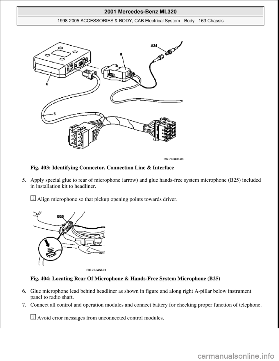
2. Connect connector (8) to interface (4).
3. Connect antenna for telephone handset (A34).
4. Connect connection line (5) to interface (4).
B6 788 0388FA console RHS (java)1
A005 997 9390Tie strap5
B6 682 8607Wiring harness (tel. on radio)1
B6 682 8608CTEL antenna1
B6 682 8609Cover (with microphone), color:
java (as of 01/01)
1
B6 682 8610Cover (without microphone)
color: light gray (as of 01/01)1
B6 682 8611Active microphone in design
function housing (up to 12/00)1
2001 Mercedes-Benz ML320
1998-2005 ACCESSORIES & BODY, CAB Electrical System - Body - 163 Chassis
me
Saturday, October 02, 2010 3:30:14 PMPage 456 © 2006 Mitchell Repair Information Company, LLC.
Page 1952 of 4133
Fig. 403: Identifying Connector, Connection Line & Interface
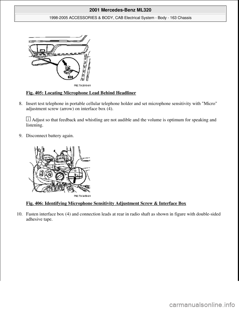
5. Apply special glue to rear of microphone (arrow) and glue hands-free system microphone (B25) included
in installation kit to headliner.
Align microphone so that pickup opening points towards driver.
Fig. 404: Locating Rear Of Microphone & Hands
-Free System Microphone (B25)
6. Glue microphone lead behind headliner as shown in figure and along right A-pillar below instrument
panel to radio shaft.
7. Connect all control and operation modules and connect battery for checking proper function of telephone.
Avoid error messa
ges from unconnected control modules.
2001 Mercedes-Benz ML320
1998-2005 ACCESSORIES & BODY, CAB Electrical System - Body - 163 Chassis
me
Saturday, October 02, 2010 3:30:14 PMPage 457 © 2006 Mitchell Repair Information Company, LLC.
Page 1953 of 4133
Fig. 405: Locating Microphone Lead Behind Headliner
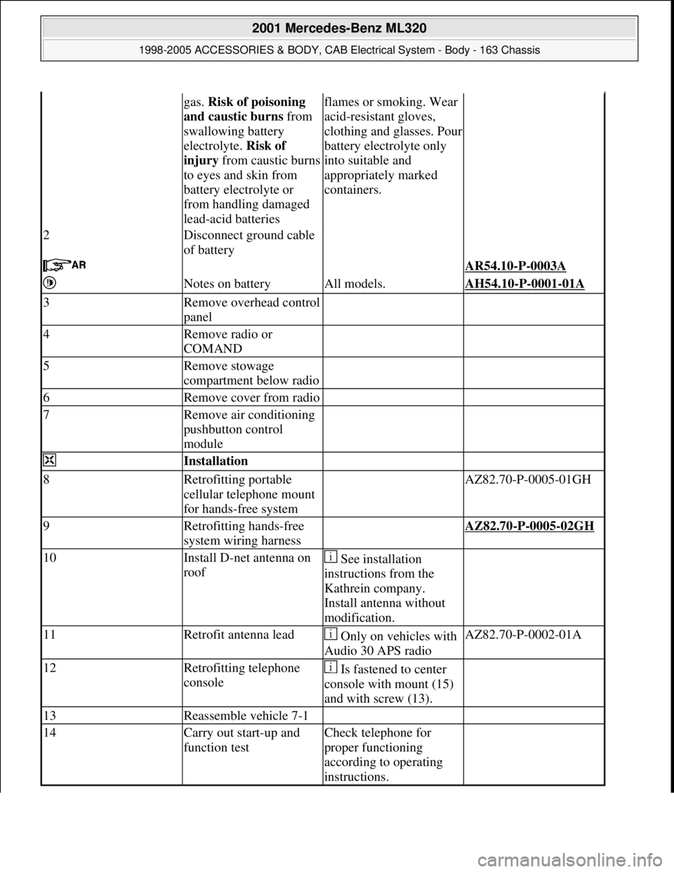
8. Insert test telephone in portable cellular telephone holder and set microphone sensitivity with "Micro"
adjustment screw (arrow) on interface box (4).
Adjust so that feedback and whistling are not audible and the volume is optimum for speaking and
listening.
9. Disconnect battery again.
Fig. 406: Identifying Microphone Sensitivity Adjustment Screw & Interface Box
10. Fasten interface box (4) and connection leads at rear in radio shaft as shown in figure with double-sided
adhesive tape.
2001 Mercedes-Benz ML320
1998-2005 ACCESSORIES & BODY, CAB Electrical System - Body - 163 Chassis
me
Saturday, October 02, 2010 3:30:14 PMPage 458 © 2006 Mitchell Repair Information Company, LLC.
Page 1955 of 4133
gas. Risk of poisoning
and caustic burns from
swallowing battery
electrolyte. Risk of
injury from caustic burns
to eyes and skin from
battery electrolyte or
from handling damaged
lead-acid batteriesflames or smoking. Wear
acid-resistant gloves,
clothing and glasses. Pour
battery electrolyte only
into suitable and
appropriately marked
containers.
2Disconnect ground cable
of battery
AR54.10-P-0003A
Notes on batteryAll models.AH54.10-P-0001-01A
3Remove overhead control
panel
4Remove radio or
COMAND
5Remove stowage
compartment below radio
6Remove cover from radio
7Remove air conditioning
pushbutton control
module
Installation
8Retrofitting portable
cellular telephone mount
for hands-free system AZ82.70-P-0005-01GH
9Retrofitting hands-free
system wiring harness AZ82.70-P-0005-02GH
10Install D-net antenna on
roof See installation
instructions from the
Kathrein company.
Install antenna without
modification.
11Retrofit antenna lead Only on vehicles with
Audio 30 APS radioAZ82.70-P-0002-01A
12Retrofitting telephone
console Is fastened to center
console with mount (15)
and with screw (13).
13Reassemble vehicle 7-1
14Carry out start-up and
function testCheck telephone for
proper functioning
according to operating
instructions.
2001 Mercedes-Benz ML320
1998-2005 ACCESSORIES & BODY, CAB Electrical System - Body - 163 Chassis
me
Saturday, October 02, 2010 3:30:14 PMPage 460 © 2006 Mitchell Repair Information Company, LLC.
Page 1956 of 4133
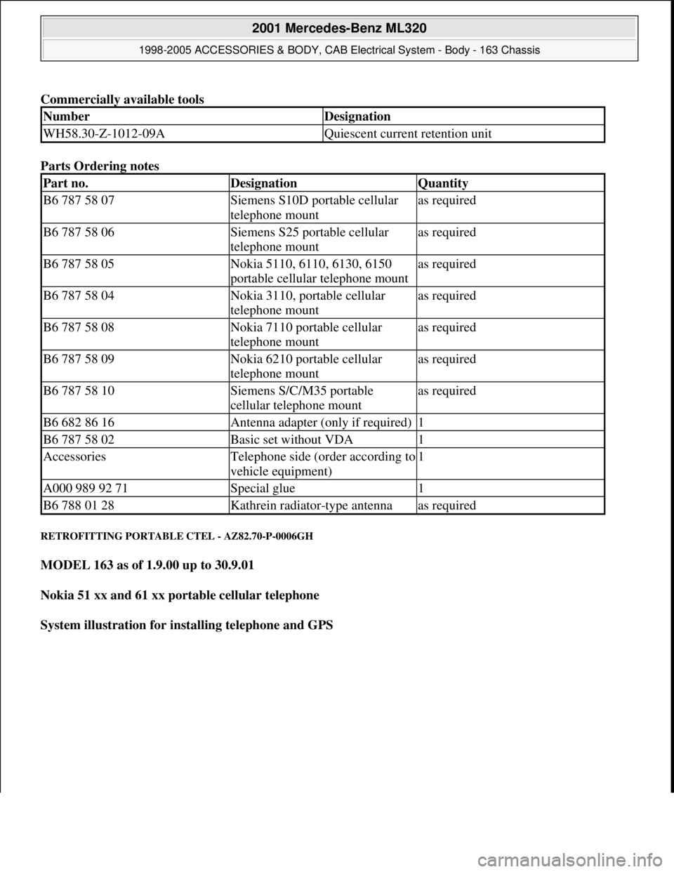
Commercially available tools
Parts Ordering notes
RETROFITTING PORTABLE CTEL - AZ82.70-P-0006GH
MODEL 163 as of 1.9.00 up to 30.9.01
Nokia 51 xx and 61 xx portable cellular telephone
System illustration for installing telephone and GPS
NumberDesignation
WH58.30-Z-1012-09AQuiescent current retention unit
Part no.DesignationQuantity
B6 787 58 07Siemens S10D portable cellular
telephone mountas required
B6 787 58 06Siemens S25 portable cellular
telephone mountas required
B6 787 58 05Nokia 5110, 6110, 6130, 6150
portable cellular telephone mountas required
B6 787 58 04Nokia 3110, portable cellular
telephone mountas required
B6 787 58 08Nokia 7110 portable cellular
telephone mountas required
B6 787 58 09Nokia 6210 portable cellular
telephone mountas required
B6 787 58 10Siemens S/C/M35 portable
cellular telephone mountas required
B6 682 86 16Antenna adapter (only if required)1
B6 787 58 02Basic set without VDA1
AccessoriesTelephone side (order according to
vehicle equipment)1
A000 989 92 71Special glue1
B6 788 01 28Kathrein radiator-type antennaas required
2001 Mercedes-Benz ML320
1998-2005 ACCESSORIES & BODY, CAB Electrical System - Body - 163 Chassis
me
Saturday, October 02, 2010 3:30:14 PMPage 461 © 2006 Mitchell Repair Information Company, LLC.
Page 1958 of 4133
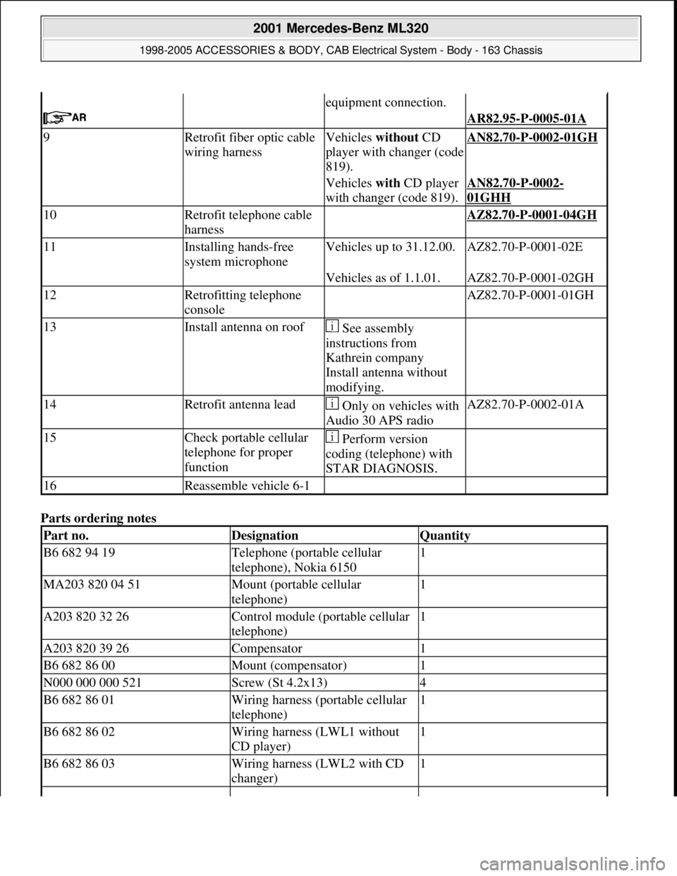
Parts ordering notes
equipment connection.
AR82.95-P-0005-01A
9Retrofit fiber optic cable
wiring harnessVehicles without CD
player with changer (code
819).AN82.70-P-0002-01GH
Vehicles with CD player
with changer (code 819).AN82.70-P-0002-
01GHH
10Retrofit telephone cable
harness AZ82.70-P-0001-04GH
11Installing hands-free
system microphoneVehicles up to 31.12.00.AZ82.70-P-0001-02E
Vehicles as of 1.1.01.AZ82.70-P-0001-02GH
12Retrofitting telephone
console AZ82.70-P-0001-01GH
13Install antenna on roof See assembly
instructions from
Kathrein company
Install antenna without
modifying.
14Retrofit antenna lead Only on vehicles with
Audio 30 APS radioAZ82.70-P-0002-01A
15Check portable cellular
telephone for proper
function Perform version
coding (telephone) with
STAR DIAGNOSIS.
16Reassemble vehicle 6-1
Part no.DesignationQuantity
B6 682 94 19Telephone (portable cellular
telephone), Nokia 61501
MA203 820 04 51Mount (portable cellular
telephone)1
A203 820 32 26Control module (portable cellular
telephone)1
A203 820 39 26Compensator1
B6 682 86 00Mount (compensator)1
N000 000 000 521Screw (St 4.2x13)4
B6 682 86 01Wiring harness (portable cellular
telephone)1
B6 682 86 02Wiring harness (LWL1 without
CD player)1
B6 682 86 03Wiring harness (LWL2 with CD
changer)1
2001 Mercedes-Benz ML320
1998-2005 ACCESSORIES & BODY, CAB Electrical System - Body - 163 Chassis
me
Saturday, October 02, 2010 3:30:14 PMPage 463 © 2006 Mitchell Repair Information Company, LLC.
Page 1959 of 4133
REMOVAL & INSTALLATION
INSTALLING LARGER WASHER FLUID RESERVOIR - SM82.35-P-0002GH
MODELS 163.113/136/154/172
with 5 I container
The 5 I washer fluid reservoir has been replaced by a 7.6 I container. If a 5 l container is replaced, then the
following modifications must be made.
This modification should ONLY be performed following a customer complaint.
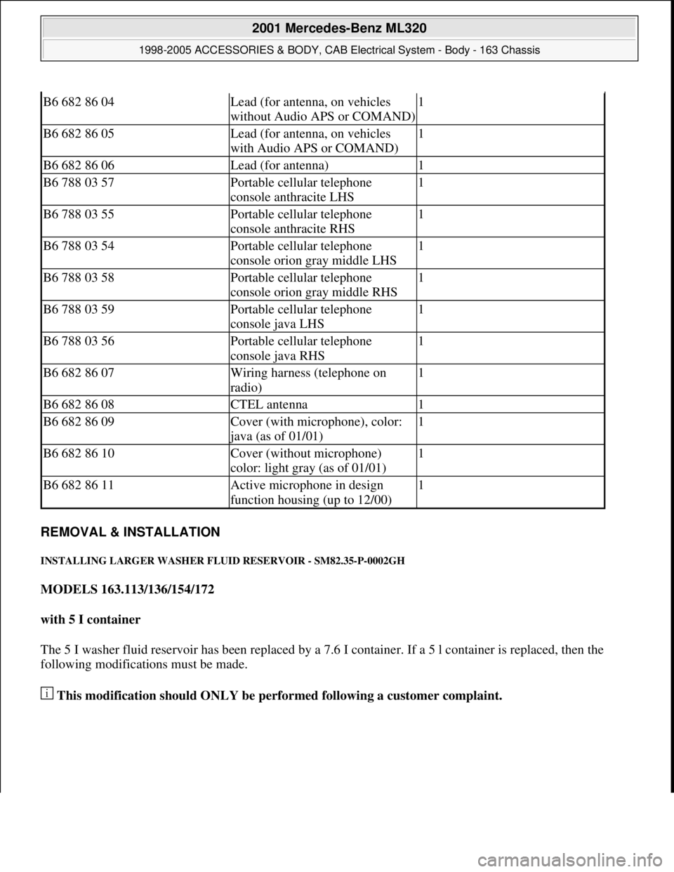
B6 682 86 04Lead (for antenna, on vehicles
without Audio APS or COMAND)1
B6 682 86 05Lead (for antenna, on vehicles
with Audio APS or COMAND)1
B6 682 86 06Lead (for antenna)1
B6 788 03 57Portable cellular telephone
console anthracite LHS1
B6 788 03 55Portable cellular telephone
console anthracite RHS1
B6 788 03 54Portable cellular telephone
console orion gray middle LHS1
B6 788 03 58Portable cellular telephone
console orion gray middle RHS1
B6 788 03 59Portable cellular telephone
console java LHS1
B6 788 03 56Portable cellular telephone
console java RHS1
B6 682 86 07Wiring harness (telephone on
radio)1
B6 682 86 08CTEL antenna1
B6 682 86 09Cover (with microphone), color:
java (as of 01/01)
1
B6 682 86 10Cover (without microphone)
color: light gray (as of 01/01)1
B6 682 86 11Active microphone in design
function housing (up to 12/00)1
2001 Mercedes-Benz ML320
1998-2005 ACCESSORIES & BODY, CAB Electrical System - Body - 163 Chassis
me
Saturday, October 02, 2010 3:30:14 PMPage 464 © 2006 Mitchell Repair Information Company, LLC.
Page 2037 of 4133
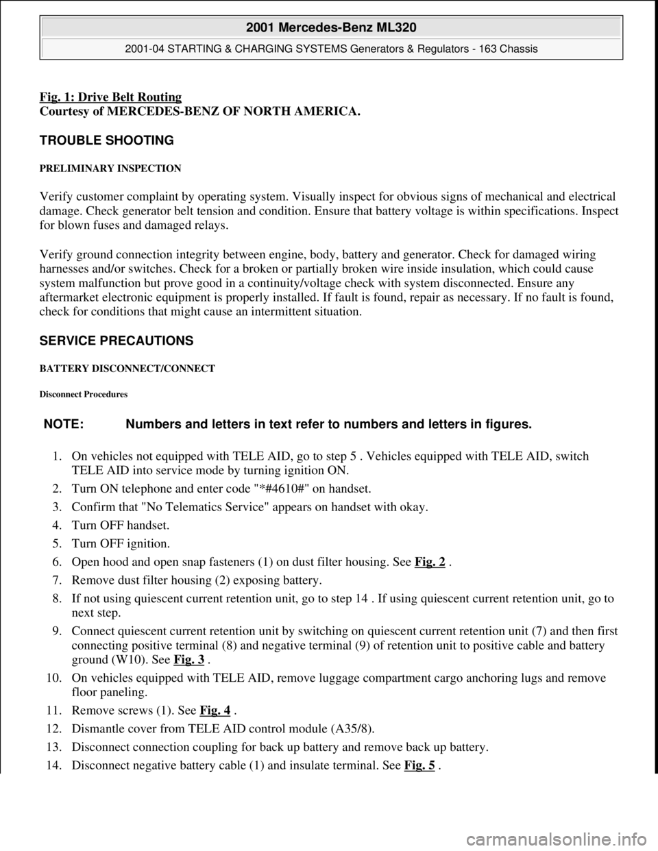
Fig. 1: Drive Belt Routing
Courtesy of MERCEDES-BENZ OF NORTH AMERICA.
TROUBLE SHOOTING
PRELIMINARY INSPECTION
Verify customer complaint by operating system. Visually inspect for obvious signs of mechanical and electrical
damage. Check generator belt tension and condition. Ensure that battery voltage is within specifications. Inspect
for blown fuses and damaged relays.
Verify ground connection integrity between engine, body, battery and generator. Check for damaged wiring
harnesses and/or switches. Check for a broken or partially broken wire inside insulation, which could cause
system malfunction but prove good in a continuity/voltage check with system disconnected. Ensure any
aftermarket electronic equipment is properly installed. If fault is found, repair as necessary. If no fault is found,
check for conditions that might cause an intermittent situation.
SERVICE PRECAUTIONS
BATTERY DISCONNECT/CONNECT
Disconnect Procedures
1. On vehicles not equipped with TELE AID, go to step 5 . Vehicles equipped with TELE AID, switch
TELE AID into service mode by turning ignition ON.
2. Turn ON telephone and enter code "*#4610#" on handset.
3. Confirm that "No Telematics Service" appears on handset with okay.
4. Turn OFF handset.
5. Turn OFF ignition.
6. Open hood and open snap fasteners (1) on dust filter housing. See Fig. 2
.
7. Remove dust filter housing (2) exposing battery.
8. If not using quiescent current retention unit, go to step 14 . If using quiescent current retention unit, go to
next step.
9. Connect quiescent current retention unit by switching on quiescent current retention unit (7) and then first
connecting positive terminal (8) and negative terminal (9) of retention unit to positive cable and battery
ground (W10). See Fig. 3
.
10. On vehicles equipped with TELE AID, remove luggage compartment cargo anchoring lugs and remove
floor paneling.
11. Remove screws (1). See Fig. 4
.
12. Dismantle cover from TELE AID control module (A35/8).
13. Disconnect connection coupling for back up battery and remove back up battery.
14. Disconnect ne
gative battery cable (1) and insulate terminal. See Fig. 5. NOTE: Numbers and letters in text refer to numbers and letters in figures.
2001 Mercedes-Benz ML320
2001-04 STARTING & CHARGING SYSTEMS Generators & Regulators - 163 Chassis
me
Saturday, October 02, 2010 3:20:31 PMPage 3 © 2006 Mitchell Repair Information Company, LLC.