1997 MERCEDES-BENZ ML320 battery location
[x] Cancel search: battery locationPage 1741 of 4133
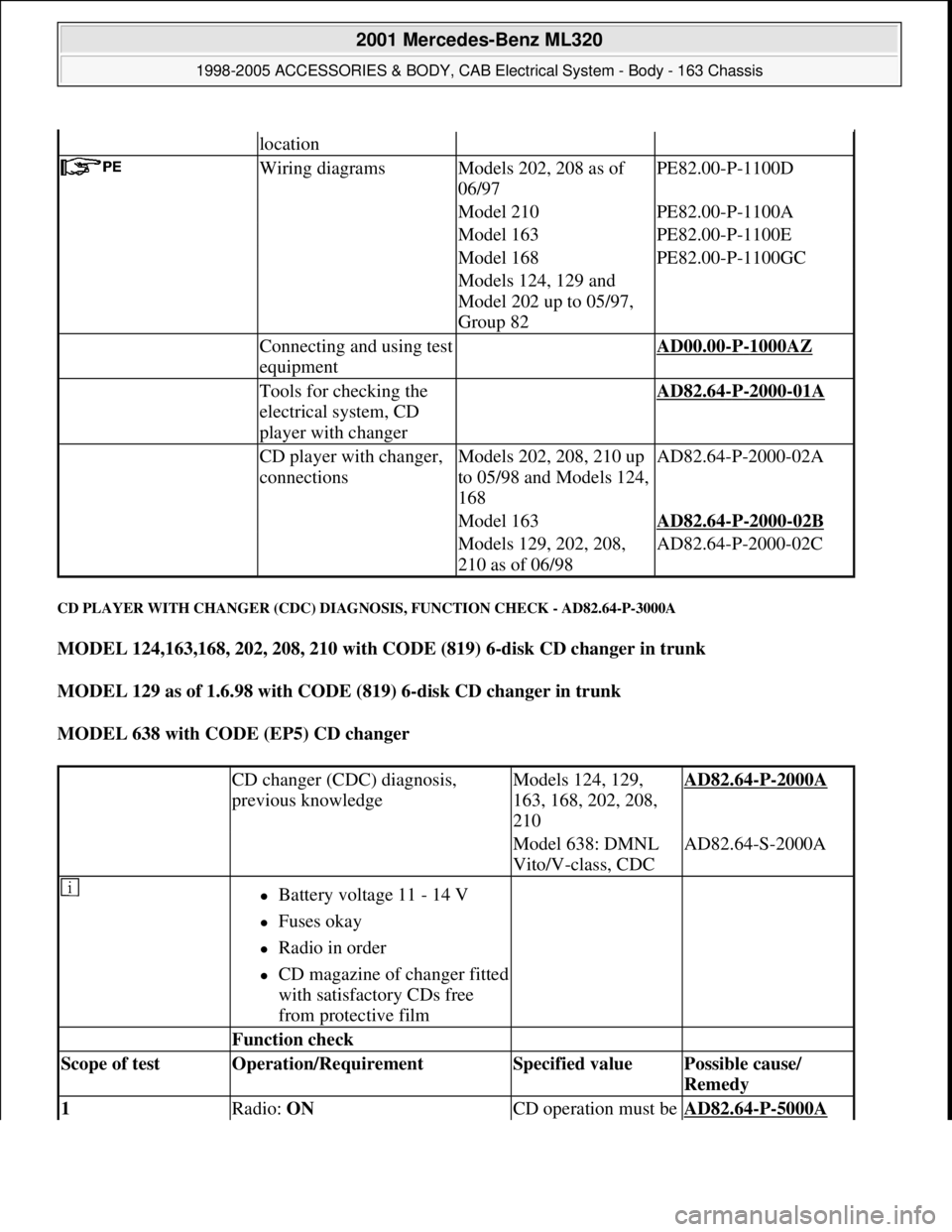
CD PLAYER WITH CHANGER (CDC) DIAGNOSIS, FUNCTION CHECK - AD82.64-P-3000A
MODEL 124,163,168, 202, 208, 210 with CODE (819) 6-disk CD changer in trunk
MODEL 129 as of 1.6.98 with CODE (819) 6-disk CD changer in trunk
MODEL 638 with CODE (EP5) CD changer
location
Wiring diagramsModels 202, 208 as of
06/97PE82.00-P-1100D
Model 210PE82.00-P-1100A
Model 163PE82.00-P-1100E
Model 168PE82.00-P-1100GC
Models 124, 129 and
Model 202 up to 05/97,
Group 82
Connecting and using test
equipment AD00.00-P-1000AZ
Tools for checking the
electrical system, CD
player with changer AD82.64-P-2000-01A
CD player with changer,
connectionsModels 202, 208, 210 up
to 05/98 and Models 124,
168AD82.64-P-2000-02A
Model 163AD82.64-P-2000-02B
Models 129, 202, 208,
210 as of 06/98AD82.64-P-2000-02C
CD changer (CDC) diagnosis,
previous knowledgeModels 124, 129,
163, 168, 202, 208,
210AD82.64-P-2000A
Model 638: DMNL
Vito/V-class, CDCAD82.64-S-2000A
Battery voltage 11 - 14 V
Fuses okay
Radio in order
CD magazine of changer fitted
with satisfactory CDs free
from protective film
Function check
Scope of test Operation/Requirement Specified value Possible cause/
Remedy
1 Radio: ON CD operation must be AD82.64-P-5000A
2001 Mercedes-Benz ML320
1998-2005 ACCESSORIES & BODY, CAB Electrical System - Body - 163 Chassis
me
Saturday, October 02, 2010 3:30:08 PMPage 246 © 2006 Mitchell Repair Information Company, LLC.
Page 2146 of 4133
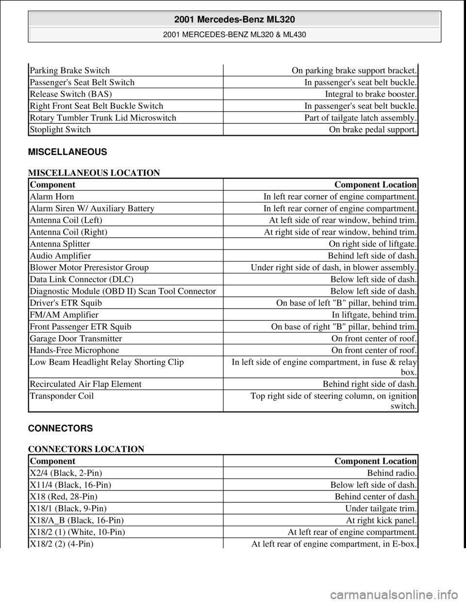
MISCELLANEOUS
MISCELLANEOUS LOCATION
CONNECTORS
CONNECTORS LOCATION
Parking Brake SwitchOn parking brake support bracket.
Passenger's Seat Belt SwitchIn passenger's seat belt buckle.
Release Switch (BAS)Integral to brake booster.
Right Front Seat Belt Buckle SwitchIn passenger's seat belt buckle.
Rotary Tumbler Trunk Lid MicroswitchPart of tailgate latch assembly.
Stoplight SwitchOn brake pedal support.
ComponentComponent Location
Alarm HornIn left rear corner of engine compartment.
Alarm Siren W/ Auxiliary BatteryIn left rear corner of engine compartment.
Antenna Coil (Left)At left side of rear window, behind trim.
Antenna Coil (Right)At right side of rear window, behind trim.
Antenna SplitterOn right side of liftgate.
Audio AmplifierBehind left side of dash.
Blower Motor Preresistor GroupUnder right side of dash, in blower assembly.
Data Link Connector (DLC)Below left side of dash.
Diagnostic Module (OBD II) Scan Tool ConnectorBelow left side of dash.
Driver's ETR SquibOn base of left "B" pillar, behind trim.
FM/AM AmplifierIn liftgate, behind trim.
Front Passenger ETR SquibOn base of right "B" pillar, behind trim.
Garage Door TransmitterOn front center of roof.
Hands-Free MicrophoneOn front center of roof.
Low Beam Headlight Relay Shorting ClipIn left side of engine compartment, in fuse & relay
box.
Recirculated Air Flap ElementBehind right side of dash.
Transponder CoilTop right side of steering column, on ignition
switch.
ComponentComponent Location
X2/4 (Black, 2-Pin)Behind radio.
X11/4 (Black, 16-Pin)Below left side of dash.
X18 (Red, 28-Pin)Behind center of dash.
X18/1 (Black, 9-Pin)Under tailgate trim.
X18/A_B (Black, 16-Pin)At right kick panel.
X18/2 (1) (White, 10-Pin)At left rear of engine compartment.
X18/2 (2) (4-Pin)At left rear of engine compartment, in E-box.
2001 Mercedes-Benz ML320
2001 MERCEDES-BENZ ML320 & ML430
me
Saturday, October 02, 2010 3:21:17 PMPage 6 © 2006 Mitchell Repair Information Company, LLC.
Page 3347 of 4133
Whenever the system is opened, the fluid reservoir should be replaced because of the water which has
collected there in the meantime.
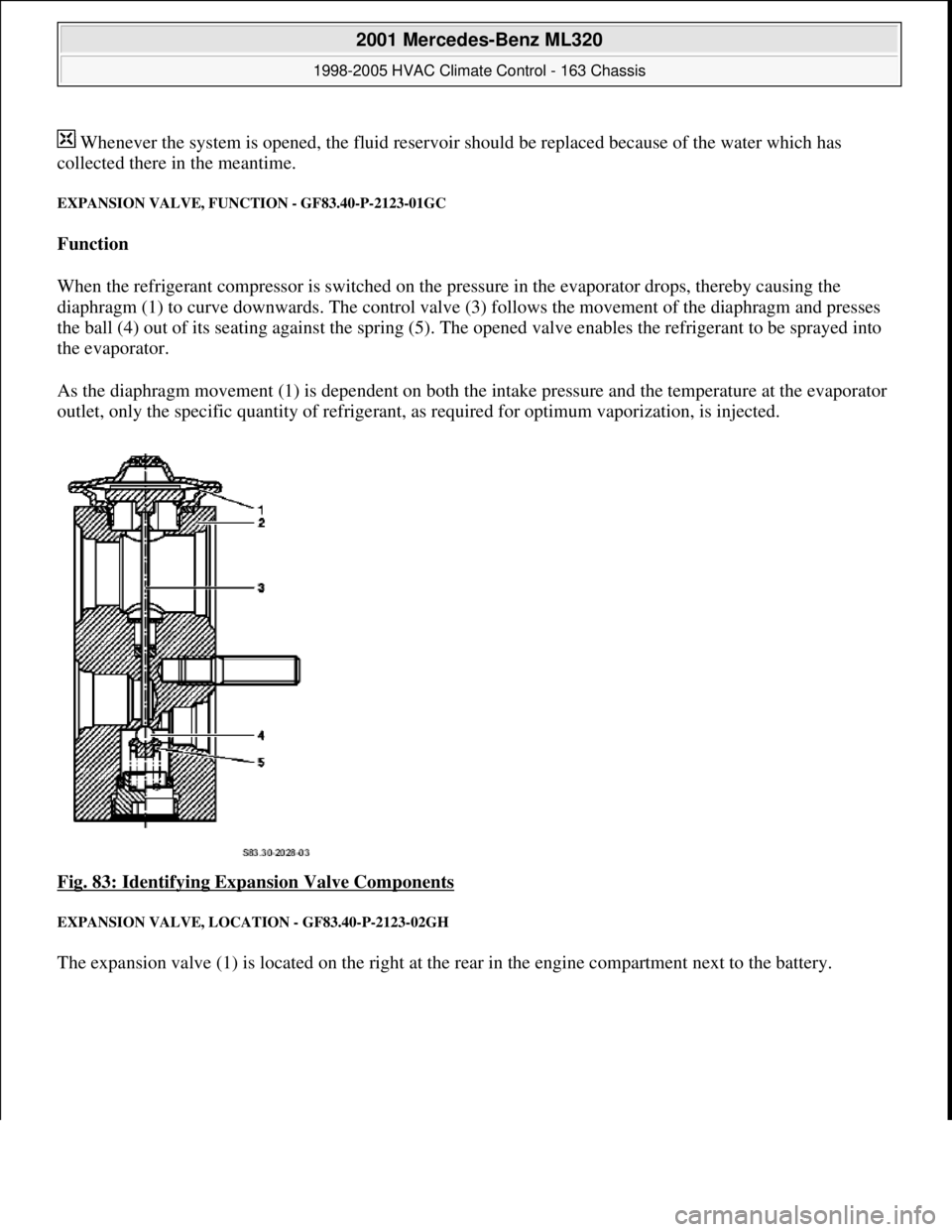
EXPANSION VALVE, FUNCTION - GF83.40-P-2123-01GC
Function
When the refrigerant compressor is switched on the pressure in the evaporator drops, thereby causing the
diaphragm (1) to curve downwards. The control valve (3) follows the movement of the diaphragm and presses
the ball (4) out of its seating against the spring (5). The opened valve enables the refrigerant to be sprayed into
the evaporator.
As the diaphragm movement (1) is dependent on both the intake pressure and the temperature at the evaporator
outlet, only the specific quantity of refrigerant, as required for optimum vaporization, is injected.
Fig. 83: Identifying Expansion Valve Components
EXPANSION VALVE, LOCATION - GF83.40-P-2123-02GH
The expansion valve (1) is located on the right at the rear in the engine compartment next to the battery.
2001 Mercedes-Benz ML320
1998-2005 HVAC Climate Control - 163 Chassis
me
Saturday, October 02, 2010 3:23:16 PMPage 103 © 2006 Mitchell Repair Information Company, LLC.
Page 3397 of 4133
OFF . To this end the system uses the residual heat of the engine. The residual engine heat is dissipated to the
coolant and routed through the heat exchanger with the aid of the heating water circulation pump. The air drawn
in by the blower motor is routed around the heat exchanger, whereby it is then warmed up. The heated air is
then routed over the air outlets into the passenger compartment.
The residual engine heat utilization system can only be used when the ignition is switched OFF.
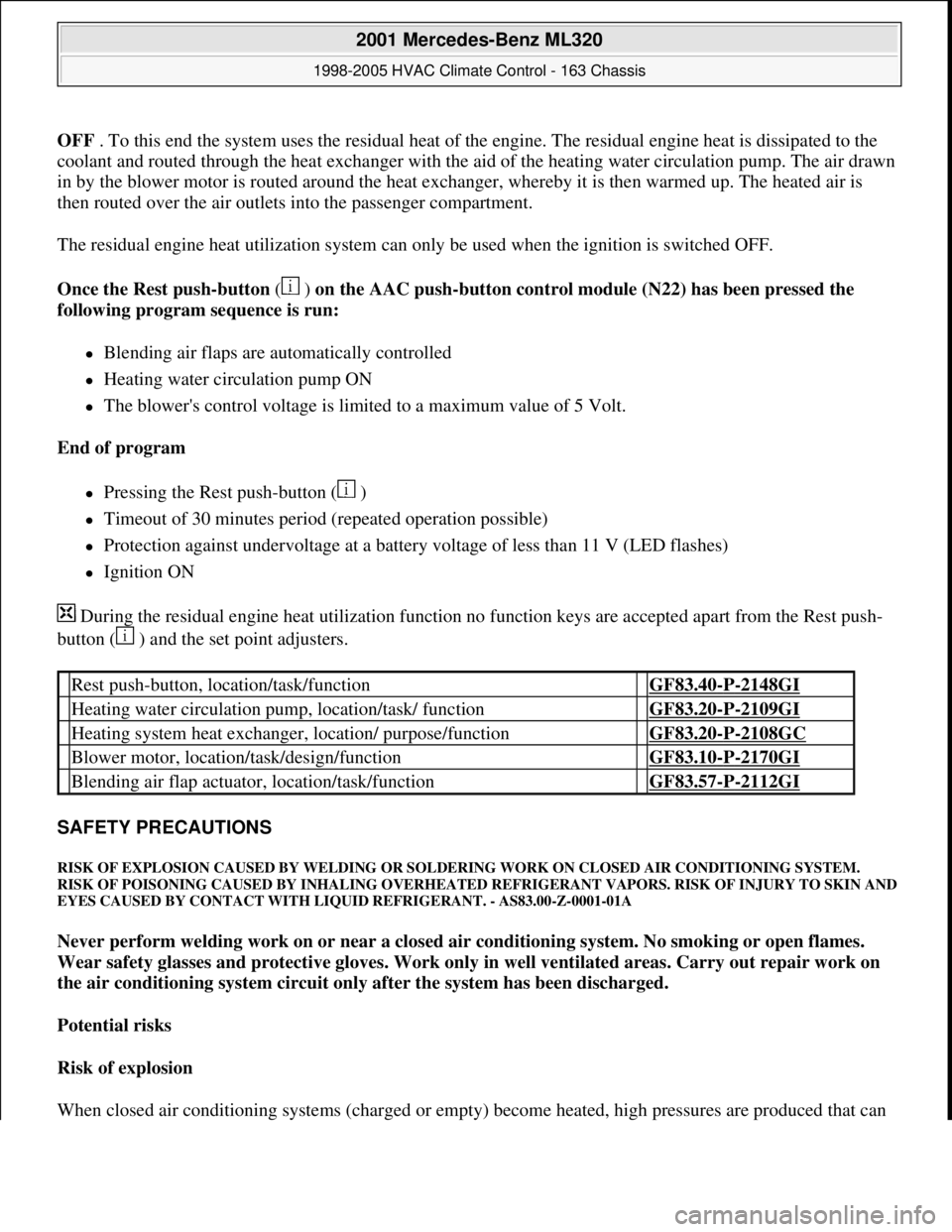
Once the Rest push-button ( ) on the AAC push-button control module (N22) has been pressed the
following program sequence is run:
Blending air flaps are automatically controlled
Heating water circulation pump ON
The blower's control voltage is limited to a maximum value of 5 Volt.
End of program
Pressing the Rest push-button ( )
Timeout of 30 minutes period (repeated operation possible)
Protection against undervoltage at a battery voltage of less than 11 V (LED flashes)
Ignition ON
During the residual engine heat utilization function no function keys are accepted apart from the Rest push-
button ( ) and the set point adjusters.
SAFETY PRECAUTIONS
RISK OF EXPLOSION CAUSED BY WELDING OR SOLDERING WORK ON CLOSED AIR CONDITIONING SYSTEM.
RISK OF POISONING CAUSED BY INHALING OVERHEATED REFRIGERANT VAPORS. RISK OF INJURY TO SKIN AND
EYES CAUSED BY CONTACT WITH LIQUID REFRIGERANT. - AS83.00-Z-0001-01A
Never perform welding work on or near a closed air conditioning system. No smoking or open flames.
Wear safety glasses and protective gloves. Work only in well ventilated areas. Carry out repair work on
the air conditioning system circuit only after the system has been discharged.
Potential risks
Risk of explosion
When closed air conditionin
g systems (charged or empty) become heated, high pressures are produced that can
Rest push-button, location/task/function GF83.40-P-2148GI
Heating water circulation pump, location/task/ function GF83.20-P-2109GI
Heating system heat exchanger, location/ purpose/function GF83.20-P-2108GC
Blower motor, location/task/design/function GF83.10-P-2170GI
Blending air flap actuator, location/task/function GF83.57-P-2112GI
2001 Mercedes-Benz ML320
1998-2005 HVAC Climate Control - 163 Chassis
me
Saturday, October 02, 2010 3:23:17 PMPage 153 © 2006 Mitchell Repair Information Company, LLC.
Page 3475 of 4133
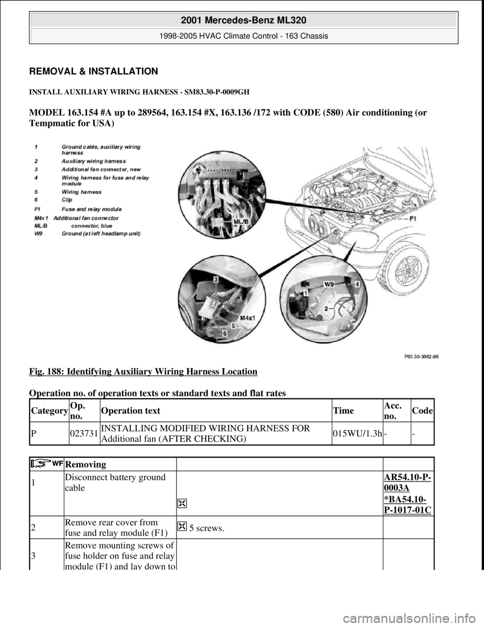
REMOVAL & INSTALLATION
INSTALL AUXILIARY WIRING HARNESS - SM83.30-P-0009GH
MODEL 163.154 #A up to 289564, 163.154 #X, 163.136 /172 with CODE (580) Air conditioning (or
Tempmatic for USA)
Fig. 188: Identifying Auxiliary Wiring Harness Location
Operation no. of operation texts or standard texts and flat rates
CategoryOp.
no.Operation textTimeAcc.
no.Code
P023731INSTALLING MODIFIED WIRING HARNESS FOR
Additional fan (AFTER CHECKING)015WU/1.3h--
Removing
1Disconnect battery ground
cable AR54.10-P-
0003A
*BA54.10-
P-1017-01C
2Remove rear cover from
fuse and relay module (F1) 5 screws.
3
Remove mounting screws of
fuse holder on fuse and relay
module (F1) and lay down to
2001 Mercedes-Benz ML320
1998-2005 HVAC Climate Control - 163 Chassis
me
Saturday, October 02, 2010 3:23:19 PMPage 231 © 2006 Mitchell Repair Information Company, LLC.
Page 3477 of 4133
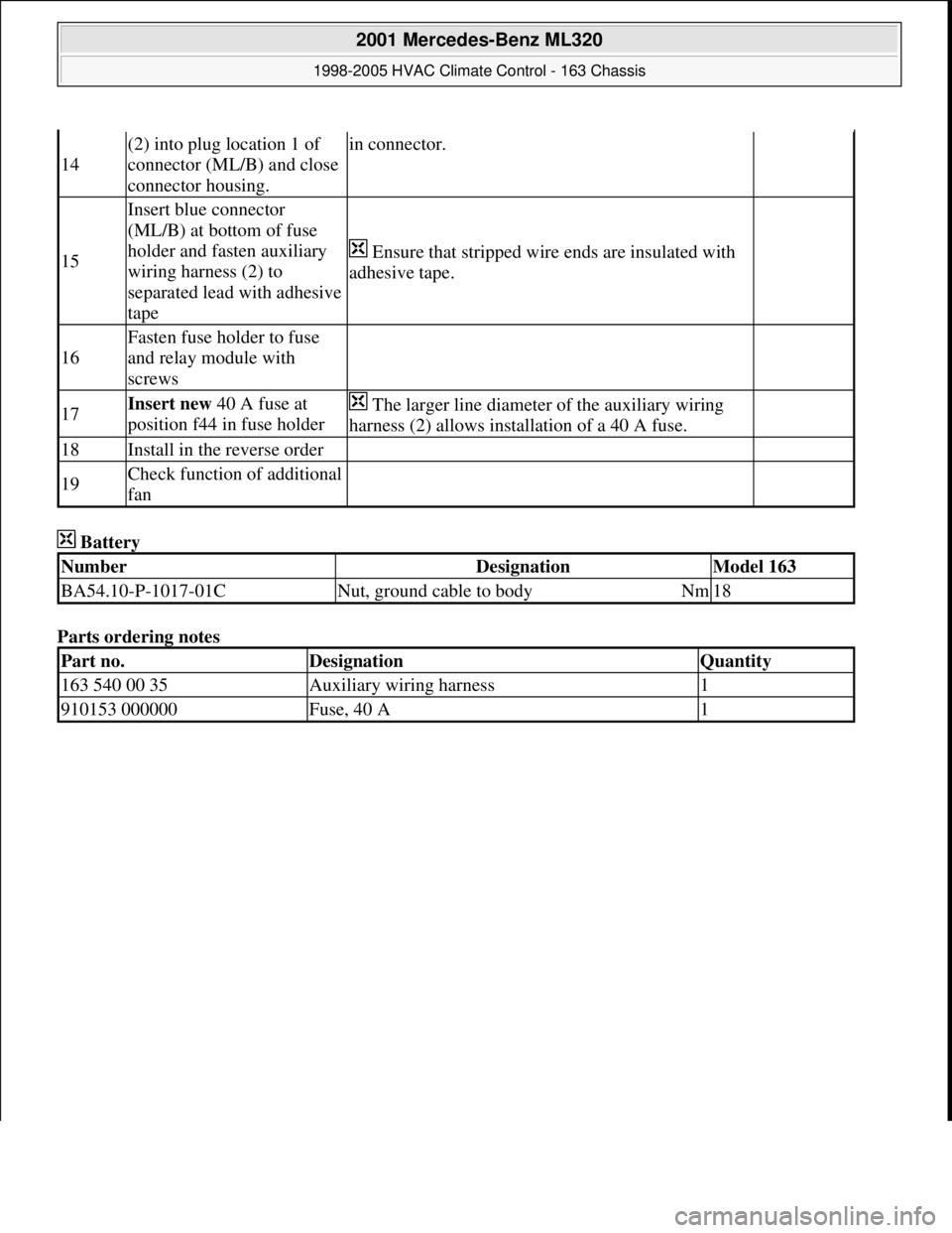
Battery
Parts ordering notes
14
(2) into plug location 1 of
connector (ML/B) and close
connector housing.in connector.
15
Insert blue connector
(ML/B) at bottom of fuse
holder and fasten auxiliary
wiring harness (2) to
separated lead with adhesive
tape
Ensure that stripped wire ends are insulated with
adhesive tape.
16
Fasten fuse holder to fuse
and relay module with
screws
17Insert new 40 A fuse at
position f44 in fuse holder The larger line diameter of the auxiliary wiring
harness (2) allows installation of a 40 A fuse.
18Install in the reverse order
19Check function of additional
fan
NumberDesignationModel 163
BA54.10-P-1017-01CNut, ground cable to bodyNm18
Part no.DesignationQuantity
163 540 00 35Auxiliary wiring harness1
910153 000000Fuse, 40 A1
2001 Mercedes-Benz ML320
1998-2005 HVAC Climate Control - 163 Chassis
me
Saturday, October 02, 2010 3:23:19 PMPage 233 © 2006 Mitchell Repair Information Company, LLC.
Page 3485 of 4133

Rims
D
When changing wheels, for instance, when replacing steel
wheels with light-alloy rims, ensure that the wheel bolts
required for the spare wheel are stored in a clearly visible
location.
D
Since December 1994 models 202 and 124 with special
equipment light alloy disk wheels, are supplied with a sheet
steel spare wheel instead of a light alloy spare wheel. The
necessary wheel bolts are included with the steel spare wheel.
D
Only use approved Mercedes-Benz rims of the same version.
D
Reinforced steel rims are identified by a sticker on the wheel
disc.
D
The wheel bolts on steel and light-alloy rims should always be
tightened to the specified tightening torque using a torque
wrench.
It is not necessary to retorque the lug bolts after approximately
100 to 500 km.
D
The seat for the tire bead must display no corrosion marks.
D
Before inserting a new rubber valve, clean the contact surfaces
on the disk wheel.
On sheet steel-disk wheel wheel trims must be fitted to support
the rubber valve.
Damaged or deformed rims must not be repaired.
Tire pressure monitor
D
Before replacing a tire, check the date of manufacturer of the
wheel sensor: wheel sensors which are more than 5 years old
must be replaced.
D
Use STAR DIAGNOSIS to read out the actual values of the tire
pressure monitor. Check the remaining life of the wheel sensor
battery, replace the wheel sensor if necessary.
Copyright DaimlerChrysler AG 06.07.2006 CD-Ausgabe G/10/04 . This WIS print-out will not be recorde
d by Modification services.
Page 2
Page 3528 of 4133
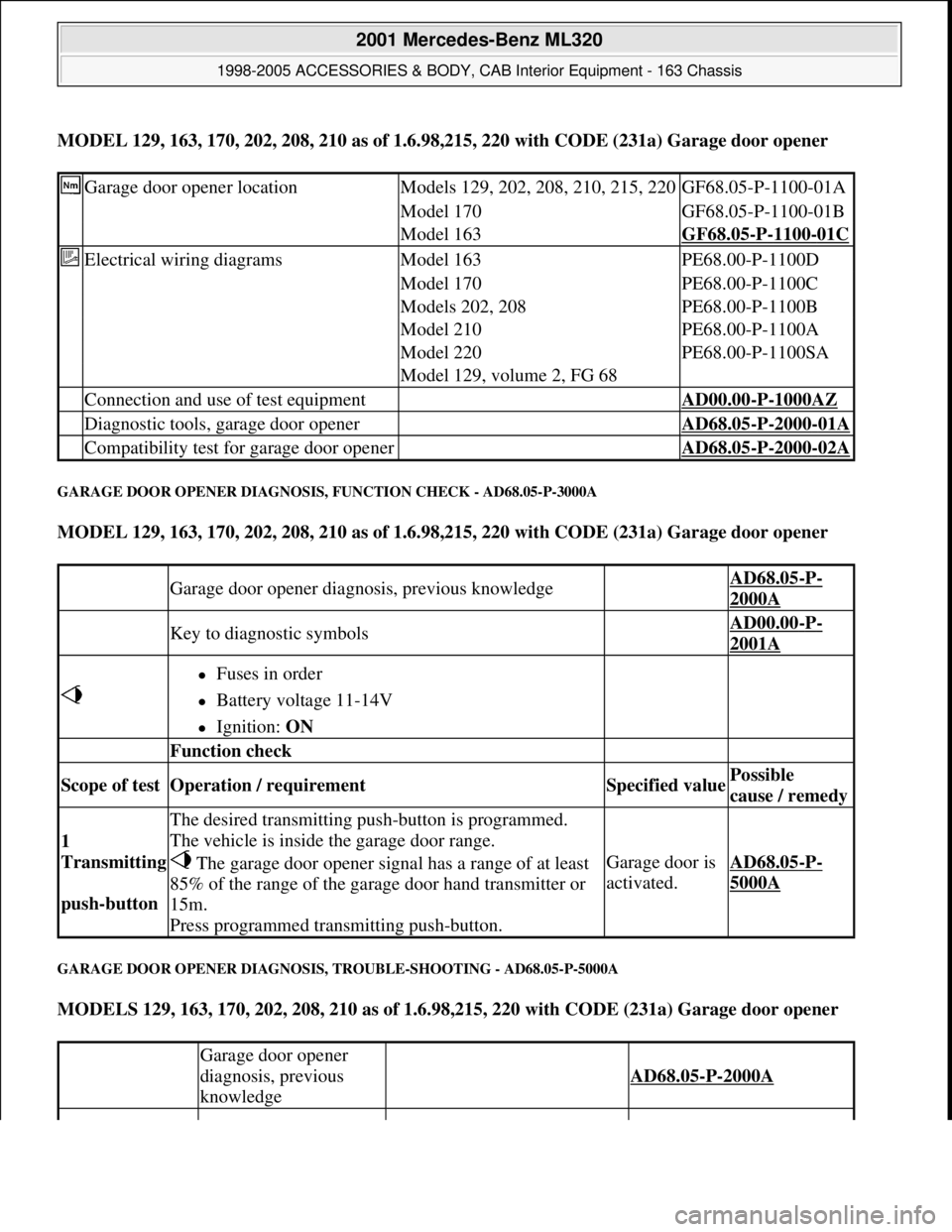
MODEL 129, 163, 170, 202, 208, 210 as of 1.6.98,215, 220 with CODE (231a) Garage door opener
GARAGE DOOR OPENER DIAGNOSIS, FUNCTION CHECK - AD68.05-P-3000A
MODEL 129, 163, 170, 202, 208, 210 as of 1.6.98,215, 220 with CODE (231a) Garage door opener
GARAGE DOOR OPENER DIAGNOSIS, TROUBLE-SHOOTING - AD68.05-P-5000A
MODELS 129, 163, 170, 202, 208, 210 as of 1.6.98,215, 220 with CODE (231a) Garage door opener
Garage door opener locationModels 129, 202, 208, 210, 215, 220GF68.05-P-1100-01A
Model 170GF68.05-P-1100-01B
Model 163GF68.05-P-1100-01C
Electrical wiring diagramsModel 163PE68.00-P-1100D
Model 170PE68.00-P-1100C
Models 202, 208PE68.00-P-1100B
Model 210PE68.00-P-1100A
Model 220PE68.00-P-1100SA
Model 129, volume 2, FG 68
Connection and use of test equipment AD00.00-P-1000AZ
Diagnostic tools, garage door opener AD68.05-P-2000-01A
Compatibility test for garage door opener AD68.05-P-2000-02A
Garage door opener diagnosis, previous knowledge AD68.05-P-
2000A
Key to diagnostic symbols AD00.00-P-
2001A
Fuses in order
Battery voltage 11-14V
Ignition: ON
Function check
Scope of test Operation / requirement Specified value Possible
cause / remedy
1
Transmitting
push-button
The desired transmitting push-button is programmed.
The vehicle is inside the garage door range.
The garage door opener signal has a range of at least
85% of the range of the garage door hand transmitter or
15m.
Press programmed transmitting push-button.
Garage door is
activated.AD68.05-P-
5000A
Garage door opener
diagnosis, previous
knowledge
AD68.05-P-2000A
2001 Mercedes-Benz ML320
1998-2005 ACCESSORIES & BODY, CAB Interior Equipment - 163 Chassis
me
Saturday, October 02, 2010 3:35:21 PMPage 10 © 2006 Mitchell Repair Information Company, LLC.