Page 3875 of 4133
Fig. 20: Identifying Accelerator Pedal Components
REMOVE/INSTALL ELECTRONIC ACCELERATOR ACTUATOR WITH FLAP CONNECTION - AR30.20-P-1262A
MODEL 129, 163, 170, 171, 202, 203, 208, 209, 210, 215, 220, 230, 463 (except, 215.376 /378 /379,
220.176 /876 /178 /878 /179, 230.476 /477 /479)
Mass air flow sensor removed
Shown on engine 112 in model 210
Remove, Install
1Detach control cable (30) at accelerator pedal
(24) (arrow) Pull out expanding wedge bolt (24/1) in
order to do this.
2Unscrew screws (34/2) from accelerator pedal
(24)
3Remove accelerator pedal (24)
4Install in the reverse order
2001 Mercedes-Benz ML320
1998-2005 ACCESSORIES & BODY CAB Throttle Control, Speed Control Systems - 163 Chassis
me
Saturday, October 02, 2010 3:36:28 PMPage 35 © 2006 Mitchell Repair Information Company, LLC.
Page 3876 of 4133
Fig. 21: Identifying Electronic Accelerator Actuator With Flap Connection
MAINTENANCE
LUBRICATE JOINTS OF ENGINE CONTROL SYSTEM, CHECK JOINTS FOR FREEDOM OF MOVEMENT AND PROPER
SEATING - AP30.10-P-3022GH
ENGINE 112.942 /970, 113.942 /965 /981, 612.963, 628.963 in MODEL 163
Remove/install
1Detach crankcase vent line (1/2) from intake manifold
(19)
2Disconnect electrical connector (arrow) Pull catch backwards.
3Remove bolts (8/1) and throttle valve actuator (M16/6) Installation: Replace O-ring
(8/2).
4Install in the reverse order
2001 Mercedes-Benz ML320
1998-2005 ACCESSORIES & BODY CAB Throttle Control, Speed Control Systems - 163 Chassis
me
Saturday, October 02, 2010 3:36:28 PMPage 36 © 2006 Mitchell Repair Information Company, LLC.
Page 3877 of 4133

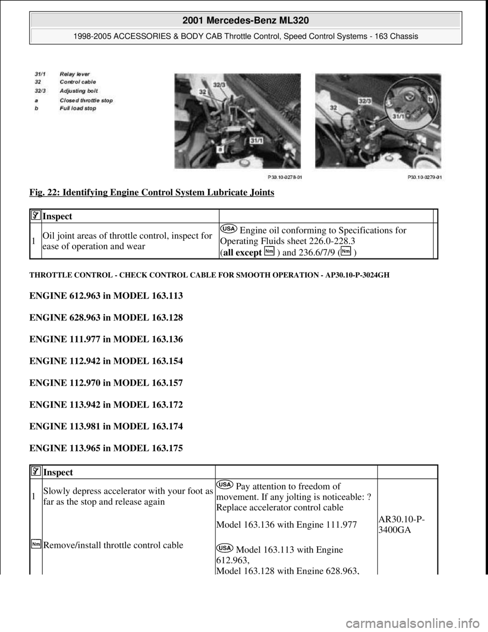
Fig. 22: Identifying Engine Control System Lubricate Joints
THROTTLE CONTROL - CHECK CONTROL CABLE FOR SMOOTH OPERATION - AP30.10-P-3024GH
ENGINE 612.963 in MODEL 163.113
ENGINE 628.963 in MODEL 163.128
ENGINE 111.977 in MODEL 163.136
ENGINE 112.942 in MODEL 163.154
ENGINE 112.970 in MODEL 163.157
ENGINE 113.942 in MODEL 163.172
ENGINE 113.981 in MODEL 163.174
ENGINE 113.965 in MODEL 163.175
Inspect
1Oil joint areas of throttle control, inspect for
ease of operation and wear Engine oil conforming to Specifications for
Operating Fluids sheet 226.0-228.3
(all except ) and 236.6/7/9 ( )
Inspect
1Slowly depress accelerator with your foot as
far as the stop and release again Pay attention to freedom of
movement. If any jolting is noticeable: ?
Replace accelerator control cable
Remove/install throttle control cable
Model 163.136 with Engine 111.977AR30.10-P-
3400GA
Model 163.113 with Engine
612.963,
Model 163.128 with Engine 628.963,
2001 Mercedes-Benz ML320
1998-2005 ACCESSORIES & BODY CAB Throttle Control, Speed Control Systems - 163 Chassis
me
Saturday, October 02, 2010 3:36:28 PMPage 37 © 2006 Mitchell Repair Information Company, LLC.
Page 3878 of 4133
Model 163.154 with Engine 112.942,
Model 163.157 with Engine 112.970,
Model 163.172 with Engine 113.942,
Model 163.174 with Engine 113.981,
Model 163.175 with Engine 113.965
AR30.10-P-
3400GI
2001 Mercedes-Benz ML320
1998-2005 ACCESSORIES & BODY CAB Throttle Control, Speed Control Systems - 163 Chassis
me
Saturday, October 02, 2010 3:36:28 PMPage 38 © 2006 Mitchell Repair Information Company, LLC.
Page 3883 of 4133

2001-04 STARTING & CHARGING SYSTEMS Starters - 163 Chassis
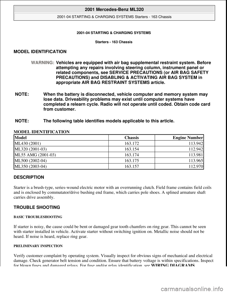
MODEL IDENTIFICATION
MODEL IDENTIFICATION
DESCRIPTION
Starter is a brush-type, series-wound el ectric motor with an overrunning clutch. Field frame contains field coils
and is enclosed by commutator/drive bushing end frame, which carries pole shoes. A splined armature shaft
carries drive assembly.
TROUBLE SHOOTING
BASIC TROUBLESHOOTING
If starter is noisy, the cause could be bent or damaged gear tooth chamfers on ring gear. This cannot be seen
with starter installed in ve hicle. Activate starter without switching ignition on. Me tallic noise should not be
heard. If noise is he ard, replace ring gear.
PRELIMINARY INSPECTION
Verify customer complaint by operating system. Visually inspect for obvious signs of mechanical and electrical
damage. Check generator belt tension and condition. Ensure that battery voltage is within specifications. Inspect
for blown fuses and damaged relays. For fuse and/or relay identification, see WIRING DIAGRAMS
.
WARNING:
Vehicles are equipped with air bag supplemental restraint system. Before
attempting any repairs involving steer ing column, instrument panel or
related components, see SERVICE PRECAUTIONS (or AIR BAG SAFETY
PRECAUTIONS) and DISABLING & ACTIVATING AIR BAG SYSTEM in
appropriate AIR BAG REST RAINT SYSTEMS article.
NOTE: When the battery is di sconnected, vehicle computer and memory system may
lose data. Driveability problems may exist until computer systems have
completed a relearn cycle. Radio will not operate until coded. Obtain code card
from customer.
NOTE: The following table identifies mo dels applicable to this article.
ModelChassisEngine Number
ML430 (2001)163.172113.942
ML320 (2001-03)163.154112.942
ML55 AMG (2001-03)163.174113.981
ML500 (2002-04)163.175113.965
ML350 (2003-04)163.157112.970
2001 Mercedes-Benz ML320
2001-04 STARTING & CHARGING SYSTEMS Starters - 163 Chassis
2001 Mercedes-Benz ML320
2001-04 STARTING & CHARGING SYSTEMS Starters - 163 Chassis
me
Saturday, October 02, 2010 3:19:47 PMPage 1 © 2006 Mitchell Repair Information Company, LLC.
me
Saturday, October 02, 2010 3:19:50 PMPage 1 © 2006 Mitchell Repair Information Company, LLC.
Page 3884 of 4133

Verify ground connection integrity between engine, body, battery and generator. Check for damaged wiring
harnesses and/or switches. Check fo r a broken or partially broken wire inside insulation, which could cause
system malfunction but prove good in a continuity/vol tage check with system disconnected. Ensure any
aftermarket electronic e quipment is properly installed. If fault is found, repair as necessary. If no fault is found,
check for conditions that might cause an intermittent situation.
SERVICE PRECAUTIONS
BATTERY DISCONNECT/CONNECT
Disconnect/Connect Procedures
1. Turn ignition off. Open engine hood. After opening ve hicle wait at least 4 minutes before disconnecting
battery or alarm wi ll be triggered.
2. Disconnect negative battery cable (1) and insulate cable lug to prevent unwanted contact with ground
point (W16/4). See Fig. 1
.
3. To connect, reverse disconnect procedur e. Tighten nut (5) to specification. See TORQUE
SPECIFICATIONS .
4. Perform basic programming, read Diagnostic Tr ouble Code (DTC) memory and erase DTCs from
memory. See BASIC PROGRAMMING
and RETRIEVING & ERASING DIAGNOSTIC
TROUBLE CODES .
NOTE: Numbers and letters in text refe
r to numbers and letters in figures.
2001 Mercedes-Benz ML320
2001-04 STARTING & CHARGING SYSTEMS Starters - 163 Chassis
me
Saturday, October 02, 2010 3:19:47 PMPage 2 © 2006 Mitchell Repair Information Company, LLC.
Page 3885 of 4133
Fig. 1: Disconnecting Negative Battery Cable
Courtesy of MERCEDES-BENZ OF NORTH AMERICA.
BASIC PROGRAMMING
1. Code radio. See Coding radio .
2. Set time on instrument cluster. Pull out knob at lowe r right of speedometer. To adjust hour, turn to right.
To adjust minute, turn to left.
3. If necessary, set time at stationary heater timer. See owner's manual.
4. Start engine and run at idle. Turn steering wheel fr om one lock position to the other to activate steering
angle sensor. Center steering wheel. Ma lfunction indicator lamp should go out.
5. If equipped, normalize ti lting/sliding roof. Open sunroof and hold down switch. Sunroof moves to end
position and pulls back 1/4 turn and stops. If equipped with lemella slidin
g roof, close roof and keep
2001 Mercedes-Benz ML320
2001-04 STARTING & CHARGING SYSTEMS Starters - 163 Chassis
me
Saturday, October 02, 2010 3:19:47 PMPage 3 © 2006 Mitchell Repair Information Company, LLC.
Page 3886 of 4133

switch pressed for 5 to 10 seconds.
6. Normalize power windows. Completely close each wi ndow with manual switch. Hold switch in closed
position for 5 seconds.
Coding radio
Hi-Line Premium With Bose(R)
1. Turn ignition on. CODE will appear on radio displa y. Enter first code number with station button. For
example, station button 1 is number 1.
2. After entering first number, CODE will disappear and first number entered will appear followed by 4
dashes. The next character to be entered flashes. Repeat procedure until all numbers are entered.
3. If an input error has occurred it can be corrected at this time by reentering the complete correct code.
4. Confirm entry of correct code with < or > button.
5. If an incorrect code number has been entered, CODE appears again on display. If an incorrect code is
entered 3 times, WAIT appears on display and ra dio locks up for approximately 10 minutes. If an
incorrect code is entered 3 times again, lock time increases to 60 mi nutes. Radio must remain switched on
during lock up time.
MB
1. Turn ignition on. CODE will appear on radio displa y. Enter first code number with station button. For
example, station button 1 is number 1.
2. After entering first number, CODE will disappear and first number entered will appear followed by 4
dashes. The next character to be entered flashes.
3. After entering all 5 numbers the first character starts flashing again. If an input error has occurred it can
be corrected at this time by reentering the complete correct code.
4. Press TUNE, AUTO/SEEK or SC butt on. If code is correct, radio automatically switches on and indicates
the station or frequency stored wi th station button 1. If an incorrect code number has been entered, CODE
appears again on display. If an inco rrect code is entered 3 times, WAIT appears on display and radio
locks up for approximately 10 minutes. If an incorrect code is entered 3 times again, radio locks up for
approximately 10 additional minutes. After 9 incorrec t attempts, lock time increases to 60 minutes.
Another 3 incorrect entries locks up radio for anothe r 60 minutes. Radio must remain switched on during
lock up time.
RETRIEVING & ER ASING DIAGNOSTIC TROUBLE CODES
RETRIEVING DIAGNOSTIC TROUBLE CODES
NOTE: Before replacing any component that scan tool suggests are faulty, ensure that
all wiring connections and harness connect ors are okay. Ensure that power and
ground circuits are functioning properl y. For circuit identification, see
appropriate WIRING DIAGRAM unde r ENGINE PERFORMANCE in SYSTEM
WIRING DIAGRAMS for vehicle being tested.
2001 Mercedes-Benz ML320
2001-04 STARTING & CHARGING SYSTEMS Starters - 163 Chassis
me
Saturday, October 02, 2010 3:19:47 PMPage 4 © 2006 Mitchell Repair Information Company, LLC.