1997 MAZDA MIATA throttle position
[x] Cancel search: throttle positionPage 50 of 514
OPERATION
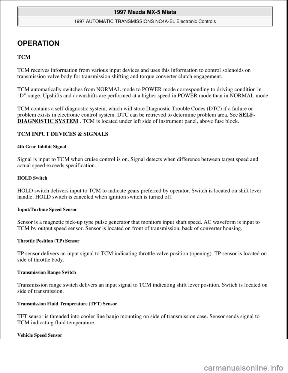
TCM
TCM receives information from various input devices and uses this information to control solenoids on
transmission valve body for transmission shifting and torque converter clutch engagement.
TCM automatically switches from NORMAL mode to POWER mode corresponding to driving condition in
"D" range. Upshifts and downshifts are performed at a higher speed in POWER mode than in NORMAL mode.
TCM contains a self-diagnostic system, which will store Diagnostic Trouble Codes (DTC) if a failure or
problem exists in electronic control system. DTC can be retrieved to determine problem area. See SELF-
DIAGNOSTIC SYSTEM . TCM is located under left side of instrument panel, above fuse block.
TCM INPUT DEVICES & SIGNALS
4th Gear Inhibit Signal
Signal is input to TCM when cruise control is on. Signal detects when difference between target speed and
actual speed exceeds specification.
HOLD Switch
HOLD switch delivers input to TCM to indicate gears preferred by operator. Switch is located on shift lever
handle. HOLD switch is canceled when ignition switch is turned off.
Input/Turbine Speed Sensor
Sensor is a magnetic pick-up type pulse generator that monitors input shaft speed. AC waveform is input to
TCM by output speed sensor. Sensor is located on front of transmission, back of converter housing.
Throttle Position (TP) Sensor
TP sensor delivers an input signal to TCM indicating throttle valve position (opening). TP sensor is located on
side of throttle body.
Transmission Range Switch
Transmission range switch delivers an input signal to TCM indicating shift lever position. Switch is located on
side of transmission.
Transmission Fluid Temperature (TFT) Sensor
TFT sensor is threaded into cooler line banjo mounting on side of transmission case. Sensor sends signal to
TCM indicating fluid temperature.
Vehicle Speed Sensor
1997 Mazda MX-5 Miata
1997 AUTOMATIC TRANSMISSIONS NC4A-EL Electronic Controls
Microsoft
Sunday, July 05, 2009 1:35:03 PMPage 2 © 2005 Mitchell Repair Information Company, LLC.
Page 55 of 514

CLEARING CODES
To clear DTC stored in TCM, use scan tool. See scan tool instruction manual. Road test vehicle.
COMPONENT LOCATION
COMPONENT LOCATION
COMPONENT CONNECTOR IDENTIFICATION
P0706 Transmission Range Sensor Range/Performance
P0710 (2) TFT Sensor Malfunction
P0711 (2) TFT Sensor Range/Performance
P0715 Input/Turbine Speed Sensor
P0725 Engine Speed Input Circuit Malfunction
P0731 Incorrect 1st Gear Ratio
P0732 Incorrect 2nd Gear Ratio
P0733 Incorrect 3rd Gear Ratio
P0734 Incorrect 4th Gear Ratio
P0740 TCC System Malfunction
P0750 1-2 Shift Solenoid
P0755 2-3 Shift Solenoid
P0760 3-4 Shift Solenoid
P1720 Vehicle Speed Sensor
P1743 Lock-Up Solenoid Valve
P1765 3-2 Timing Control Solenoid Valve
P1790 Throttle Position Sensor
P1795 Idle Switch
(1)Check listed component for probable cause. Check wiring and connection of specified component.
(2)Transmission Fluid Temperature.
DescriptionLocation
Engine Control ModuleBehind Passenger Seat
Input/Turbine Speed SensorMounted To 4th Gear Case
Shift SolenoidsSee Fig. 1
TCC Lock-Up SolenoidSee Fig. 1
Transmission Control UnitAbove Fuse Box
3-2 Control ValveSee Fig. 1
TFT SensorMounted In-Line To Cooler Line
Vehicle Speed SensorMounted In Speedometer
1997 Mazda MX-5 Miata
1997 AUTOMATIC TRANSMISSIONS NC4A-EL Electronic Controls
Microsoft
Sunday, July 05, 2009 1:35:03 PMPage 7 © 2005 Mitchell Repair Information Company, LLC.
Page 67 of 514

4. Inspect lock-up solenoid and related circuits. See SOLENOID VALVES under COMPONENT
TESTING. Repair as needed. If solenoid valve and related circuits are okay, go to next step.
5. Clear codes and road test vehicle. Retrieve DTC. If DTC P1743 is still present, replace TCM. If code is
no longer present, problem may be caused by poor connection. Repair as needed.
DTC P1765: 3-2 CONTROL SOLENOID VALVE MALFUNCTION
Possible Causes:
Short or open circuit between TCM and solenoid.
TCM malfunction.
3-2 control solenoid malfunction.
Diagnosis & Repair Procedure
1. Ensure all connections are clean and tight. Repair as needed. Turn ignition on. Access TCM connectors.
Using voltmeter, backprobe harness connectors. DO NOT disconnect connectors. Go to next step.
2. Drive vehicle and measure voltage between ground and terminal No. 2M (Blue/Orange wire). Battery
voltage should be present with solenoid on during 3-2 or 4-3 downshift, and zero volts with solenoid off.
If voltage is within specifications, go to step 5 . If voltage is not within specifications, go to next step.
3. Turn ignition off. Disconnect TCM harness connector. Measure resistance between ground and terminal
No. 2M. If resistance is 13-27 ohms at 68°F (20°C), go to step 5 . If resistance is not 13-27 ohms at 68°F
(20°C), go to next step.
4. Inspect 3-2 control clutch solenoid and related circuits. See SOLENOID VALVES
under
COMPONENT TESTING. Repair as needed. If solenoid valve and related circuits are okay, go to next
step.
5. Clear codes and road test vehicle. Retrieve DTC. If DTC P1765 is still present, replace TCM. If code is
no longer present, problem may be caused by poor connection. Repair as needed.
DTC P1790: THROTTLE POSITION (TP) SENSOR MALFUNCTION
Condition
TP sensor voltage is less than one volt or more than 4.9 volts. Possible causes are:
Poor harness connection at TP sensor.
Circuit fault between TP sensor and ECM or TCM.
TP sensor malfunction.
ECM or TCM malfunction.
Diagnosis & Repair Procedure
NOTE: If DTC P0725 is also present, repair it first and then proceed with this test.
1997 Mazda MX-5 Miata
1997 AUTOMATIC TRANSMISSIONS NC4A-EL Electronic Controls
Microsoft
Sunday, July 05, 2009 1:35:04 PMPage 19 © 2005 Mitchell Repair Information Company, LLC.
Page 68 of 514

1. Ensure all connections are clean and tight. Repair as needed. Ensure that TP sensor is adjusted correctly.
See appropriate ON-VEHICLE ADJUSTMENTS article in ENGINE PERFORMANCE. Turn ignition
on. Access TCM connectors. Using voltmeter, backprobe harness connectors. DO NOT disconnect
connectors. Go to next step.
2. Measure voltage between ground and terminal No. 2T (Red/Black wire) on TCM harness connector. With
throttle closed, voltage should be .1-1.1 volts. With wide open throttle, voltage should be 3.1-4.4 volts. If
voltage is within specification, go to step 5 . If voltage is not within specification, go to next step.
3. Measure voltage between ground and terminal No. 2A (Light Green/White wire) on TCM harness
connector. With ignition on, voltage should be 4.5-5.5 volts. With ignition off, voltage should be zero
volts. If voltage is within specification, go to step 5 . If voltage is not within specification, go to next step.
4. Inspect circuits between TP sensor and TCM. See appropriate wiring diagram under WIRING
DIAGRAMS . Repair as needed. If circuits are okay between sensor and TCM, go to next step.
5. Clear codes, and road test vehicle. Retrieve DTC. If DTC P1790 is still present, replace TCM. If code is
no longer present, system is okay.
DTC P1795: IDLE SWITCH OPEN OR SHORT
Condition
Closed throttle position switch is ON and TP sensor position is closed. Possible causes are:
Damaged wiring or connectors between closed throttle position switch and TCM.
Closed throttle position switch malfunction.
TCM malfunction.
Diagnosis & Repair Procedure
1. Ensure all connections are clean and tight. Repair as needed. Turn ignition on. Access TCM connectors.
Using voltmeter, backprobe harness connectors. DO NOT disconnect connectors. Go to next step.
2. Measure voltage between ground and terminal No. 1O (Red wire) on TCM harness connector. With
throttle closed, battery voltage should be present. With wide open throttle, voltage should be zero volts. If
voltage is within specification, go to step 5 . If voltage is not within specification, go to next step.
3. Inspect circuits between closed throttle position switch and TCM. See appropriate wiring diagram under
WIRING DIAGRAMS
. Repair as needed. If circuits are okay between sensor and TCM, go to next
step.
4. Disconnect battery negative cable. Disconnect closed throttle position switch connector. Check for
continuity between closed throttle position switch terminals. If continuity exists, go to next step. If
continuity does not exist, replace or adjust throttle position sensor.
5. Clear codes, and road test vehicle. Retrieve DTC. If DTC P1795 is still present, replace TCM. If code is
no longer present, problem is intermittent. Further investigation is required.
COMPONENT TESTING
NOTE: For connector terminal identification, see COMPONENT CONNECTOR
1997 Mazda MX-5 Miata
1997 AUTOMATIC TRANSMISSIONS NC4A-EL Electronic Controls
Microsoft
Sunday, July 05, 2009 1:35:04 PMPage 20 © 2005 Mitchell Repair Information Company, LLC.
Page 173 of 514
GENERAL INFORMATION
Computer Relearn Procedures
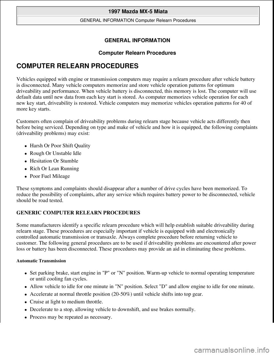
COMPUTER RELEARN PROCEDURES
Vehicles equipped with engine or transmission computers may require a relearn procedure after vehicle battery
is disconnected. Many vehicle computers memorize and store vehicle operation patterns for optimum
driveability and performance. When vehicle battery is disconnected, this memory is lost. The computer will use
default data until new data from each key start is stored. As computer memorizes vehicle operation for each
new key start, driveability is restored. Vehicle computers may memorize vehicles operation patterns for 40 of
more key starts.
Customers often complain of driveability problems during relearn stage because vehicle acts differently then
before being serviced. Depending on type and make of vehicle and how it is equipped, the following complaints
(driveability problems) may exist:
Harsh Or Poor Shift Quality
Rough Or Unstable Idle
Hesitation Or Stumble
Rich Or Lean Running
Poor Fuel Mileage
These symptoms and complaints should disappear after a number of drive cycles have been memorized. To
reduce the possibility of complaints, after any service which requires battery power to be disconnected, vehicle
should be road tested.
GENERIC COMPUTER RELEARN PROCEDURES
Some manufacturers identify a specific relearn procedure which will help establish suitable driveability during
relearn stage. These procedures are especially important if vehicle is equipped with and electronically
controlled automatic transmission or transaxle. Always complete procedure before returning vehicle to
customer. The following general procedures are to be used if driveability problems are encountered after power
loss or battery has been disconnected. These procedures may provide an aid in eliminating these problems.
Automatic Transmission
Set parking brake, start engine in "P" or "N" position. Warm-up vehicle to normal operating temperature
or until cooling fan cycles.
Allow vehicle to idle for one minute in "N" position. Select "D" and allow engine to idle for one minute.
Accelerate at normal throttle position (20-50%) until vehicle shifts into top gear.
Cruise at light to medium throttle.
Decelerate to a stop, allowing vehicle to downshift, and use brakes normally.
Process may be repeated as necessary.
1997 Mazda MX-5 Miata
GENERAL INFORMATION Computer Relearn Procedures
1997 Mazda MX-5 Miata
GENERAL INFORMATION Computer Relearn Procedures
Microsoft
Sunday, July 05, 2009 1:47:32 PMPage 1 © 2005 Mitchell Repair Information Company, LLC.
Microsoft
Sunday, July 05, 2009 1:47:35 PMPage 1 © 2005 Mitchell Repair Information Company, LLC.
Page 199 of 514
MOTORS
MOTORS
SENDING UNITS & SENSORS
SENDING UNITS & SENSORS
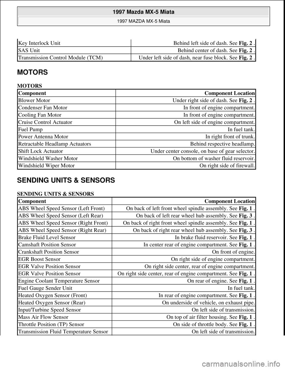
Key Interlock UnitBehind left side of dash. See Fig. 2 .
SAS UnitBehind center of dash. See Fig. 2 .
Transmission Control Module (TCM)Under left side of dash, near fuse block. See Fig. 2 .
ComponentComponent Location
Blower MotorUnder right side of dash. See Fig. 2 .
Condenser Fan MotorIn front of engine compartment.
Cooling Fan MotorIn front of engine compartment.
Cruise Control ActuatorOn left side of engine compartment.
Fuel PumpIn fuel tank.
Power Antenna MotorIn right front of trunk.
Retractable Headlamp ActuatorsBehind respective headlamp.
Shift Lock ActuatorUnder center console, on base of gear selector.
Windshield Washer MotorOn bottom of washer fluid reservoir.
Windshield Wiper MotorOn right side of firewall.
ComponentComponent Location
ABS Wheel Speed Sensor (Left Front)On back of left front wheel spindle assembly. See Fig. 1 .
ABS Wheel Speed Sensor (Left Rear)On back of left rear wheel hub assembly. See Fig. 3 .
ABS Wheel Speed Sensor (Right Front)On back of right front wheel spindle assembly. See Fig. 1 .
ABS Wheel Speed Sensor (Right Rear)On back of right rear wheel hub assembly. See Fig. 3 .
Brake Fluid Level SensorIn brake fluid reservoir. See Fig. 1 .
Camshaft Position SensorIn center rear of engine compartment. See Fig. 1 .
Crankshaft Position SensorOn front of engine.
EGR Boost SensorOn right side of engine compartment.
EGR Valve Position SensorOn right side center, rear of engine compartment.
EGR Valve Position SensorOn right side center, rear of engine compartment. See Fig. 1 .
Engine Coolant Temperature SensorOn rear of engine. See Fig. 1 .
Fuel Gauge Sender UnitIn fuel tank.
Heated Oxygen Sensor (Front)In rear of engine compartment. See Fig. 1 .
Heated Oxygen Sensor (Rear)On underside of vehicle, on exhaust pipe.
Input/Turbine Speed SensorOn left side of transmission.
Mass Air Flow SensorOn top of air filter housing. See Fig. 1 .
Throttle Position (TP) SensorOn side of throttle body. See Fig. 1 .
Transmission Fluid Temperature SensorOn left side of transmission.
1997 Mazda MX-5 Miata
1997 MAZDA MX-5 Miata
Microsoft
Sunday, July 05, 2009 1:54:00 PMPage 2 © 2005 Mitchell Repair Information Company, LLC.
Page 218 of 514
wheel puller. Pry out seal.
Installation
1. Apply light oil coat to seal lip. Using a hammer and seal installer, tap seal into oil pump body until it is
flush with edge of pump body. DO NOT bottom seal in pump body. Align keyway slots, and install
crankshaft sprocket and Woodruff key with tapered side toward oil pump body. Install crankshaft
sprocket bolt.
2. Using Crankshaft Lock Tool (49-D011-102), lock crankshaft sprocket into position. Tighten lock bolt to
specification. See TORQUE SPECIFICATIONS
.
3. Install timing belt. See TIMING BELT
under REMOVAL & INSTALLATION. Install timing belt
covers, pulleys and drive belts. Reconnect negative battery cable and ensure timing is correct.
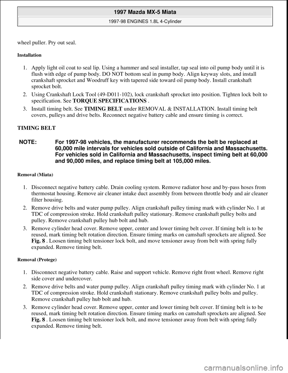
TIMING BELT
Removal (Miata)
1. Disconnect negative battery cable. Drain cooling system. Remove radiator hose and by-pass hoses from
thermostat housing. Remove air cleaner intake duct assembly from between throttle body and air cleaner
filter housing.
2. Remove drive belts and water pump pulley. Align crankshaft pulley timing mark with cylinder No. 1 at
TDC of compression stroke. Hold crankshaft pulley stationary. Remove crankshaft pulley bolts and
pulley. Remove crankshaft pulley hub bolt and hub.
3. Remove cylinder head cover. Remove upper, center and lower timing belt cover. If timing belt is to be
reused, mark timing belt rotation direction. Ensure timing marks on camshaft sprockets are aligned. See
Fig. 8
. Loosen timing belt tensioner lock bolt, and move tensioner away from belt with spring fully
expanded. Remove timing belt.
Removal (Protege)
1. Disconnect negative battery cable. Raise and support vehicle. Remove right front wheel. Remove right
side cover and undercover.
2. Remove drive belts and water pump pulley. Align crankshaft pulley timing mark with cylinder No. 1 at
TDC of compression stroke. Hold crankshaft stationary. Remove crankshaft pulley bolts and pulley.
Remove crankshaft pulley hub bolt and hub.
3. Remove cylinder head cover. Remove upper, center and lower timing belt cover. If timing belt is to be
reused, mark timing belt rotation direction. Ensure timing marks on camshaft sprockets are aligned. See
Fig. 8
. Loosen timing belt tensioner lock bolt, and move tensioner away from belt with spring fully
expanded. Remove timin
g belt. NOTE: For 1997-98 vehicles, the manufacturer recommends the belt be replaced at
60,000 mile intervals for vehicles sold outside of California and Massachusetts.
For vehicles sold in California and Massachusetts, inspect timing belt at 60,000
and 90,000 miles, and replace timing belt at 105,000 miles.
1997 Mazda MX-5 Miata
1997-98 ENGINES 1.8L 4-Cylinder
Microsoft
Sunday, July 05, 2009 1:55:15 PMPage 12 © 2005 Mitchell Repair Information Company, LLC.
Page 227 of 514
1. Drain engine coolant. Disconnect battery cable. Position No. 1 cylinder at TDC of compression stroke.
On Protege, remove right side cover and undercover.
2. On Miata, remove air cleaner intake duct from between throttle body and air cleaner/filter assembly. On
all models, remove upper radiator hose and by-pass hoses from thermostat housing.
3. Remove drive belts and water pump pulley. Remove power steering pump with hoses attached and secure
pump away from engine (if necessary). Remove timing belt, tensioner and idler. See TIMING BELT.
4. Unbolt water inlet pipe from water pump. Water pump inlet pipe has lower radiator hose and by-pass pipe
attached to it. Remove bolts from water pump. To install, reverse removal procedure. Tighten bolt to
specification. See TORQUE SPECIFICATIONS
.
OIL PAN
Removal & Installation (Miata)
1. Disconnect negative battery cable. Drain engine oil. Remove dipstick, tube and "O" ring. Raise vehicle on
hoist. Remove engine undercover. Disconnect steering column shaft at steering rack coupling. See Fig.
14 . Remove engine mount nuts. Lift and support engine using jack.
2. Support crossmember using transmission jack and remove crossmember bolts. Slowly and carefully lower
crossmember until clearance between oil pan and steering rack is about 4 inches. Remove oil pan bolts
from engine block and transmission.
3. DO NOT damage sealant contact surfaces. Remove oil pan by prying between oil pan and transmission
support. Remove oil pan baffle by prying it from engine. See Fig. 14
. DO NOT deform oil pan baffle.
Replace oil pan baffle if deformed. Clean sealant from oil pan, bolts, engine block and both sides of oil
pan baffle.
4. To install, apply oil resistant sealant to engine block and oil pan. Install oil pan baffle and oil pan within 5
minutes of applying sealant. To complete installation, reverse removal procedure. Tighten bolts to
specification. See TORQUE SPECIFICATIONS
. Fill engine with oil to specification. See ENGINE
LUBRICATION SYSTEM under ENGINE OILING. NOTE: For further information on cooling systems, see SPECIFICATIONS & ELECTRIC
COOLING FANS article in ENGINE COOLING.
NOTE: On Miata, engine must be supported in order to remove oil pan.
1997 Mazda MX-5 Miata
1997-98 ENGINES 1.8L 4-Cylinder
Microsoft
Sunday, July 05, 2009 1:55:15 PMPage 21 © 2005 Mitchell Repair Information Company, LLC.