1997 MAZDA MIATA cooling fan
[x] Cancel search: cooling fanPage 173 of 514
GENERAL INFORMATION
Computer Relearn Procedures
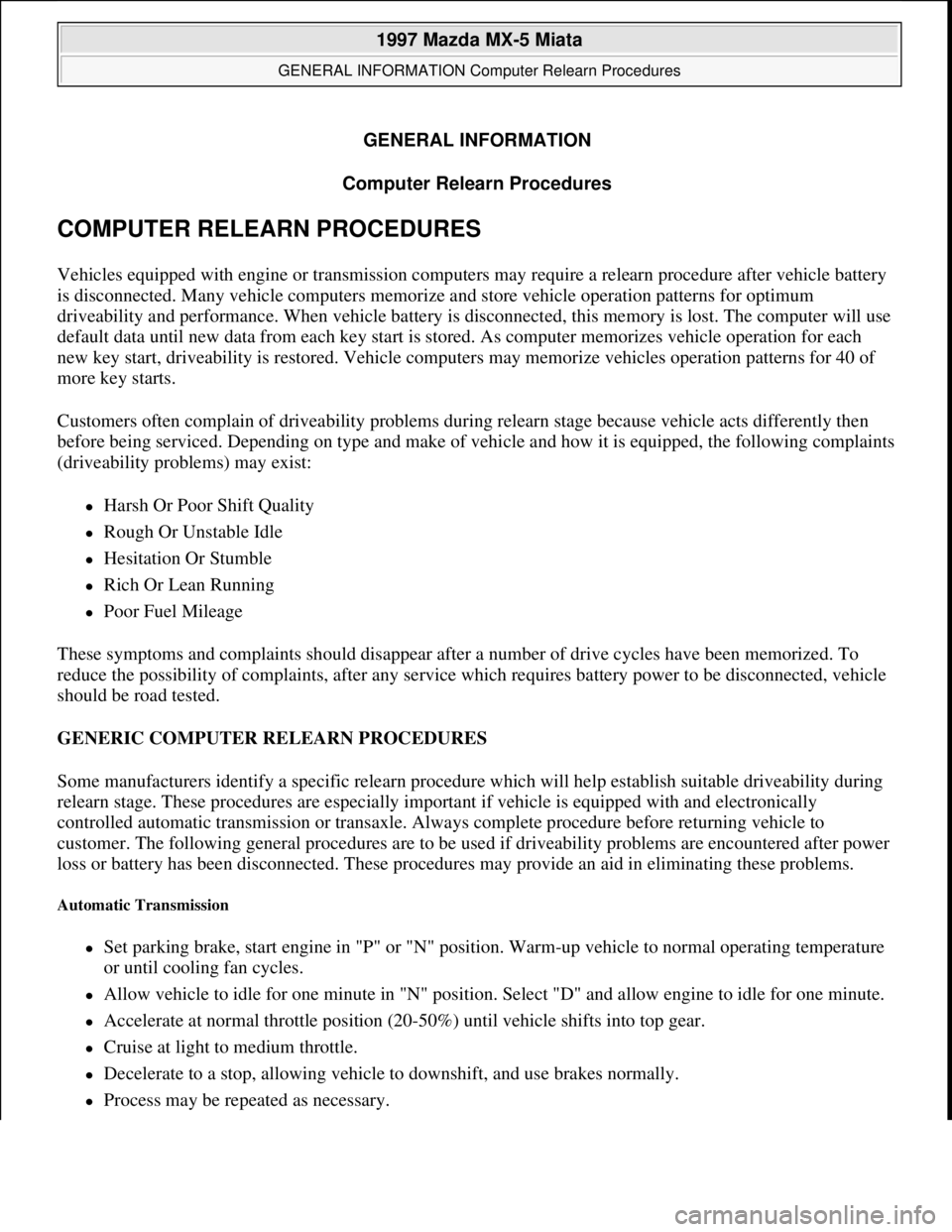
COMPUTER RELEARN PROCEDURES
Vehicles equipped with engine or transmission computers may require a relearn procedure after vehicle battery
is disconnected. Many vehicle computers memorize and store vehicle operation patterns for optimum
driveability and performance. When vehicle battery is disconnected, this memory is lost. The computer will use
default data until new data from each key start is stored. As computer memorizes vehicle operation for each
new key start, driveability is restored. Vehicle computers may memorize vehicles operation patterns for 40 of
more key starts.
Customers often complain of driveability problems during relearn stage because vehicle acts differently then
before being serviced. Depending on type and make of vehicle and how it is equipped, the following complaints
(driveability problems) may exist:
Harsh Or Poor Shift Quality
Rough Or Unstable Idle
Hesitation Or Stumble
Rich Or Lean Running
Poor Fuel Mileage
These symptoms and complaints should disappear after a number of drive cycles have been memorized. To
reduce the possibility of complaints, after any service which requires battery power to be disconnected, vehicle
should be road tested.
GENERIC COMPUTER RELEARN PROCEDURES
Some manufacturers identify a specific relearn procedure which will help establish suitable driveability during
relearn stage. These procedures are especially important if vehicle is equipped with and electronically
controlled automatic transmission or transaxle. Always complete procedure before returning vehicle to
customer. The following general procedures are to be used if driveability problems are encountered after power
loss or battery has been disconnected. These procedures may provide an aid in eliminating these problems.
Automatic Transmission
Set parking brake, start engine in "P" or "N" position. Warm-up vehicle to normal operating temperature
or until cooling fan cycles.
Allow vehicle to idle for one minute in "N" position. Select "D" and allow engine to idle for one minute.
Accelerate at normal throttle position (20-50%) until vehicle shifts into top gear.
Cruise at light to medium throttle.
Decelerate to a stop, allowing vehicle to downshift, and use brakes normally.
Process may be repeated as necessary.
1997 Mazda MX-5 Miata
GENERAL INFORMATION Computer Relearn Procedures
1997 Mazda MX-5 Miata
GENERAL INFORMATION Computer Relearn Procedures
Microsoft
Sunday, July 05, 2009 1:47:32 PMPage 1 © 2005 Mitchell Repair Information Company, LLC.
Microsoft
Sunday, July 05, 2009 1:47:35 PMPage 1 © 2005 Mitchell Repair Information Company, LLC.
Page 198 of 514

1997 MAZDA
MX-5 Miata
BUZZERS, RELAYS & TIMERS
BUZZERS, RELAYS & TIMERS
CIRCUIT PROTECTION DEVICES
CIRCUIT PROTECTION DEVICES
CONTROL UNITS
CONTROL UNITS
ComponentComponent Location
A/C RelayIn right front of engine compartment, near radiator. See Fig. 1 .
Condenser Fan RelayIn right front of engine compartment, near radiator. See Fig. 1 .
Cooling Fan RelayIn main fuse/relay block.
Flasher UnitBehind left side of dash. See Fig. 2 .
Fuel Pump RelayUnder left side of dash. See Fig. 2 .
Headlamp RelayOn left rear corner of front inner fender panel. See Fig. 1 .
Horn RelayOn left rear corner of front inner fender panel. See Fig. 1 .
INT RelayIntegral with windshield wiper & washer switch.
Main RelayIn left rear corner of engine compartment, in main fuse/relay block.
Power Antenna RelayIn right rear of vehicle, attached to power antenna.
Rear Window Defogger
RelayIn center rear of trunk compartment. See Fig. 3 .
Retractable Headlamp RelayBehind left side of dash.
TNS RelayIn left rear corner of engine compartment, on inner fender panel. See Fig.
1 .
Warning UnitBehind left side of dash. See Fig. 2 .
ComponentComponent Location
Fuse Block (Front)Behind left side of dash. See Fig. 2 .
Fuse Block (Rear)On right rear side of luggage compartment. See Fig. 3 .
Main Fuse BlockOn right rear corner of engine compartment, near firewall. See Fig. 1 .
ComponentComponent Location
ABS Control ModuleBehind passenger's seat. See Fig. 3 .
ABS Control UnitIn right rear corner of engine compartment.
Cruise Control ModuleUnder left side of dash above fuse block. See Fig. 2 .
Daytime Running Lamp (DRL) Control ModuleOn bracket, behind left side of dash. See Fig. 2 .
Engine Control Module (ECM)Behind passenger's seat. See Fig. 3 .
1997 Mazda MX-5 Miata
1997 MAZDA MX-5 Miata
1997 Mazda MX-5 Miata
1997 MAZDA MX-5 Miata
Microsoft
Sunday, July 05, 2009 1:54:00 PMPage 1 © 2005 Mitchell Repair Information Company, LLC.
Microsoft
Sunday, July 05, 2009 1:54:09 PMPage 1 © 2005 Mitchell Repair Information Company, LLC.
Page 199 of 514
MOTORS
MOTORS
SENDING UNITS & SENSORS
SENDING UNITS & SENSORS
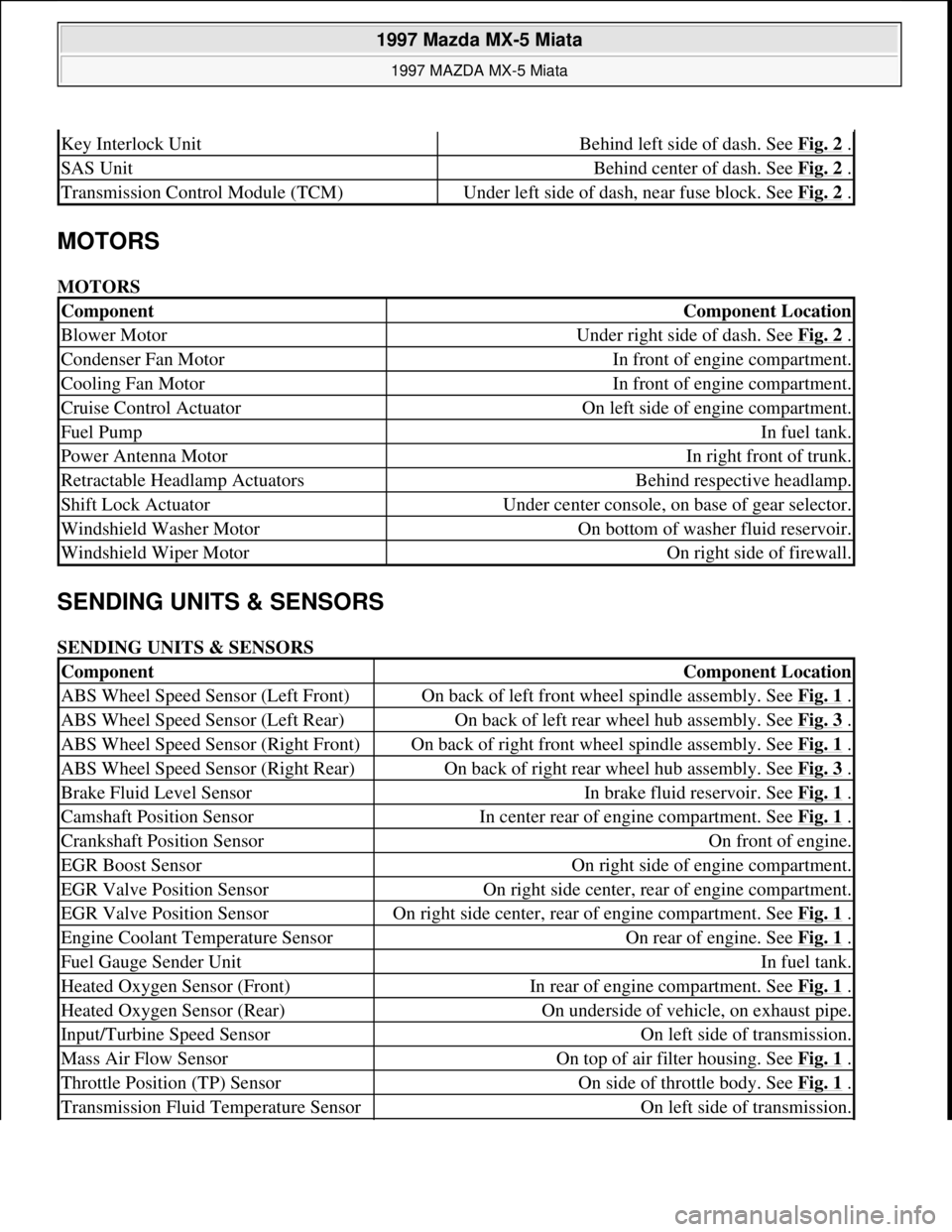
Key Interlock UnitBehind left side of dash. See Fig. 2 .
SAS UnitBehind center of dash. See Fig. 2 .
Transmission Control Module (TCM)Under left side of dash, near fuse block. See Fig. 2 .
ComponentComponent Location
Blower MotorUnder right side of dash. See Fig. 2 .
Condenser Fan MotorIn front of engine compartment.
Cooling Fan MotorIn front of engine compartment.
Cruise Control ActuatorOn left side of engine compartment.
Fuel PumpIn fuel tank.
Power Antenna MotorIn right front of trunk.
Retractable Headlamp ActuatorsBehind respective headlamp.
Shift Lock ActuatorUnder center console, on base of gear selector.
Windshield Washer MotorOn bottom of washer fluid reservoir.
Windshield Wiper MotorOn right side of firewall.
ComponentComponent Location
ABS Wheel Speed Sensor (Left Front)On back of left front wheel spindle assembly. See Fig. 1 .
ABS Wheel Speed Sensor (Left Rear)On back of left rear wheel hub assembly. See Fig. 3 .
ABS Wheel Speed Sensor (Right Front)On back of right front wheel spindle assembly. See Fig. 1 .
ABS Wheel Speed Sensor (Right Rear)On back of right rear wheel hub assembly. See Fig. 3 .
Brake Fluid Level SensorIn brake fluid reservoir. See Fig. 1 .
Camshaft Position SensorIn center rear of engine compartment. See Fig. 1 .
Crankshaft Position SensorOn front of engine.
EGR Boost SensorOn right side of engine compartment.
EGR Valve Position SensorOn right side center, rear of engine compartment.
EGR Valve Position SensorOn right side center, rear of engine compartment. See Fig. 1 .
Engine Coolant Temperature SensorOn rear of engine. See Fig. 1 .
Fuel Gauge Sender UnitIn fuel tank.
Heated Oxygen Sensor (Front)In rear of engine compartment. See Fig. 1 .
Heated Oxygen Sensor (Rear)On underside of vehicle, on exhaust pipe.
Input/Turbine Speed SensorOn left side of transmission.
Mass Air Flow SensorOn top of air filter housing. See Fig. 1 .
Throttle Position (TP) SensorOn side of throttle body. See Fig. 1 .
Transmission Fluid Temperature SensorOn left side of transmission.
1997 Mazda MX-5 Miata
1997 MAZDA MX-5 Miata
Microsoft
Sunday, July 05, 2009 1:54:00 PMPage 2 © 2005 Mitchell Repair Information Company, LLC.
Page 210 of 514
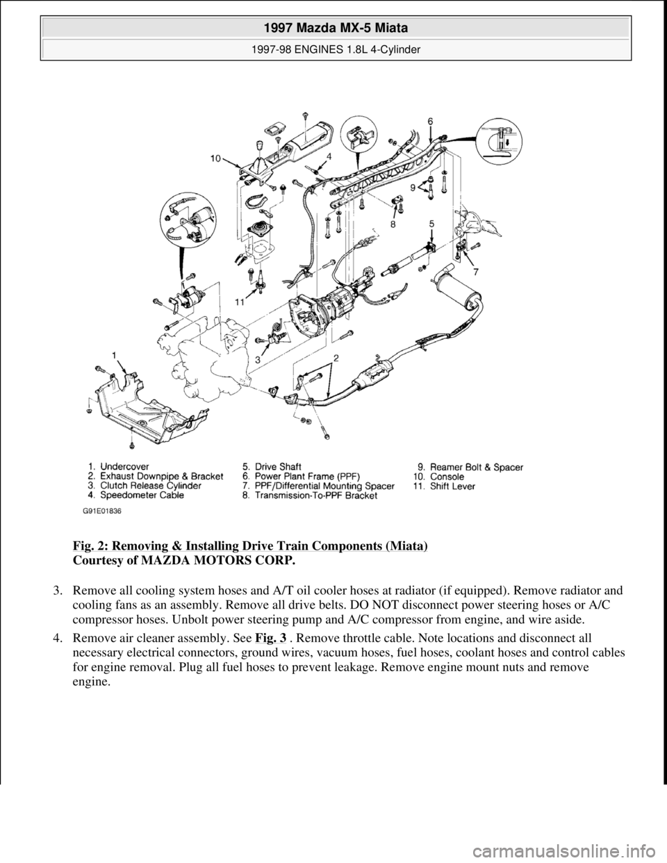
Fig. 2: Removing & Installing Drive Train Components (Miata)
Courtesy of MAZDA MOTORS CORP.
3. Remove all cooling system hoses and A/T oil cooler hoses at radiator (if equipped). Remove radiator and
cooling fans as an assembly. Remove all drive belts. DO NOT disconnect power steering hoses or A/C
compressor hoses. Unbolt power steering pump and A/C compressor from engine, and wire aside.
4. Remove air cleaner assembly. See Fig. 3
. Remove throttle cable. Note locations and disconnect all
necessary electrical connectors, ground wires, vacuum hoses, fuel hoses, coolant hoses and control cables
for engine removal. Plug all fuel hoses to prevent leakage. Remove engine mount nuts and remove
en
gine.
1997 Mazda MX-5 Miata
1997-98 ENGINES 1.8L 4-Cylinder
Microsoft
Sunday, July 05, 2009 1:55:15 PMPage 4 © 2005 Mitchell Repair Information Company, LLC.
Page 227 of 514
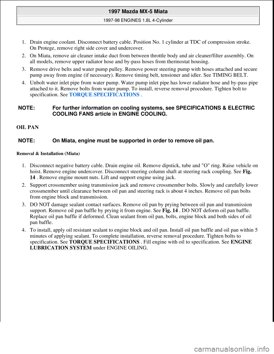
1. Drain engine coolant. Disconnect battery cable. Position No. 1 cylinder at TDC of compression stroke.
On Protege, remove right side cover and undercover.
2. On Miata, remove air cleaner intake duct from between throttle body and air cleaner/filter assembly. On
all models, remove upper radiator hose and by-pass hoses from thermostat housing.
3. Remove drive belts and water pump pulley. Remove power steering pump with hoses attached and secure
pump away from engine (if necessary). Remove timing belt, tensioner and idler. See TIMING BELT.
4. Unbolt water inlet pipe from water pump. Water pump inlet pipe has lower radiator hose and by-pass pipe
attached to it. Remove bolts from water pump. To install, reverse removal procedure. Tighten bolt to
specification. See TORQUE SPECIFICATIONS
.
OIL PAN
Removal & Installation (Miata)
1. Disconnect negative battery cable. Drain engine oil. Remove dipstick, tube and "O" ring. Raise vehicle on
hoist. Remove engine undercover. Disconnect steering column shaft at steering rack coupling. See Fig.
14 . Remove engine mount nuts. Lift and support engine using jack.
2. Support crossmember using transmission jack and remove crossmember bolts. Slowly and carefully lower
crossmember until clearance between oil pan and steering rack is about 4 inches. Remove oil pan bolts
from engine block and transmission.
3. DO NOT damage sealant contact surfaces. Remove oil pan by prying between oil pan and transmission
support. Remove oil pan baffle by prying it from engine. See Fig. 14
. DO NOT deform oil pan baffle.
Replace oil pan baffle if deformed. Clean sealant from oil pan, bolts, engine block and both sides of oil
pan baffle.
4. To install, apply oil resistant sealant to engine block and oil pan. Install oil pan baffle and oil pan within 5
minutes of applying sealant. To complete installation, reverse removal procedure. Tighten bolts to
specification. See TORQUE SPECIFICATIONS
. Fill engine with oil to specification. See ENGINE
LUBRICATION SYSTEM under ENGINE OILING. NOTE: For further information on cooling systems, see SPECIFICATIONS & ELECTRIC
COOLING FANS article in ENGINE COOLING.
NOTE: On Miata, engine must be supported in order to remove oil pan.
1997 Mazda MX-5 Miata
1997-98 ENGINES 1.8L 4-Cylinder
Microsoft
Sunday, July 05, 2009 1:55:15 PMPage 21 © 2005 Mitchell Repair Information Company, LLC.
Page 311 of 514

ELECTRICAL COMPONENT LOCATIONS
OPERATION
All air control doors are controlled manually by cable from control panel. Blower resistor determines blower
speed. With blower switch in high position, blower motor is grounded directly through blower switch. With
blower switch in all other positions, blower motor is grounded through blower resistor and blower switch.
A/C compressor clutch circuit is completed when A/C relay is energized and pressure switch is closed. A/C
relay is energized when Powertrain Control Module (PCM) grounds the solenoid circuit of the relay. The PCM
energizes A/C relay if evaporator thermoswitch is closed and A/C and blower switches are on. The PCM also
controls A/C relay operation according to engine load.
ADJUSTMENTS
TESTING
A/C SYSTEM PERFORMANCE
1. Connect manifold gauge set. Operate engine at 1500 RPM. Operate A/C at maximum cooling, recirculate,
fan on high, vent mode. Close all doors and windows. Place thermometer at center vent outlet.
2. Allow A/C to stabilize. Ensure high pressure is 200-227 psi (14.0-16.0 kg/cm
2 ). Read temperature at
center vent outlet. Ensure temperature is within 39-43°F (3-6°C)
A/C COMPRESSOR CLUTCH CIRCUIT
ComponentLocation
A/C RelayRight Front Corner Of Engine Compartment
Condenser FanRight Front Corner Of Engine Compartment
Blower ResistorBottom Of Blower Case
Evaporator ThermoswitchOn Evaporator Upper Case
Pressure SwitchIn High-Pressure Line, Between Receiver-Drier &
Evaporator
NOTE: For door control cable adjustments, see ADJUSTMENTS in HEATER SYSTEM
article.
WARNING:To avoid injury from accidental air bag deployment, read and follow all
SERVICE PRECAUTIONS and DISABLING & ACTIVATING AIR BAG
SYSTEM procedures in AIR BAG RESTRAINT SYSTEM article in the
ACCESSORIES/SAFETY EQUIPMENT section.
NOTE: For test procedures not covered in this article, see TESTING in HEATER
SYSTEM article.
1997 Mazda MX-5 Miata
A/C-HEATER SYSTEM - MANUAL 1997 Manual A/C-Heater System
Microsoft
Sunday, July 05, 2009 1:41:48 PMPage 2 © 2005 Mitchell Repair Information Company, LLC.
Page 327 of 514
HALOGEN BULBS
HEADLIGHT RETRACTOR
RADIATOR CAP
RADIATOR FAN
WARRANTY INFORMATION
BASIC NEW CAR WARRANTY
Basic components are warranted against defects in materials and workmanship for 36 months or 50,000 miles,
whichever occurs first. Tires are covered by a separate warranty offered by tire manufacturer.
ANTI-PERFORATION WARRANTY
Covers body sheet metal panels for 60 months, regardless of mileage, against perforation due to corrosion.
SAFETY RESTRAINT SYSTEM WARRANTY WARNING:Relieve fuel system pressure prior to servicing any fuel system
component (fuel injection models).
WARNING:Halogen bulbs contain pressurized gas which may explode if overheated.
DO NOT touch glass portion of bulb with bare hands. Eye protection
should be worn when handling or working around halogen bulbs.
CAUTION: If headlight retractor freezes during cold weather operation, DO NOT
attempt to force mechanism. Headlights should be kept raised at all times
in cold weather. To raise them, use only headlight retractor switch. DO
NOT use headlight switch.
CAUTION: Always disconnect the fan motor when working near the radiator fan. The
fan is temperature controlled and could start at any time even when the
ignition key is in the OFF position. DO NOT loosen or remove radiator cap
when cooling system is hot.
WARNING:Keep hands away from radiator fan. Fan is controlled by a thermostatic
switch which may come on or run for up to 15 minutes even after engine
is turned off.
CAUTION: Always refer to customer's copy of warranty information for specific
model application and/or coverage limitations.
1997 Mazda MX-5 Miata
MAINTENANCE INFORMATION 1997 MAINTENANCE Mazda Maintenance Information
Microsoft
Sunday, July 05, 2009 1:41:19 PMPage 7 © 2005 Mitchell Repair Information Company, LLC.
Page 329 of 514
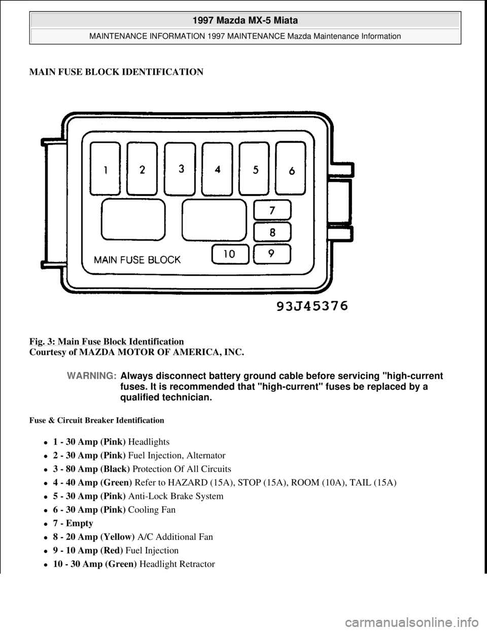
MAIN FUSE BLOCK IDENTIFICATION
Fig. 3: Main Fuse Block Identification
Courtesy of MAZDA MOTOR OF AMERICA, INC.
Fuse & Circuit Breaker Identification
1 - 30 Amp (Pink) Headlights
2 - 30 Amp (Pink) Fuel Injection, Alternator
3 - 80 Amp (Black) Protection Of All Circuits
4 - 40 Amp (Green) Refer to HAZARD (15A), STOP (15A), ROOM (10A), TAIL (15A)
5 - 30 Amp (Pink) Anti-Lock Brake System
6 - 30 Amp (Pink) Cooling Fan
7 - Empty
8 - 20 Amp (Yellow) A/C Additional Fan
9 - 10 Amp (Red) Fuel Injection
10 - 30 Amp (Green) Headlight Retractor
WARNING:Always disconnect battery ground cable before servicing "high-current
fuses. It is recommended that "high-current" fuses be replaced by a
qualified technician.
1997 Mazda MX-5 Miata
MAINTENANCE INFORMATION 1997 MAINTENANCE Mazda Maintenance Information
Microsoft
Sunday, July 05, 2009 1:41:19 PMPage 9 © 2005 Mitchell Repair Information Company, LLC.