1997 MAZDA MIATA center console
[x] Cancel search: center consolePage 49 of 514

1997 AUTOMATIC TRANSMISSIONS
NC4A-EL Electronic Controls
APPLICATION
TRANSMISSION APPLICATION
DESCRIPTION
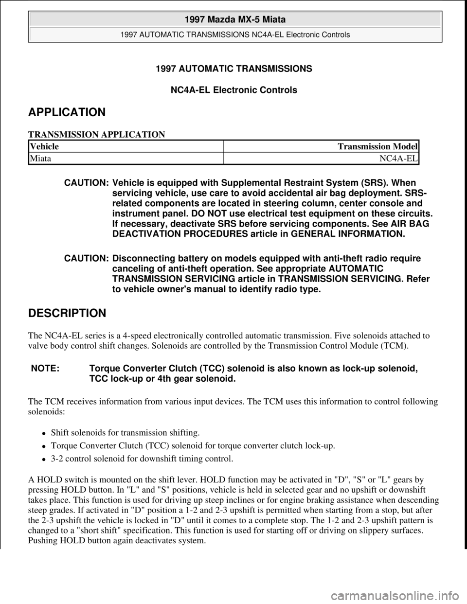
The NC4A-EL series is a 4-speed electronically controlled automatic transmission. Five solenoids attached to
valve body control shift changes. Solenoids are controlled by the Transmission Control Module (TCM).
The TCM receives information from various input devices. The TCM uses this information to control following
solenoids:
Shift solenoids for transmission shifting.
Torque Converter Clutch (TCC) solenoid for torque converter clutch lock-up.
3-2 control solenoid for downshift timing control.
A HOLD switch is mounted on the shift lever. HOLD function may be activated in "D", "S" or "L" gears by
pressing HOLD button. In "L" and "S" positions, vehicle is held in selected gear and no upshift or downshift
takes place. This function is used for driving up steep inclines or for engine braking assistance when descending
steep grades. If activated in "D" position a 1-2 and 2-3 upshift is permitted when starting from a stop, but after
the 2-3 upshift the vehicle is locked in "D" until it comes to a complete stop. The 1-2 and 2-3 upshift pattern is
changed to a "short shift" specification. This function is used for starting off or driving on slippery surfaces.
Pushin
g HOLD button again deactivates system.
VehicleTransmission Model
MiataNC4A-EL
CAUTION: Vehicle is equipped with Supplemental Restraint System (SRS). When
servicing vehicle, use care to avoid accidental air bag deployment. SRS-
related components are located in steering column, center console and
instrument panel. DO NOT use electrical test equipment on these circuits.
If necessary, deactivate SRS before servicing components. See AIR BAG
DEACTIVATION PROCEDURES article in GENERAL INFORMATION.
CAUTION: Disconnecting battery on models equipped with anti-theft radio require
canceling of anti-theft operation. See appropriate AUTOMATIC
TRANSMISSION SERVICING article in TRANSMISSION SERVICING. Refer
to vehicle owner's manual to identify radio type.
NOTE: Torque Converter Clutch (TCC) solenoid is also known as lock-up solenoid,
TCC lock-up or 4th gear solenoid.
1997 Mazda MX-5 Miata
1997 AUTOMATIC TRANSMISSIONS NC4A-EL Electronic Controls
1997 Mazda MX-5 Miata
1997 AUTOMATIC TRANSMISSIONS NC4A-EL Electronic Controls
Microsoft
Sunday, July 05, 2009 1:35:03 PMPage 1 © 2005 Mitchell Repair Information Company, LLC.
Microsoft
Sunday, July 05, 2009 1:35:38 PMPage 1 © 2005 Mitchell Repair Information Company, LLC.
Page 53 of 514

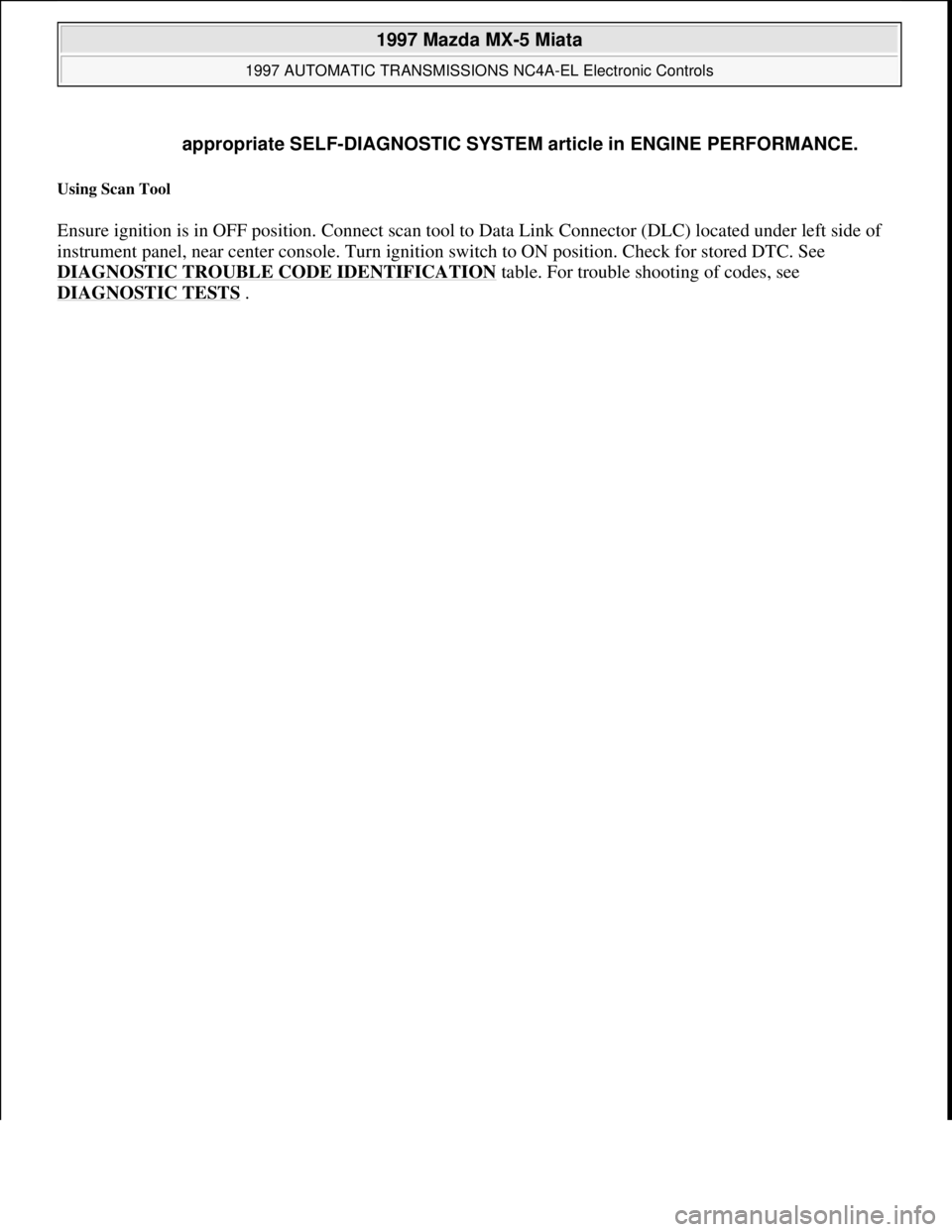
Using Scan Tool
Ensure ignition is in OFF position. Connect scan tool to Data Link Connector (DLC) located under left side of
instrument panel, near center console. Turn ignition switch to ON position. Check for stored DTC. See
DIAGNOSTIC TROUBLE CODE IDENTIFICATION
table. For trouble shooting of codes, see
DIAGNOSTIC TESTS
. appropriate SELF-DIAGNOSTIC SYSTEM article in ENGINE PERFORMANCE.
1997 Mazda MX-5 Miata
1997 AUTOMATIC TRANSMISSIONS NC4A-EL Electronic Controls
Microsoft
Sunday, July 05, 2009 1:35:03 PMPage 5 © 2005 Mitchell Repair Information Company, LLC.
Page 69 of 514

HOLD SWITCH
1. Turn ignition on. Ensure HOLD indicator illuminates with switch depressed. Ensure indicator light is not
illuminated when switch is released. If switch is not working as described, go to next step.
2. Access switch connector under center console. Disconnect connector. Check continuity between
terminals "A" and "B". See Fig. 6
. Continuity should exist when switch is depressed. When switch is
released, continuity should not exist. Replace as needed. If HOLD switch system does not function
correctly, inspect circuits between switch and TCM. See appropriate wiring diagram in WIRING
DIAGRAMS .
Fig. 6: Testing HOLD Switch
Courtesy of MAZDA MOTORS CORP.
INPUT/TURBINE SPEED SENSOR IDENTIFICATION
table under SELF-DIAGNOSTIC SYSTEM. For circuit or wire
color identification, see appropriate wiring diagram in WIRING DIAGRAMS
.
1997 Mazda MX-5 Miata
1997 AUTOMATIC TRANSMISSIONS NC4A-EL Electronic Controls
Microsoft
Sunday, July 05, 2009 1:35:04 PMPage 21 © 2005 Mitchell Repair Information Company, LLC.
Page 199 of 514

MOTORS
MOTORS
SENDING UNITS & SENSORS
SENDING UNITS & SENSORS
Key Interlock UnitBehind left side of dash. See Fig. 2 .
SAS UnitBehind center of dash. See Fig. 2 .
Transmission Control Module (TCM)Under left side of dash, near fuse block. See Fig. 2 .
ComponentComponent Location
Blower MotorUnder right side of dash. See Fig. 2 .
Condenser Fan MotorIn front of engine compartment.
Cooling Fan MotorIn front of engine compartment.
Cruise Control ActuatorOn left side of engine compartment.
Fuel PumpIn fuel tank.
Power Antenna MotorIn right front of trunk.
Retractable Headlamp ActuatorsBehind respective headlamp.
Shift Lock ActuatorUnder center console, on base of gear selector.
Windshield Washer MotorOn bottom of washer fluid reservoir.
Windshield Wiper MotorOn right side of firewall.
ComponentComponent Location
ABS Wheel Speed Sensor (Left Front)On back of left front wheel spindle assembly. See Fig. 1 .
ABS Wheel Speed Sensor (Left Rear)On back of left rear wheel hub assembly. See Fig. 3 .
ABS Wheel Speed Sensor (Right Front)On back of right front wheel spindle assembly. See Fig. 1 .
ABS Wheel Speed Sensor (Right Rear)On back of right rear wheel hub assembly. See Fig. 3 .
Brake Fluid Level SensorIn brake fluid reservoir. See Fig. 1 .
Camshaft Position SensorIn center rear of engine compartment. See Fig. 1 .
Crankshaft Position SensorOn front of engine.
EGR Boost SensorOn right side of engine compartment.
EGR Valve Position SensorOn right side center, rear of engine compartment.
EGR Valve Position SensorOn right side center, rear of engine compartment. See Fig. 1 .
Engine Coolant Temperature SensorOn rear of engine. See Fig. 1 .
Fuel Gauge Sender UnitIn fuel tank.
Heated Oxygen Sensor (Front)In rear of engine compartment. See Fig. 1 .
Heated Oxygen Sensor (Rear)On underside of vehicle, on exhaust pipe.
Input/Turbine Speed SensorOn left side of transmission.
Mass Air Flow SensorOn top of air filter housing. See Fig. 1 .
Throttle Position (TP) SensorOn side of throttle body. See Fig. 1 .
Transmission Fluid Temperature SensorOn left side of transmission.
1997 Mazda MX-5 Miata
1997 MAZDA MX-5 Miata
Microsoft
Sunday, July 05, 2009 1:54:00 PMPage 2 © 2005 Mitchell Repair Information Company, LLC.
Page 200 of 514

SOLENOIDS & SOLENOID VALVES
SOLENOIDS & SOLENOID VALVES
SWITCHES
SWITCHES
MISCELLANEOUS
MISCELLANEOUS
Vehicle Speed Sensor (VSS)On speedometer assembly.
Water Temperature Sender UnitOn center of engine. See Fig. 1 .
Washer Fluid Level SensorOn washer fluid reservoir. See Fig. 1 .
ComponentComponent Location
AT Interlock SolenoidIn steering column, near ignition switch. See Fig. 2 .
EC-AT Solenoid ValveOn left side of transmission.
EGR Solenoid Valve (Vacuum)On right side of engine compartment. See Fig. 1 .
EGR Solenoid Valve (Vent)On right side of engine compartment. See Fig. 1 .
Fourth Gear Solenoid ValveOn left side of transmission.
Idle Air Control ValveOn right side, front of engine compartment. See Fig. 1 .
PRC Solenoid ValveOn right side, front of engine. See Fig. 1 .
Purge Solenoid ValveOn right strut tower. See Fig. 1 .
ComponentComponent Location
Back-Up Lamp Switch (M/T)On right side of transmission. See Fig. 1 .
Brake SwitchOn bracket, above brake pedal. See Fig. 2 .
Buckle SwitchOn driver side seat belt buckle. See Fig. 3 .
Clutch Switch (M/T)On bracket, above clutch pedal. See Fig. 2 .
Hold SwitchUnder right side of center console.
Key Reminder SwitchIn steering column, near ignition switch.
Neutral Switch (M/T)On right side of transmission. See Fig. 1 .
Oil Pressure SwitchOn right side of engine. See Fig. 1 .
"P" Range SwitchUnder center console, on base of gear selector.
Parking Brake SwitchOn base of parking brake lever. See Fig. 4 .
Power Steering Pressure SwitchOn power steering pump assembly.
Refrigerant Pressure SwitchIn front of engine compartment, near radiator support. See Fig. 1 .
Starter Interlock Switch (M/T)On bracket, above clutch pedal. See Fig. 2 .
ThermoswitchUnder right side of dash.
Transmission Range SwitchOn left side of transmission.
ComponentComponent Location
1997 Mazda MX-5 Miata
1997 MAZDA MX-5 Miata
Microsoft
Sunday, July 05, 2009 1:54:00 PMPage 3 © 2005 Mitchell Repair Information Company, LLC.
Page 201 of 514

CONNECTORS
CONNECTORS
GROUNDS
GROUNDS
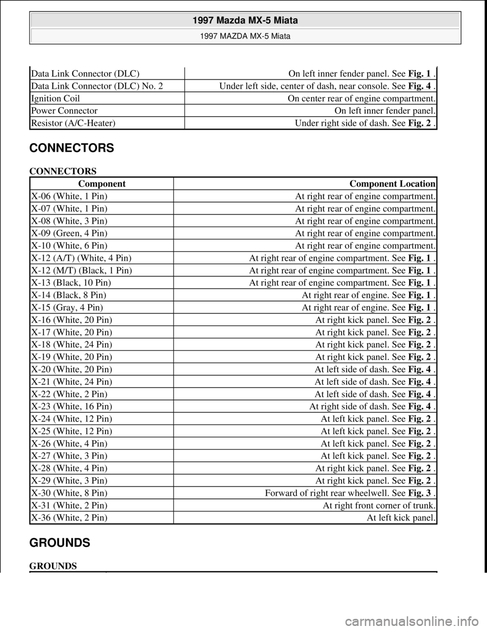
Data Link Connector (DLC)On left inner fender panel. See Fig. 1 .
Data Link Connector (DLC) No. 2Under left side, center of dash, near console. See Fig. 4 .
Ignition CoilOn center rear of engine compartment.
Power ConnectorOn left inner fender panel.
Resistor (A/C-Heater)Under right side of dash. See Fig. 2 .
ComponentComponent Location
X-06 (White, 1 Pin)At right rear of engine compartment.
X-07 (White, 1 Pin)At right rear of engine compartment.
X-08 (White, 3 Pin)At right rear of engine compartment.
X-09 (Green, 4 Pin)At right rear of engine compartment.
X-10 (White, 6 Pin)At right rear of engine compartment.
X-12 (A/T) (White, 4 Pin)At right rear of engine compartment. See Fig. 1 .
X-12 (M/T) (Black, 1 Pin)At right rear of engine compartment. See Fig. 1 .
X-13 (Black, 10 Pin)At right rear of engine compartment. See Fig. 1 .
X-14 (Black, 8 Pin)At right rear of engine. See Fig. 1 .
X-15 (Gray, 4 Pin)At right rear of engine. See Fig. 1 .
X-16 (White, 20 Pin)At right kick panel. See Fig. 2 .
X-17 (White, 20 Pin)At right kick panel. See Fig. 2 .
X-18 (White, 24 Pin)At right kick panel. See Fig. 2 .
X-19 (White, 20 Pin)At right kick panel. See Fig. 2 .
X-20 (White, 20 Pin)At left side of dash. See Fig. 4 .
X-21 (White, 24 Pin)At left side of dash. See Fig. 4 .
X-22 (White, 2 Pin)At left side of dash. See Fig. 4 .
X-23 (White, 16 Pin)At right side of dash. See Fig. 4 .
X-24 (White, 12 Pin)At left kick panel. See Fig. 2 .
X-25 (White, 12 Pin)At left kick panel. See Fig. 2 .
X-26 (White, 4 Pin)At left kick panel. See Fig. 2 .
X-27 (White, 3 Pin)At left kick panel. See Fig. 2 .
X-28 (White, 4 Pin)At right kick panel. See Fig. 2 .
X-29 (White, 3 Pin)At right kick panel. See Fig. 2 .
X-30 (White, 8 Pin)Forward of right rear wheelwell. See Fig. 3 .
X-31 (White, 2 Pin)At right front corner of trunk.
X-36 (White, 2 Pin)At left kick panel.
1997 Mazda MX-5 Miata
1997 MAZDA MX-5 Miata
Microsoft
Sunday, July 05, 2009 1:54:00 PMPage 4 © 2005 Mitchell Repair Information Company, LLC.
Page 306 of 514

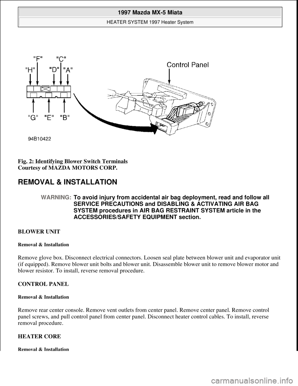
Fig. 2: Identifying Blower Switch Terminals
Courtesy of MAZDA MOTORS CORP.
REMOVAL & INSTALLATION
BLOWER UNIT
Removal & Installation
Remove glove box. Disconnect electrical connectors. Loosen seal plate between blower unit and evaporator unit
(if equipped). Remove blower unit bolts and blower unit. Disassemble blower unit to remove blower motor and
blower resistor. To install, reverse removal procedure.
CONTROL PANEL
Removal & Installation
Remove rear center console. Remove vent outlets from center panel. Remove center panel. Remove control
panel screws, and pull control panel from center panel. Disconnect heater control cables. To install, reverse
removal procedure.
HEATER CORE
Removal & Installation
WARNING:To avoid injury from accidental air bag deployment, read and follow all
SERVICE PRECAUTIONS and DISABLING & ACTIVATING AIR BAG
SYSTEM procedures in AIR BAG RESTRAINT SYSTEM article in the
ACCESSORIES/SAFETY EQUIPMENT section.
1997 Mazda MX-5 Miata
HEATER SYSTEM 1997 Heater System
Microsoft
Sunday, July 05, 2009 1:46:56 PMPage 4 © 2005 Mitchell Repair Information Company, LLC.