Page 216 of 514

2. Disconnect throttle cable. Remove fuel lines from fuel rail and pressure regulator. Remove throttle body
intake duct housing and throttle body. Remove by-pass air control valve and solenoid valves. Remove
upper intake manifold (if equipped).
3. Remove intake manifold support bracket from underneath manifold. Disconnect injector harness
connectors, and remove injectors/fuel rail assembly. Remove intake manifold and gasket.
Installation
1. Ensure all gasket surfaces are clean and flat. Using NEW gasket, install intake manifold to cylinder head.
Tighten manifold bolts/nuts evenly to specification, starting from center bolt and alternating outward. See
TORQUE SPECIFICATIONS
. Install support bracket underneath intake manifold.
2. Install gasket and upper intake manifold (if equipped). Tighten bolts/nuts evenly to specification,
alternating from top to bottom. See TORQUE SPECIFICATIONS
.
3. To complete installation, reverse removal procedure. Ensure throttle cable has .04-.12" (1-3 mm) free
play. Ensure injectors twist freely and are not cocked in insulator "O" rings. Refill engine with coolant.
EXHAUST MANIFOLD
Removal & Installation
1. Remove air cleaner intake duct from top of radiator/fan assembly (if equipped). Disconnect oxygen
sensor. Remove heat shields. Disconnect down pipe from exhaust manifold. Remove exhaust manifold.
2. To install, reverse removal procedure. Ensure all mating surfaces are clean and flat. Install NEW exhaust
manifold gasket to cylinder head. Tighten manifold bolts evenly to specification, starting from center bolt
and alternating outward. See TORQUE SPECIFICATIONS
.
CYLINDER HEAD
Removal
1. Release residual pressure from fuel system. See FUEL PRESSURE RELEASE & PRIMING . Drain
engine coolant. Note locations and disconnect all necessary electrical connectors, ground wires, vacuum
hoses, fuel hoses, coolant hoses and control cables for cylinder head removal. Plug all fuel hoses to avoid
leakage.
2. Remove spark plug wires from spark plugs. Remove all drive belts. Remove water pump pulley. Remove
timing belt. See TIMING BELT
. Remove camshaft/rocker cover.
3. Remove front exhaust pipe. Remove intake manifold support bracket. Loosen all cylinder head bolts
evenly, in 3 steps, in reverse of tightening sequence. See Fig. 7
. Remove bolts and cylinder head
assembly.
Inspection
Carefully clean carbon and gasket material from all mating surfaces. Clean threads of cylinder head bolts. Use a
tap to clean threads in engine block. Check cylinder head for warpage. Resurface or replace head if it is not
within specification. Check valve train components. Replace or resurface components if they are not within
1997 Mazda MX-5 Miata
1997-98 ENGINES 1.8L 4-Cylinder
Microsoft
Sunday, July 05, 2009 1:55:15 PMPage 10 © 2005 Mitchell Repair Information Company, LLC.
Page 242 of 514

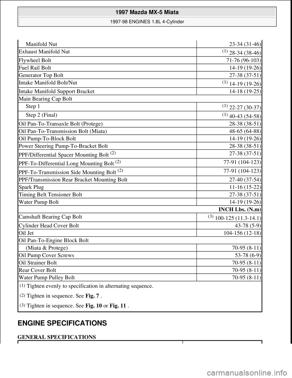
ENGINE SPECIFICATIONS
GENERAL SPECIFICATIONS
Manifold Nut23-34 (31-46)
Exhaust Manifold Nut(1) 28-34 (38-46)
Flywheel Bolt71-76 (96-103)
Fuel Rail Bolt14-19 (19-26)
Generator Top Bolt27-38 (37-51)
Intake Manifold Bolt/Nut(1) 14-19 (19-26)
Intake Manifold Support Bracket14-18 (19-25)
Main Bearing Cap Bolt
Step 1(1) 22-27 (30-37)
Step 2 (Final)(1) 40-43 (54-58)
Oil Pan-To-Transaxle Bolt (Protege)28-38 (38-51)
Oil Pan-To-Transmission Bolt (Miata)48-65 (64-88)
Oil Pump-To-Block Bolt14-19 (19-26)
Power Steering Pump-To-Bracket Bolt28-38 (38-51)
PPF/Differential Spacer Mounting Bolt (2) 27-38 (37-51)
PPF-To-Differential Long Mounting Bolt (2) 77-91 (104-123)
PPF-To-Transmission Side Mounting Bolt (2) 77-91 (104-123)
PPF/Transmission Rear Bracket Mounting Bolt27-40 (37-54)
Spark Plug11-16 (15-22)
Timing Belt Tensioner Bolt27-38 (37-51)
Water Pump Bolt14-19 (19-26)
INCH Lbs. (N.m)
Camshaft Bearing Cap Bolt(3) 100-125 (11.3-14.1)
Cylinder Head Cover Bolt43-78 (5-9)
Oil Jet104-156 (12-18)
Oil Pan-To-Engine Block Bolt
(Miata & Protege)70-95 (8-11)
Oil Pump Cover Screws53-78 (6-9)
Oil Strainer Bolt70-95 (8-11)
Rear Cover Bolt70-95 (8-11)
Water Pump Pulley Bolt70-95 (8-11)
(1)Tighten evenly to specification in alternating sequence.
(2)Tighten in sequence. See Fig. 7 .
(3)Tighten in sequence. See Fig. 10 or Fig. 11 .
1997 Mazda MX-5 Miata
1997-98 ENGINES 1.8L 4-Cylinder
Microsoft
Sunday, July 05, 2009 1:55:15 PMPage 36 © 2005 Mitchell Repair Information Company, LLC.
Page 326 of 514

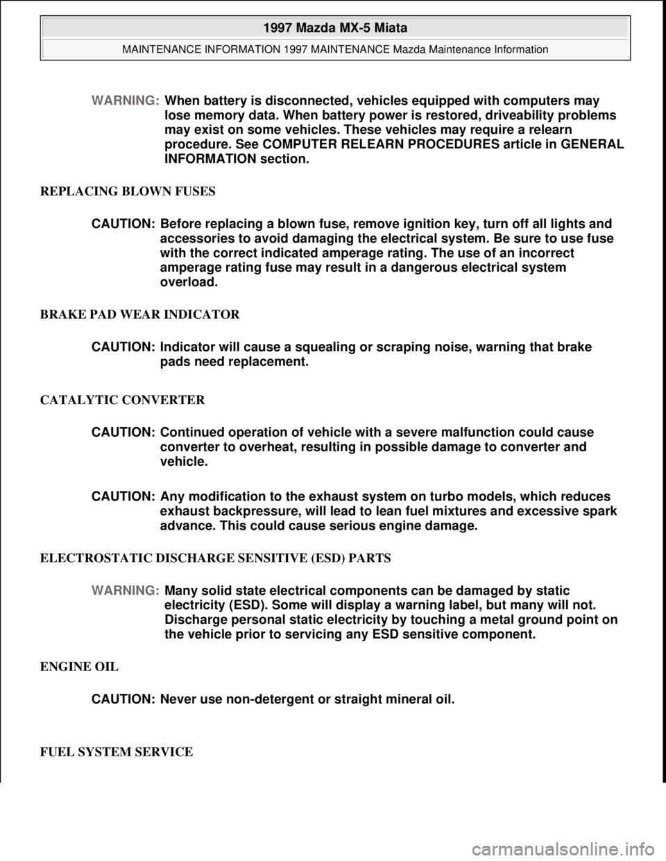
REPLACING BLOWN FUSES
BRAKE PAD WEAR INDICATOR
CATALYTIC CONVERTER
ELECTROSTATIC DISCHARGE SENSITIVE (ESD) PARTS
ENGINE OIL
FUEL SYSTEM SERVICE WARNING:When battery is disconnected, vehicles equipped with computers may
lose memory data. When battery power is restored, driveability problems
may exist on some vehicles. These vehicles may require a relearn
procedure. See COMPUTER RELEARN PROCEDURES article in GENERAL
INFORMATION section.
CAUTION: Before replacing a blown fuse, remove ignition key, turn off all lights and
accessories to avoid damaging the electrical system. Be sure to use fuse
with the correct indicated amperage rating. The use of an incorrect
amperage rating fuse may result in a dangerous electrical system
overload.
CAUTION: Indicator will cause a squealing or scraping noise, warning that brake
pads need replacement.
CAUTION: Continued operation of vehicle with a severe malfunction could cause
converter to overheat, resulting in possible damage to converter and
vehicle.
CAUTION: Any modification to the exhaust system on turbo models, which reduces
exhaust backpressure, will lead to lean fuel mixtures and excessive spark
advance. This could cause serious engine damage.
WARNING:Many solid state electrical components can be damaged by static
electricity (ESD). Some will display a warning label, but many will not.
Discharge personal static electricity by touching a metal ground point on
the vehicle prior to servicing any ESD sensitive component.
CAUTION: Never use non-detergent or straight mineral oil.
1997 Mazda MX-5 Miata
MAINTENANCE INFORMATION 1997 MAINTENANCE Mazda Maintenance Information
Microsoft
Sunday, July 05, 2009 1:41:19 PMPage 6 © 2005 Mitchell Repair Information Company, LLC.