1997 MAZDA MIATA ignition
[x] Cancel search: ignitionPage 72 of 514

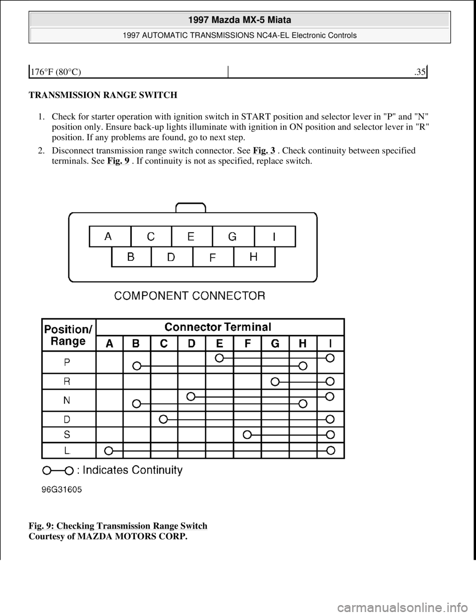
TRANSMISSION RANGE SWITCH
1. Check for starter operation with ignition switch in START position and selector lever in "P" and "N"
position only. Ensure back-up lights illuminate with ignition in ON position and selector lever in "R"
position. If any problems are found, go to next step.
2. Disconnect transmission range switch connector. See Fig. 3
. Check continuity between specified
terminals. See Fig. 9
. If continuity is not as specified, replace switch.
Fig. 9: Checking Transmission Range Switch
Courtesy of MAZDA MOTORS CORP.
176°F (80°C).35
1997 Mazda MX-5 Miata
1997 AUTOMATIC TRANSMISSIONS NC4A-EL Electronic Controls
Microsoft
Sunday, July 05, 2009 1:35:04 PMPage 24 © 2005 Mitchell Repair Information Company, LLC.
Page 73 of 514

TCM TERMINAL VOLTAGE TESTS
Turn ignition switch to ON position. Access TCM. TCM is mounted under left corner of dash, above fuse box.
DO NOT disconnect harness connector. Using DVOM, measure voltage. See Fig. 4
for terminal identification.
See Fig. 10
and Fig. 11 . After verifying that appropriate condition has been met, check voltage. If voltage is
not within specification, inspect component or appropriate circuit. If voltage is within specification, replace
TCM.
1997 Mazda MX-5 Miata
1997 AUTOMATIC TRANSMISSIONS NC4A-EL Electronic Controls
Microsoft
Sunday, July 05, 2009 1:35:04 PMPage 25 © 2005 Mitchell Repair Information Company, LLC.
Page 200 of 514

SOLENOIDS & SOLENOID VALVES
SOLENOIDS & SOLENOID VALVES
SWITCHES
SWITCHES
MISCELLANEOUS
MISCELLANEOUS
Vehicle Speed Sensor (VSS)On speedometer assembly.
Water Temperature Sender UnitOn center of engine. See Fig. 1 .
Washer Fluid Level SensorOn washer fluid reservoir. See Fig. 1 .
ComponentComponent Location
AT Interlock SolenoidIn steering column, near ignition switch. See Fig. 2 .
EC-AT Solenoid ValveOn left side of transmission.
EGR Solenoid Valve (Vacuum)On right side of engine compartment. See Fig. 1 .
EGR Solenoid Valve (Vent)On right side of engine compartment. See Fig. 1 .
Fourth Gear Solenoid ValveOn left side of transmission.
Idle Air Control ValveOn right side, front of engine compartment. See Fig. 1 .
PRC Solenoid ValveOn right side, front of engine. See Fig. 1 .
Purge Solenoid ValveOn right strut tower. See Fig. 1 .
ComponentComponent Location
Back-Up Lamp Switch (M/T)On right side of transmission. See Fig. 1 .
Brake SwitchOn bracket, above brake pedal. See Fig. 2 .
Buckle SwitchOn driver side seat belt buckle. See Fig. 3 .
Clutch Switch (M/T)On bracket, above clutch pedal. See Fig. 2 .
Hold SwitchUnder right side of center console.
Key Reminder SwitchIn steering column, near ignition switch.
Neutral Switch (M/T)On right side of transmission. See Fig. 1 .
Oil Pressure SwitchOn right side of engine. See Fig. 1 .
"P" Range SwitchUnder center console, on base of gear selector.
Parking Brake SwitchOn base of parking brake lever. See Fig. 4 .
Power Steering Pressure SwitchOn power steering pump assembly.
Refrigerant Pressure SwitchIn front of engine compartment, near radiator support. See Fig. 1 .
Starter Interlock Switch (M/T)On bracket, above clutch pedal. See Fig. 2 .
ThermoswitchUnder right side of dash.
Transmission Range SwitchOn left side of transmission.
ComponentComponent Location
1997 Mazda MX-5 Miata
1997 MAZDA MX-5 Miata
Microsoft
Sunday, July 05, 2009 1:54:00 PMPage 3 © 2005 Mitchell Repair Information Company, LLC.
Page 201 of 514

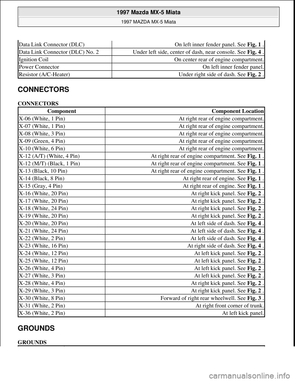
CONNECTORS
CONNECTORS
GROUNDS
GROUNDS
Data Link Connector (DLC)On left inner fender panel. See Fig. 1 .
Data Link Connector (DLC) No. 2Under left side, center of dash, near console. See Fig. 4 .
Ignition CoilOn center rear of engine compartment.
Power ConnectorOn left inner fender panel.
Resistor (A/C-Heater)Under right side of dash. See Fig. 2 .
ComponentComponent Location
X-06 (White, 1 Pin)At right rear of engine compartment.
X-07 (White, 1 Pin)At right rear of engine compartment.
X-08 (White, 3 Pin)At right rear of engine compartment.
X-09 (Green, 4 Pin)At right rear of engine compartment.
X-10 (White, 6 Pin)At right rear of engine compartment.
X-12 (A/T) (White, 4 Pin)At right rear of engine compartment. See Fig. 1 .
X-12 (M/T) (Black, 1 Pin)At right rear of engine compartment. See Fig. 1 .
X-13 (Black, 10 Pin)At right rear of engine compartment. See Fig. 1 .
X-14 (Black, 8 Pin)At right rear of engine. See Fig. 1 .
X-15 (Gray, 4 Pin)At right rear of engine. See Fig. 1 .
X-16 (White, 20 Pin)At right kick panel. See Fig. 2 .
X-17 (White, 20 Pin)At right kick panel. See Fig. 2 .
X-18 (White, 24 Pin)At right kick panel. See Fig. 2 .
X-19 (White, 20 Pin)At right kick panel. See Fig. 2 .
X-20 (White, 20 Pin)At left side of dash. See Fig. 4 .
X-21 (White, 24 Pin)At left side of dash. See Fig. 4 .
X-22 (White, 2 Pin)At left side of dash. See Fig. 4 .
X-23 (White, 16 Pin)At right side of dash. See Fig. 4 .
X-24 (White, 12 Pin)At left kick panel. See Fig. 2 .
X-25 (White, 12 Pin)At left kick panel. See Fig. 2 .
X-26 (White, 4 Pin)At left kick panel. See Fig. 2 .
X-27 (White, 3 Pin)At left kick panel. See Fig. 2 .
X-28 (White, 4 Pin)At right kick panel. See Fig. 2 .
X-29 (White, 3 Pin)At right kick panel. See Fig. 2 .
X-30 (White, 8 Pin)Forward of right rear wheelwell. See Fig. 3 .
X-31 (White, 2 Pin)At right front corner of trunk.
X-36 (White, 2 Pin)At left kick panel.
1997 Mazda MX-5 Miata
1997 MAZDA MX-5 Miata
Microsoft
Sunday, July 05, 2009 1:54:00 PMPage 4 © 2005 Mitchell Repair Information Company, LLC.
Page 207 of 514

1997-98 ENGINES
1.8L 4-Cylinder
ENGINE IDENTIFICATION
Engines can be identified by engine model and number. See ENGINE IDENTIFICATION CODE. On Miata,
engine model and number are stamped on flange at upper right rear of cylinder block deck, as viewed from
flywheel. On Protege, engine model and number are stamped on flange at upper left rear of cylinder block deck,
as viewed from flywheel.
ENGINE IDENTIFICATION CODE
ADJUSTMENTS
VALVE CLEARANCE ADJUSTMENT
REMOVAL & INSTALLATION
FUEL PRESSURE RELEASE & PRIMING
Releasing Pressure (Miata)
Locate and remove fuel pump relay from under left side of dash, near steering column. Start engine and allow to
stall. After engine stalls, attempt to restart engine to ensure no residual pressure exists. Turn ignition off and
reinstall fuel pump relay. When disconnecting fuel hoses, cover connection with shop rag to catch fuel leakage.
To avoid excessive cranking after servicing, prime fuel system before starting engine.
Releasing Pressure (Protege)
NOTE: For repair procedures not covered in this article, see ENGINE OVERHAUL
PROCEDURES article in GENERAL INFORMATION.
ApplicationCode
Miata & Protege (1.8L DOHC)BP
NOTE: Valve clearance is not adjustable. Some Hydraulic Lash Adjuster (HLA) noise
may occur during engine start-up. Noise should disappear after engine reaches
normal operating temperature. If noise persists and oil level is okay, change
engine oil. If oil change does not reduce noise, check with manufacturer for
modified HLA.
NOTE: For reassembly reference, label all electrical connectors, vacuum hoses and
fuel lines before removal. Also place mating marks on engine hood and other
major assemblies before removal.
1997 Mazda MX-5 Miata
1997-98 ENGINES 1.8L 4-Cylinder
1997 Mazda MX-5 Miata
1997-98 ENGINES 1.8L 4-Cylinder
Microsoft
Sunday, July 05, 2009 1:55:15 PMPage 1 © 2005 Mitchell Repair Information Company, LLC.
Microsoft
Sunday, July 05, 2009 1:55:19 PMPage 1 © 2005 Mitchell Repair Information Company, LLC.
Page 208 of 514

Remove rear seat cushions. Disconnect fuel pump connector. Start engine and allow to stall. After engine stalls,
attempt to restart engine to ensure no residual pressure exists. Turn ignition off and reconnect fuel pump
connector. When disconnecting fuel hoses, cover connection with shop rag to catch fuel leakage. To avoid
excessive cranking after servicing, prime fuel system before starting engine.
Priming System
Ensure fuel system is closed. Connect jumper wire between F/P and GND terminals of data link connector. See
Fig. 1
. Turn ignition on for about 10 seconds and check for fuel leaks. Turn ignition off and disconnect jumper
wire.
Fig. 1: Identifying Data Link Connector Terminals (Typical)
Courtesy of MAZDA MOTORS CORP.
COOLING SYSTEM BLEEDING
1. Slowly pour coolant into radiator at a rate of 1.1 qt. (1.0L) per minute maximum until coolant is level
with filler port. Fill coolant reservoir to "F" mark. Securely install radiator cap. Start engine.
2. Operate engine at idle until normal operating temperature is reached. If coolant level warning light
illuminates during warm-up, turn engine off and check drain plug and coolant hoses for leaks. Operate
engine at 2200-2800 RPM for 5 minutes. Stop engine and allow to cool.
3. Repeat steps 1) and 2). Check coolant level. If engine coolant is not level with filler neck, repeat entire
procedure. If engine coolant is level with filler neck, fill reservoir to "F" mark.
CAUTION: If engine overheats during procedure, system contains excessive air. Stop
engine and allow it to cool, then repeat step 1).
1997 Mazda MX-5 Miata
1997-98 ENGINES 1.8L 4-Cylinder
Microsoft
Sunday, July 05, 2009 1:55:15 PMPage 2 © 2005 Mitchell Repair Information Company, LLC.
Page 209 of 514

ENGINE
Removal (Miata)
1. Release residual pressure from fuel system. See FUEL PRESSURE RELEASE & PRIMING .
Disconnect negative battery cable from trunk-mounted battery. Reference mark and remove hood. Raise
vehicle and remove engine undercover. See Fig. 2
. Drain engine, transmission and cooling system fluids.
2. Remove transmission. For automatic transmission removal procedure, see REMOVAL &
INSTALLATION article in TRANSMISSION SERVICING. For manual transmission removal
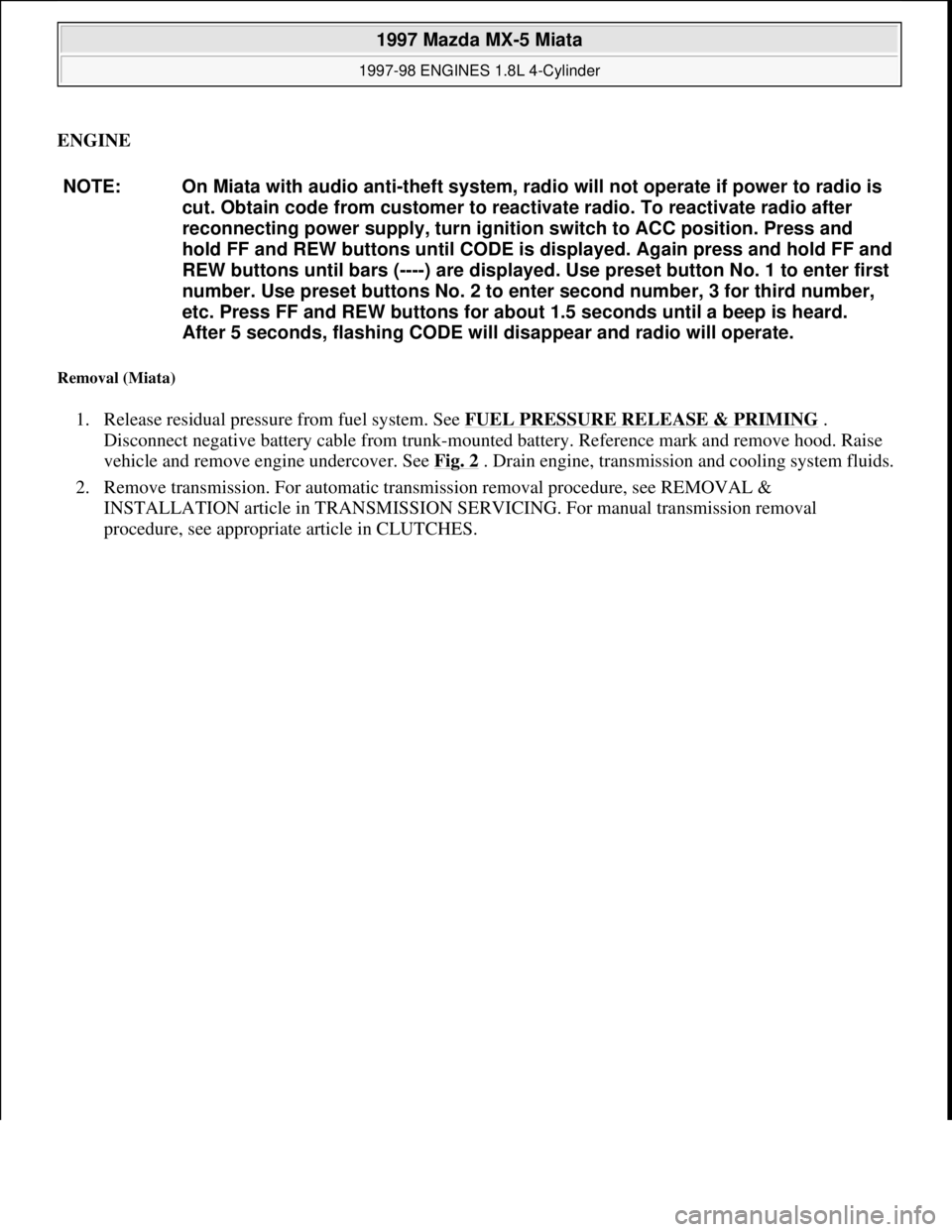
procedure, see appropriate article in CLUTCHES. NOTE: On Miata with audio anti-theft system, radio will not operate if power to radio is
cut. Obtain code from customer to reactivate radio. To reactivate radio after
reconnecting power supply, turn ignition switch to ACC position. Press and
hold FF and REW buttons until CODE is displayed. Again press and hold FF and
REW buttons until bars (----) are displayed. Use preset button No. 1 to enter first
number. Use preset buttons No. 2 to enter second number, 3 for third number,
etc. Press FF and REW buttons for about 1.5 seconds until a beep is heard.
After 5 seconds, flashing CODE will disappear and radio will operate.
1997 Mazda MX-5 Miata
1997-98 ENGINES 1.8L 4-Cylinder
Microsoft
Sunday, July 05, 2009 1:55:15 PMPage 3 © 2005 Mitchell Repair Information Company, LLC.
Page 304 of 514

Fig. 1: Exploded View Of Heater Unit
Courtesy of MAZDA MOTORS CORP.
ADJUSTMENTS
AIRFLOW MODE DOOR
Set airflow mode control lever at vent position. Disconnect control cable at airflow mode door lever. See Fig.
1 . Extend airflow mode door lever until it stops. Attach control cable to door lever. Secure cable using clip.
Ensure control lever slides freely between defrost and vent positions.
AIR-MIX (TEMPERATURE BLEND) DOOR
Set temperature control lever at maximum hot setting. Disconnect control cable at air-mix door lever. See Fig.
1 . Extend air-mix door lever until it stops. Attach control cable to door lever. Secure cable using clip. Ensure
control lever slides freely between hot and cold settings.
FRESH/RECIRCULATED AIR DOOR
Set fresh/recirculated air control lever at fresh air setting. Disconnect control cable at fresh/recirculated air door
lever. Retract recirculated/fresh air door lever until it stops. Attach control cable to door lever. Secure cable
using clip. Ensure control lever slides freely between recirculated air and fresh air settings.
TESTING
BLOWER MOTOR CIRCUIT
1. Check 30-amp HEATER fuse in passenger compartment fuse block. If fuse is okay, go to next step. If
fuse is burnt, check for short circuit in wiring harness and repair as necessary. Replace fuse.
2. Turn ignition on. Turn blower switch to 4th position (high). Using voltmeter, backprobe Blue wire
terminal of blower motor connector on bottom of blower case. If battery voltage exists, go to next step. If
battery voltage is not present, repair wiring harness between circuit breaker or fuse and blower motor.
3. Ensure ignition is on. Backprobe Blue wire terminal of blower resistor 1-pin connector. If battery voltage
exists, go to next step. If battery voltage is not present, replace blower motor.
4. Backprobe Blue/White wire terminal, Blue/Red wire terminal, Blue/Green wire terminal and Blue/Yellow
wire terminal of blower resistor 4-pin connector. If battery voltage exists, go to next step. If battery
voltage is not present at any terminal, replace blower resistor.
5. Turn blower switch to 4th position (high). Backprobe Black wire terminal of blower switch connector. If
battery voltage is not present, go to next step. If battery voltage exists, repair Black wire between blower
switch and chassis
ground. WARNING:To avoid injury from accidental air bag deployment, read and follow all
SERVICE PRECAUTIONS and DISABLING & ACTIVATING AIR BAG
SYSTEM procedures in AIR BAG RESTRAINT SYSTEM article in the
ACCESSORIES/SAFETY EQUIPMENT section.
1997 Mazda MX-5 Miata
HEATER SYSTEM 1997 Heater System
Microsoft
Sunday, July 05, 2009 1:46:56 PMPage 2 © 2005 Mitchell Repair Information Company, LLC.