1997 MAZDA MIATA warning light
[x] Cancel search: warning lightPage 329 of 514
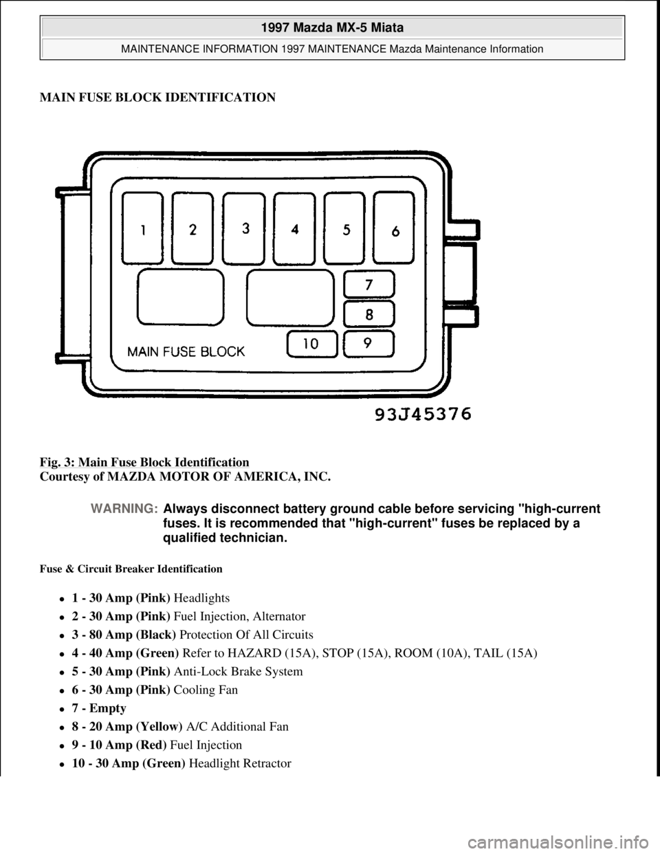
MAIN FUSE BLOCK IDENTIFICATION
Fig. 3: Main Fuse Block Identification
Courtesy of MAZDA MOTOR OF AMERICA, INC.
Fuse & Circuit Breaker Identification
1 - 30 Amp (Pink) Headlights
2 - 30 Amp (Pink) Fuel Injection, Alternator
3 - 80 Amp (Black) Protection Of All Circuits
4 - 40 Amp (Green) Refer to HAZARD (15A), STOP (15A), ROOM (10A), TAIL (15A)
5 - 30 Amp (Pink) Anti-Lock Brake System
6 - 30 Amp (Pink) Cooling Fan
7 - Empty
8 - 20 Amp (Yellow) A/C Additional Fan
9 - 10 Amp (Red) Fuel Injection
10 - 30 Amp (Green) Headlight Retractor
WARNING:Always disconnect battery ground cable before servicing "high-current
fuses. It is recommended that "high-current" fuses be replaced by a
qualified technician.
1997 Mazda MX-5 Miata
MAINTENANCE INFORMATION 1997 MAINTENANCE Mazda Maintenance Information
Microsoft
Sunday, July 05, 2009 1:41:19 PMPage 9 © 2005 Mitchell Repair Information Company, LLC.
Page 331 of 514
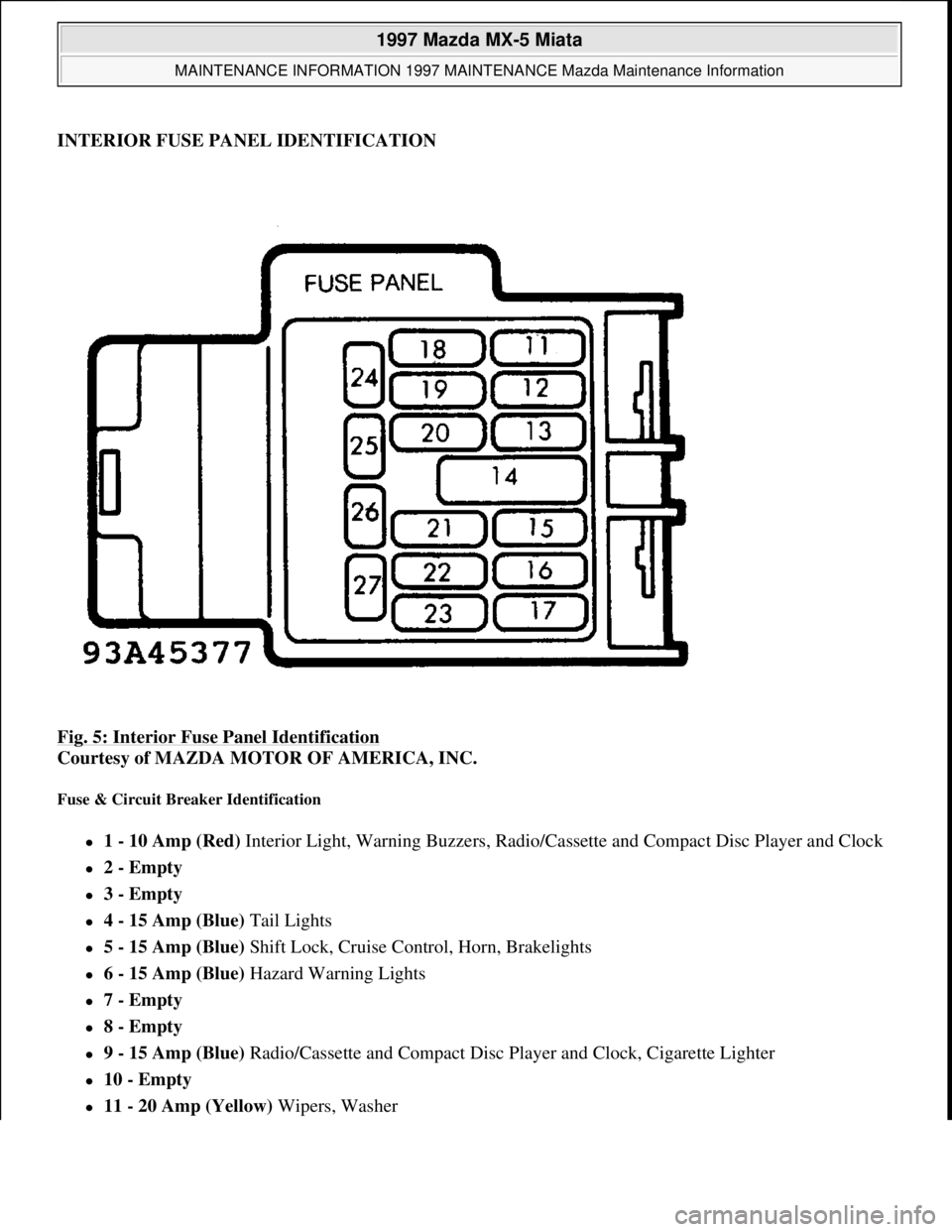
INTERIOR FUSE PANEL IDENTIFICATION
Fig. 5: Interior Fuse Panel Identification
Courtesy of MAZDA MOTOR OF AMERICA, INC.
Fuse & Circuit Breaker Identification
1 - 10 Amp (Red) Interior Light, Warning Buzzers, Radio/Cassette and Compact Disc Player and Clock
2 - Empty
3 - Empty
4 - 15 Amp (Blue) Tail Lights
5 - 15 Amp (Blue) Shift Lock, Cruise Control, Horn, Brakelights
6 - 15 Amp (Blue) Hazard Warning Lights
7 - Empty
8 - Empty
9 - 15 Amp (Blue) Radio/Cassette and Compact Disc Player and Clock, Cigarette Lighter
10 - Empty
11 - 20 Amp (Yellow) Wipers, Washer
1997 Mazda MX-5 Miata
MAINTENANCE INFORMATION 1997 MAINTENANCE Mazda Maintenance Information
Microsoft
Sunday, July 05, 2009 1:41:19 PMPage 11 © 2005 Mitchell Repair Information Company, LLC.
Page 332 of 514
12 - 30 Amp (Green) Power Windows
13 - Empty
14 - Empty 15 - 15 Amp (Blue) Gauges, Warning Lights, Turn-Signal Lights, Cruise Control
16 - 15 Amp (Blue) Cooling Fan
17 - 30 Amp (Pink) Heater
18 - Empty
19 - Empty
20 - 10 Amp Defog (Some Models)
21 - 10 Amp Antenna (Some Models)
22 - Empty
1997 Mazda MX-5 Miata
MAINTENANCE INFORMATION 1997 MAINTENANCE Mazda Maintenance Information
Microsoft
Sunday, July 05, 2009 1:41:19 PMPage 12 © 2005 Mitchell Repair Information Company, LLC.
Page 399 of 514
STEERING COLUMN
1995-97 STEERING Mazda Motors Corp. - Steering Columns
DESCRIPTION & OPERATION
Steering columns are designed to be collapsible upon impact. The steering column consists of solid steering
shaft with a lower joint assembly. Some models are equipped with tilt steering. Turn signal, headlight, ignition
and windshield washer/wiper switches are mounted on column. Switches can be serviced by removing steering
wheel and column covers. All models are equipped with air bag restraint system consisting of an driver air bag
module, passenger air bag module (except 1995 MPV and 1995 Protege) and clockspring connector assembly
located in the steering column.
SYSTEM OPERATION CHECK
1. Turn ignition switch to ON or START position. AIR BAG warning light in instrument cluster should
illuminate for about 4-8 seconds, and then turn off. This indicates air bag system is functioning properly.
2. If any of the following conditions exists, air bag system is malfunctioning and requires servicing.
AIR BAG warning light does not illuminate as specified.
AIR BAG warning light remains illuminated for more than 8 seconds.
AIR BAG warning light illuminates while driving.
3. If air bag system components are replaced for any reason, air bag system must be checked for proper
function after repair. Repeat step 1). If AIR BAG warning light does not illuminate as specified, air bag
system is malfunctioning and servicing is required. See AIR BAG RESTRAINT SYSTEM article.
SERVICE PRECAUTIONS
Observe the following precautions when servicing air bag system.
Disable air bag system before servicing any air bag system or steering column component. See AIR BAG
DISABLING & ACTIVATING .
After disabling air bag system, wait at least one minute before servicing. Air bag system voltage is
maintained for approximately one minute after system is disabled. Failure to wait one minute before
servicing system may cause accidental air bag deployment and possible personal injury.
Obtain radio code number from customer and deactivate radio anti-theft function (if equipped) before
disconnecting battery.
Because of the critical operation requirements of system, DO NOT service any air bag system
component. Repairs are made by replacement only.
DO NOT use an ohmmeter to check resistance of air bag module, as it may cause air bag deployment.
When carrying a live (undeployed) air bag module, ensure trim cover is pointed away from your body. WARNING:To avoid injury from accidental air bag deployment, read and carefully
follow all WARNINGS and SERVICE PRECAUTIONS
.
1997 Mazda MX-5 Miata
STEERING COLUMN 1995-97 STEERING Mazda Motors Corp. - Steering Columns
1997 Mazda MX-5 Miata
STEERING COLUMN 1995-97 STEERING Mazda Motors Corp. - Steering Columns
Microsoft
Sunday, July 05, 2009 1:40:02 PMPage 1 © 2005 Mitchell Repair Information Company, LLC.
Microsoft
Sunday, July 05, 2009 1:40:07 PMPage 1 © 2005 Mitchell Repair Information Company, LLC.
Page 400 of 514
This minimizes chance of injury in the event of accidental air bag deployment.
When placing a live air bag module on any surface, always face trim cover upward to reduce motion of
module if it is accidentally deployed.
If an open circuit is present, replace entire wiring harness. DO NOT attempt to repair wire(s).
Air bag system clockspring MUST be aligned in neutral position, since its rotation ability is limited. DO
NOT turn steering wheel or column after removal of steering gear.
A double-lock mechanism is used on clockspring connectors. DO NOT use excessive force when
disconnecting connectors, as damage to connector may occur.
AIR BAG DISABLING & ACTIVATING
DISABLING SYSTEM (MIATA, MILLENIA, MPV, MX-6, PROTEGE & 626)
1. Obtain radio code from customer and deactivate audio anti-theft function (if equipped). Turn ignition off.
Disconnect and shield negative battery cable. Wait at least one minute for back-up power supply to be
depleted. Remove lower cover panel(s) below left side of instrument panel.
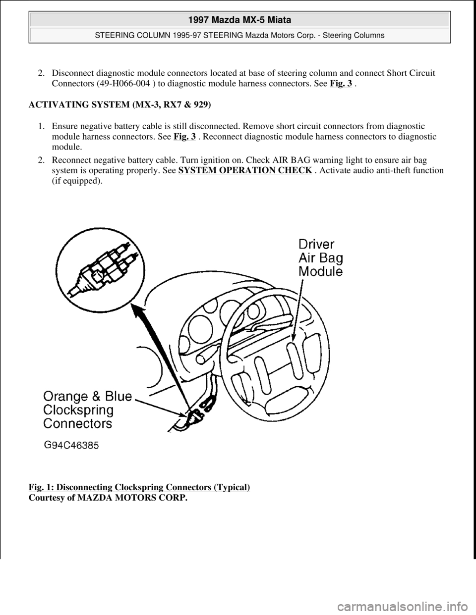
2. On MPV, remove lower steering column shroud. On all models, disconnect Orange and Blue clockspring
connectors for driver air bag module. See Fig. 1
. On all models except 1995 Protege and 1995 MPV,
remove glove box compartment. Disconnect Orange and Blue connectors for passenger air bag module.
See Fig. 2
.
ACTIVATING SYSTEM (MIATA, MILLENIA, MPV, MX-6, PROTEGE & 626)
1. Ensure negative battery cable is still disconnected. On all models except 1995 Protege and 1995 MPV,
reconnect Orange and Blue connector for passenger air bag module. Install glove box compartment.
2. On all models, reconnect Orange and Blue clockspring connectors for driver air bag module. Install lower
cover panel(s). On MPV, install lower steering column shroud. On all models, reconnect negative battery
cable.
3. Turn ignition on. Check AIR BAG warning light to ensure air bag system is operating properly. See
SYSTEM OPERATION CHECK
. Activate audio anti-theft function (if equipped).
DISABLING SYSTEM (MX-3, RX7 & 929)
1. Obtain radio code from customer and deactivate audio anti-theft function. Turn ignition off. Disconnect
and shield ne
gative battery cable. Wait at least one minute for back-up power supply to be depleted. WARNING:Wait about one minute after disabling air bag system before servicing. Air
bag system voltage is maintained for about one minute after system is
disabled. Failure to wait one minute before servicing system may cause
accidental air bag deployment and possible personal injury.
CAUTION: When battery is disconnected, vehicle computer and memory systems
may lose memory data. Driveability problems may exist until computer
systems have completed a relearn cycle.
1997 Mazda MX-5 Miata
STEERING COLUMN 1995-97 STEERING Mazda Motors Corp. - Steering Columns
Microsoft
Sunday, July 05, 2009 1:40:02 PMPage 2 © 2005 Mitchell Repair Information Company, LLC.
Page 401 of 514
2. Disconnect diagnostic module connectors located at base of steering column and connect Short Circuit
Connectors (49-H066-004 ) to diagnostic module harness connectors. See Fig. 3
.
ACTIVATING SYSTEM (MX-3, RX7 & 929)
1. Ensure negative battery cable is still disconnected. Remove short circuit connectors from diagnostic
module harness connectors. See Fig. 3
. Reconnect diagnostic module harness connectors to diagnostic
module.
2. Reconnect negative battery cable. Turn ignition on. Check AIR BAG warning light to ensure air bag
system is operating properly. See SYSTEM OPERATION CHECK
. Activate audio anti-theft function
(if equipped).
Fig. 1: Disconnecting Clockspring Connectors (Typical)
Courtesy of MAZDA MOTORS CORP.
1997 Mazda MX-5 Miata
STEERING COLUMN 1995-97 STEERING Mazda Motors Corp. - Steering Columns
Microsoft
Sunday, July 05, 2009 1:40:02 PMPage 3 © 2005 Mitchell Repair Information Company, LLC.
Page 405 of 514
To install, reverse removal procedure. Tighten driver air bag module bolts or nuts to specification. See
TORQUE SPECIFICATIONS
table. Activate air bag system. See AIR BAG DISABLING &
ACTIVATING . Check AIR BAG warning light to ensure system is functioning properly. See SYSTEM
OPERATION CHECK .
STEERING WHEEL
Removal
Set front wheels in straight-ahead position. Disconnect negative battery cable. Disable air bag system. See AIR
BAG DISABLING & ACTIVATING . Remove driver air bag module. See DRIVER AIR BAG MODULE .
Mark steering wheel and shaft for reassembly reference. Remove steering wheel nut. Using appropriate puller,
remove steering wheel.
Installation
Ensure front wheels are in straight-ahead position. Install steering wheel, ensuring reference marks are aligned.
Tighten steering wheel nut to specification. See TORQUE SPECIFICATIONS
table. To install remaining
components, reverse removal procedure.
COMBINATION SWITCH
Removal
1. Before proceeding, follow air bag service precautions. See SERVICE PRECAUTIONS. Disable air bag
system. See AIR BAG DISABLING & ACTIVATING
.
2. Remove driver air bag module. See DRIVER AIR BAG MODULE
. Remove steering wheel. See
STEERING WHEEL
. Remove upper and lower steering column covers. Disconnect combination
switch electrical connectors. Remove combination switch screws.
3. Remove clockspring and combination switch as an assembly. Separate clockspring from combination
switch.
Installation
1. To install, reverse removal procedure. Ensure front wheels are in straight-ahead position. Before
installing steering wheel, center clockspring. See CLOCKSPRING CENTERING
under
ADJUSTMENTS. Tighten steering wheel nut to specification. See TORQUE SPECIFICATIONS
table.
2. After installation, activate air bag system. See AIR BAG DISABLING & ACTIVATING
. Check AIR
BAG warning light to ensure system is functioning properly. See SYSTEM OPERATION CHECK
.
IGNITION SWITCH/STEERING LOCK ASSEMBLY
Removal & Installation
1. Remove driver air bag module, steering wheel and combination switch. See the following:
DRIVER AIR BAG MODULE.
1997 Mazda MX-5 Miata
STEERING COLUMN 1995-97 STEERING Mazda Motors Corp. - Steering Columns
Microsoft
Sunday, July 05, 2009 1:40:02 PMPage 7 © 2005 Mitchell Repair Information Company, LLC.