Page 380 of 514

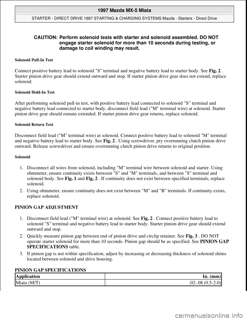
Solenoid Pull-In Test
Connect positive battery lead to solenoid "S" terminal and negative battery lead to starter body. See Fig. 2 .
Starter pinion drive gear should extend outward and stop. If starter pinion drive gear does not extend, replace
solenoid.
Solenoid Hold-In Test
After performing solenoid pull-in test, with positive battery lead connected to solenoid "S" terminal and
negative battery lead connected to starter body, disconnect field lead ("M" terminal wire) at solenoid. Starter
pinion drive gear should remain extended. If starter pinion drive gear returns, replace solenoid.
Solenoid Return Test
Disconnect field lead ("M" terminal wire) at solenoid. Connect positive battery lead to solenoid "M" terminal
and negative battery lead to starter body. See Fig. 2
. Using screwdriver, pry overrunning clutch pinion drive
outward. Release screwdriver and ensure overrunning clutch pinion drive returns to original position.
Solenoid
1. Disconnect all wires from solenoid, including "M" terminal wire between solenoid and starter. Using
ohmmeter, ensure continuity exists between "S" and "M" terminals, and between "S" terminal and
solenoid body. See Fig. 1
and Fig. 2 . If continuity does not exist between specified terminals, replace
solenoid.
2. Using ohmmeter, ensure continuity does not exist between "M" and "B" terminals. If continuity exists,
replace solenoid.
PINION GAP ADJUSTMENT
1. Disconnect field lead ("M" terminal wire) at solenoid. See Fig. 2
. Connect positive battery lead to
solenoid "S" terminal and negative battery lead to starter body. Starter pinion drive gear should extend
outward and stop.
2. Quickly measure pinion gap between end of pinion drive and circlip retainer. See Fig. 3
. DO NOT
operate starter solenoid for more than 10 seconds. Pinion gap should be as specified. See PINION GAP
SPECIFICATIONS table.
3. If pinion gap is not within specification, adjust by increasing or decreasing thickness of solenoid shims
located between solenoid and drive housing.
PINION GAP SPECIFICATIONS CAUTION: Perform solenoid tests with starter and solenoid assembled. DO NOT
engage starter solenoid for more than 10 seconds during testing, or
damage to coil winding may result.
ApplicationIn. (mm)
Miata (M/T).02-.08 (0.5-2.0)
1997 Mazda MX-5 Miata
STARTER - DIRECT DRIVE 1997 STARTING & CHARGING SYSTEMS Mazda - Starters - Direct Drive
Microsoft
Sunday, July 05, 2009 1:56:16 PMPage 5 © 2005 Mitchell Repair Information Company, LLC.
Page 391 of 514

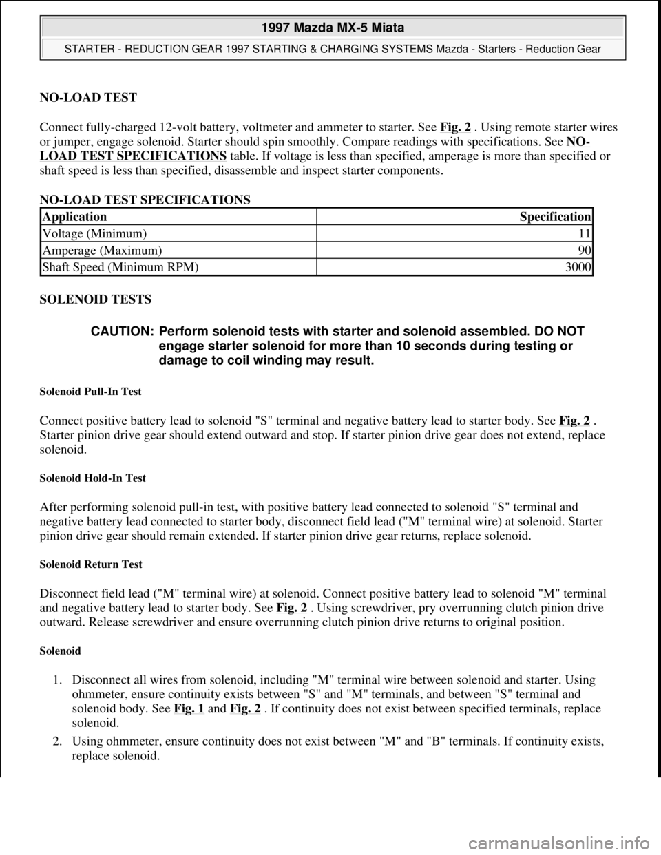
NO-LOAD TEST
Connect fully-charged 12-volt battery, voltmeter and ammeter to starter. See Fig. 2
. Using remote starter wires
or jumper, engage solenoid. Starter should spin smoothly. Compare readings with specifications. See NO
-
LOAD TEST SPECIFICATIONS table. If voltage is less than specified, amperage is more than specified or
shaft speed is less than specified, disassemble and inspect starter components.
NO-LOAD TEST SPECIFICATIONS
SOLENOID TESTS
Solenoid Pull-In Test
Connect positive battery lead to solenoid "S" terminal and negative battery lead to starter body. See Fig. 2 .
Starter pinion drive gear should extend outward and stop. If starter pinion drive gear does not extend, replace
solenoid.
Solenoid Hold-In Test
After performing solenoid pull-in test, with positive battery lead connected to solenoid "S" terminal and
negative battery lead connected to starter body, disconnect field lead ("M" terminal wire) at solenoid. Starter
pinion drive gear should remain extended. If starter pinion drive gear returns, replace solenoid.
Solenoid Return Test
Disconnect field lead ("M" terminal wire) at solenoid. Connect positive battery lead to solenoid "M" terminal
and negative battery lead to starter body. See Fig. 2
. Using screwdriver, pry overrunning clutch pinion drive
outward. Release screwdriver and ensure overrunning clutch pinion drive returns to original position.
Solenoid
1. Disconnect all wires from solenoid, including "M" terminal wire between solenoid and starter. Using
ohmmeter, ensure continuity exists between "S" and "M" terminals, and between "S" terminal and
solenoid body. See Fig. 1
and Fig. 2 . If continuity does not exist between specified terminals, replace
solenoid.
2. Using ohmmeter, ensure continuity does not exist between "M" and "B" terminals. If continuity exists,
replace solenoid.
ApplicationSpecification
Voltage (Minimum)11
Amperage (Maximum)90
Shaft Speed (Minimum RPM)3000
CAUTION: Perform solenoid tests with starter and solenoid assembled. DO NOT
engage starter solenoid for more than 10 seconds during testing or
damage to coil winding may result.
1997 Mazda MX-5 Miata
STARTER - REDUCTION GEAR 1997 STARTING & CHARGING SYSTEMS Mazda - Starters - Reduction Gear
Microsoft
Sunday, July 05, 2009 1:56:43 PMPage 5 © 2005 Mitchell Repair Information Company, LLC.
Page 392 of 514
PINION GAP ADJUSTMENT
1. Disconnect field lead ("M" terminal wire) at solenoid. See Fig. 2
. Connect positive battery lead to
solenoid "S" terminal and negative battery lead to starter body. Starter pinion drive gear should extend
outward and stop.
2. Quickly measure pinion gap between end of pinion drive and circlip retainer. See Fig. 3
. DO NOT
operate starter solenoid for more than 10 seconds. Pinion gap should be as specified. See PINION GAP
SPECIFICATIONS table.
3. If pinion gap is not within specification, adjust by increasing or decreasing thickness of solenoid shims
located between solenoid and drive housing.
PINION GAP SPECIFICATIONS
ApplicationIn. (mm)
Miata A/T.02-.08 (0.5-2.0)
1997 Mazda MX-5 Miata
STARTER - REDUCTION GEAR 1997 STARTING & CHARGING SYSTEMS Mazda - Starters - Reduction Gear
Microsoft
Sunday, July 05, 2009 1:56:43 PMPage 6 © 2005 Mitchell Repair Information Company, LLC.