Page 238 of 514
Fig. 21: Cross-Sectional View Of Engine Oil Circuit
Courtesy of MAZDA MOTORS CORP.
Crankcase Capacity
See ENGINE OIL CRANKCASE CAPACITY .
Oil Pressure
With engine at operating temperature, oil pressure should be 15-28 psi (1.0-2.0 kg/cm2 ) at 1000 RPM, and 43-
57 psi(3.0-4.0 kg/cm
2 ) at 3000 RPM.
Oil Pressure Relief Valve
Pressure relief valve opening pressure is 50-64 psi (3.5-4.5 kg/cm2). Pressure relief valve is located in oil pump
body and is not adjustable.
ENGINE OIL CRANKCASE CAPACITY
1997 Mazda MX-5 Miata
1997-98 ENGINES 1.8L 4-Cylinder
Microsoft
Sunday, July 05, 2009 1:55:15 PMPage 32 © 2005 Mitchell Repair Information Company, LLC.
Page 239 of 514

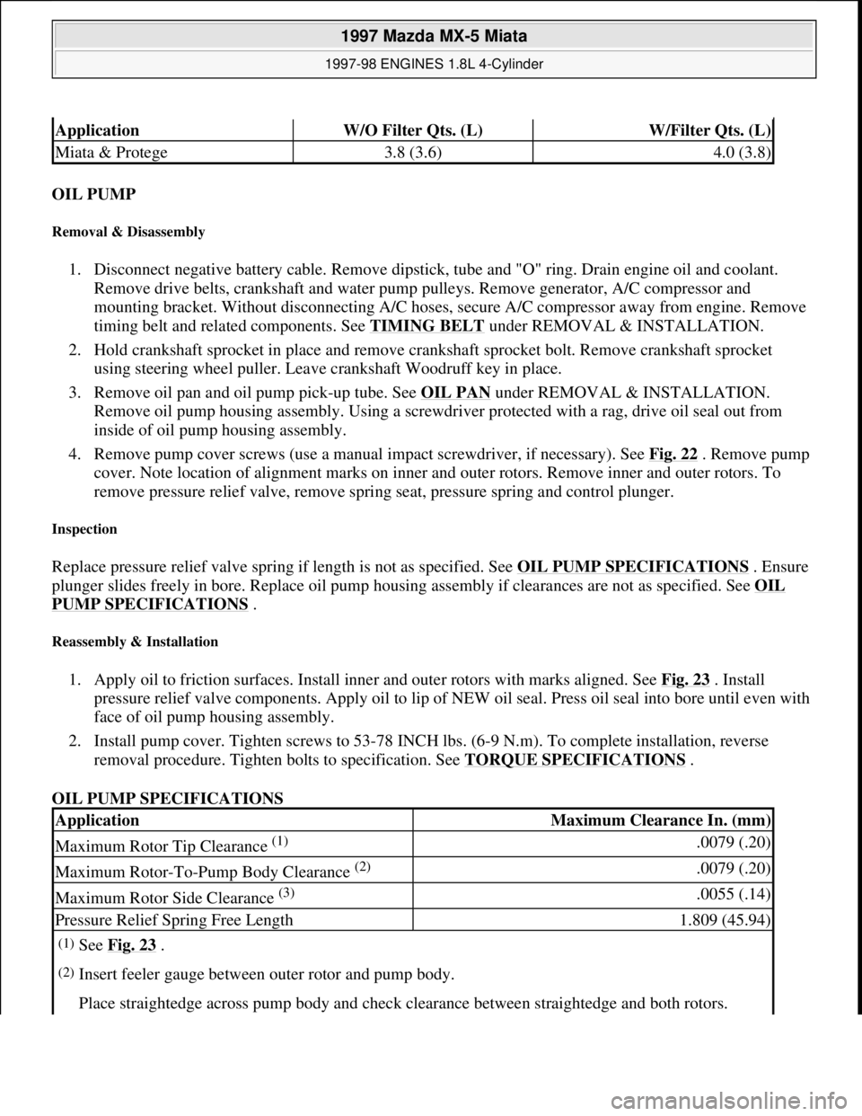
OIL PUMP
Removal & Disassembly
1. Disconnect negative battery cable. Remove dipstick, tube and "O" ring. Drain engine oil and coolant.
Remove drive belts, crankshaft and water pump pulleys. Remove generator, A/C compressor and
mounting bracket. Without disconnecting A/C hoses, secure A/C compressor away from engine. Remove
timing belt and related components. See TIMING BELT
under REMOVAL & INSTALLATION.
2. Hold crankshaft sprocket in place and remove crankshaft sprocket bolt. Remove crankshaft sprocket
using steering wheel puller. Leave crankshaft Woodruff key in place.
3. Remove oil pan and oil pump pick-up tube. See OIL PAN
under REMOVAL & INSTALLATION.
Remove oil pump housing assembly. Using a screwdriver protected with a rag, drive oil seal out from
inside of oil pump housing assembly.
4. Remove pump cover screws (use a manual impact screwdriver, if necessary). See Fig. 22
. Remove pump
cover. Note location of alignment marks on inner and outer rotors. Remove inner and outer rotors. To
remove pressure relief valve, remove spring seat, pressure spring and control plunger.
Inspection
Replace pressure relief valve spring if length is not as specified. See OIL PUMP SPECIFICATIONS. Ensure
plunger slides freely in bore. Replace oil pump housing assembly if clearances are not as specified. See OIL
PUMP SPECIFICATIONS .
Reassembly & Installation
1. Apply oil to friction surfaces. Install inner and outer rotors with marks aligned. See Fig. 23 . Install
pressure relief valve components. Apply oil to lip of NEW oil seal. Press oil seal into bore until even with
face of oil pump housing assembly.
2. Install pump cover. Tighten screws to 53-78 INCH lbs. (6-9 N.m). To complete installation, reverse
removal procedure. Tighten bolts to specification. See TORQUE SPECIFICATIONS
.
OIL PUMP SPECIFICATIONS
ApplicationW/O Filter Qts. (L)W/Filter Qts. (L)
Miata & Protege3.8 (3.6)4.0 (3.8)
ApplicationMaximum Clearance In. (mm)
Maximum Rotor Tip Clearance (1) .0079 (.20)
Maximum Rotor-To-Pump Body Clearance (2) .0079 (.20)
Maximum Rotor Side Clearance (3) .0055 (.14)
Pressure Relief Spring Free Length1.809 (45.94)
(1)See Fig. 23 .
(2)Insert feeler gauge between outer rotor and pump body.
Place straightedge across pump body and check clearance between straightedge and both rotors.
1997 Mazda MX-5 Miata
1997-98 ENGINES 1.8L 4-Cylinder
Microsoft
Sunday, July 05, 2009 1:55:15 PMPage 33 © 2005 Mitchell Repair Information Company, LLC.
Page 310 of 514

A/C-HEATER SYSTEM - MANUAL
1997 Manual A/C-Heater System
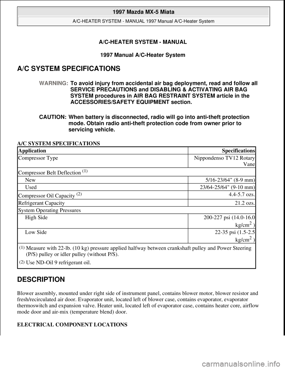
A/C SYSTEM SPECIFICATIONS
A/C SYSTEM SPECIFICATIONS
DESCRIPTION
Blower assembly, mounted under right side of instrument panel, contains blower motor, blower resistor and
fresh/recirculated air door. Evaporator unit, located left of blower case, contains evaporator, evaporator
thermoswitch and expansion valve. Heater unit, located left of evaporator case, contains heater core, airflow
mode door and air-mix (temperature blend) door.
ELECTRICAL COMPONENT LOCATIONS WARNING:To avoid injury from accidental air bag deployment, read and follow all
SERVICE PRECAUTIONS and DISABLING & ACTIVATING AIR BAG
SYSTEM procedures in AIR BAG RESTRAINT SYSTEM article in the
ACCESSORIES/SAFETY EQUIPMENT section.
CAUTION: When battery is disconnected, radio will go into anti-theft protection
mode. Obtain radio anti-theft protection code from owner prior to
servicing vehicle.
ApplicationSpecifications
Compressor TypeNippondenso TV12 Rotary
Vane
Compressor Belt Deflection (1)
New5/16-23/64" (8-9 mm)
Used23/64-25/64" (9-10 mm)
Compressor Oil Capacity (2) 4.4-5.7 ozs.
Refrigerant Capacity21.2 ozs.
System Operating Pressures
High Side200-227 psi (14.0-16.0
kg/cm
2 )
Low Side22-35 psi (1.5-2.5
kg/cm
2 )
(1)Measure with 22-lb. (10 kg) pressure applied halfway between crankshaft pulley and Power Steering
(P/S) pulley or idler pulley (without P/S).
(2)Use ND-Oil 9 refrigerant oil.
1997 Mazda MX-5 Miata
A/C-HEATER SYSTEM - MANUAL 1997 Manual A/C-Heater System
1997 Mazda MX-5 Miata
A/C-HEATER SYSTEM - MANUAL 1997 Manual A/C-Heater System
Microsoft
Sunday, July 05, 2009 1:41:48 PMPage 1 © 2005 Mitchell Repair Information Company, LLC.
Microsoft
Sunday, July 05, 2009 1:41:59 PMPage 1 © 2005 Mitchell Repair Information Company, LLC.
Page 326 of 514

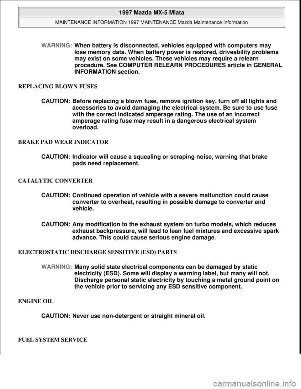
REPLACING BLOWN FUSES
BRAKE PAD WEAR INDICATOR
CATALYTIC CONVERTER
ELECTROSTATIC DISCHARGE SENSITIVE (ESD) PARTS
ENGINE OIL
FUEL SYSTEM SERVICE WARNING:When battery is disconnected, vehicles equipped with computers may
lose memory data. When battery power is restored, driveability problems
may exist on some vehicles. These vehicles may require a relearn
procedure. See COMPUTER RELEARN PROCEDURES article in GENERAL
INFORMATION section.
CAUTION: Before replacing a blown fuse, remove ignition key, turn off all lights and
accessories to avoid damaging the electrical system. Be sure to use fuse
with the correct indicated amperage rating. The use of an incorrect
amperage rating fuse may result in a dangerous electrical system
overload.
CAUTION: Indicator will cause a squealing or scraping noise, warning that brake
pads need replacement.
CAUTION: Continued operation of vehicle with a severe malfunction could cause
converter to overheat, resulting in possible damage to converter and
vehicle.
CAUTION: Any modification to the exhaust system on turbo models, which reduces
exhaust backpressure, will lead to lean fuel mixtures and excessive spark
advance. This could cause serious engine damage.
WARNING:Many solid state electrical components can be damaged by static
electricity (ESD). Some will display a warning label, but many will not.
Discharge personal static electricity by touching a metal ground point on
the vehicle prior to servicing any ESD sensitive component.
CAUTION: Never use non-detergent or straight mineral oil.
1997 Mazda MX-5 Miata
MAINTENANCE INFORMATION 1997 MAINTENANCE Mazda Maintenance Information
Microsoft
Sunday, July 05, 2009 1:41:19 PMPage 6 © 2005 Mitchell Repair Information Company, LLC.
Page 336 of 514

STEERING SYSTEM - POWER RACK & PINION
1997 STEERING Mazda Power Rack & Pinion
DESCRIPTION
Steering system is a power-assisted rack and pinion. The system consists of a rack and pinion steering gear and
power-assist pump/reservoir. The steering gear and pump/reservoir are connected by flexible lines.
TESTING
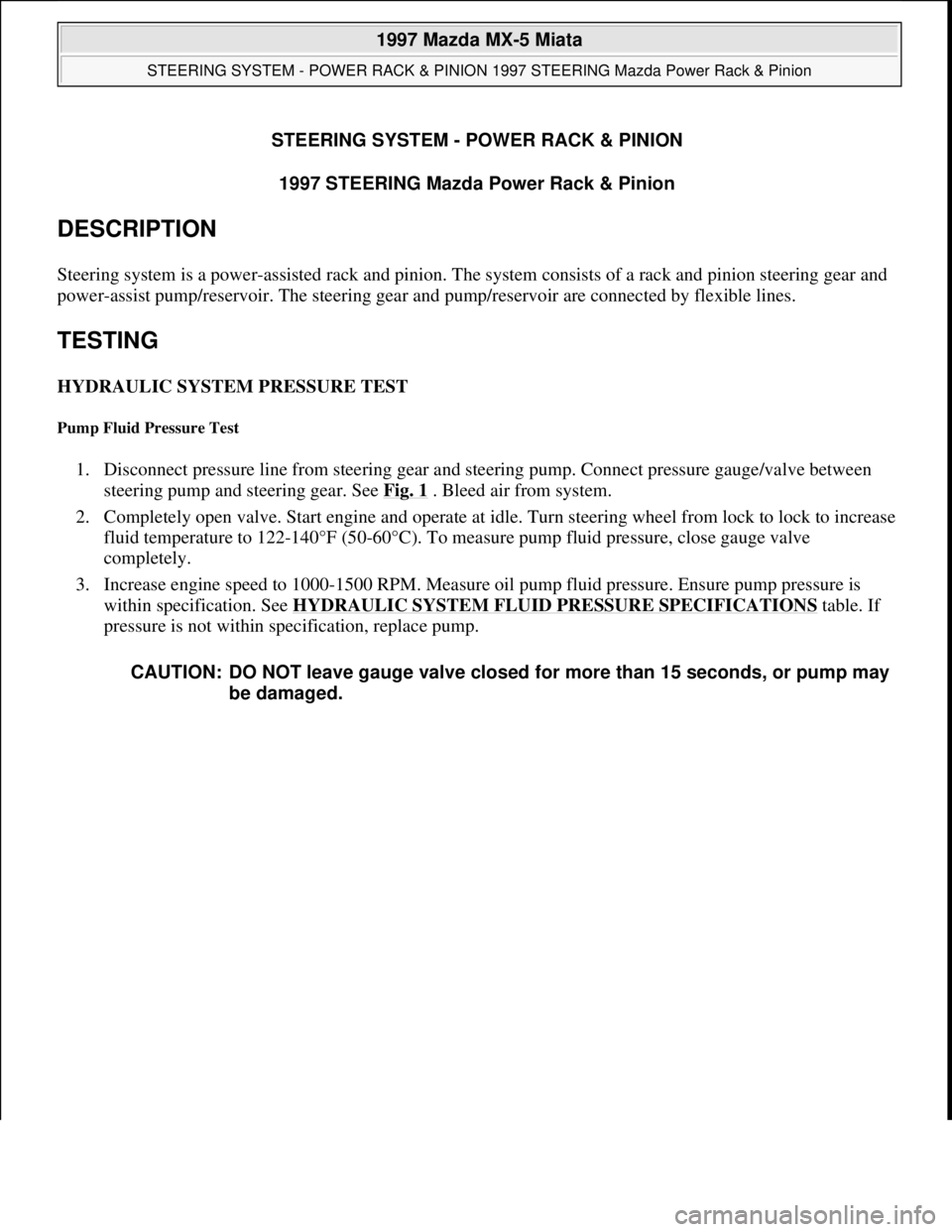
HYDRAULIC SYSTEM PRESSURE TEST
Pump Fluid Pressure Test
1. Disconnect pressure line from steering gear and steering pump. Connect pressure gauge/valve between
steering pump and steering gear. See Fig. 1
. Bleed air from system.
2. Completely open valve. Start engine and operate at idle. Turn steering wheel from lock to lock to increase
fluid temperature to 122-140°F (50-60°C). To measure pump fluid pressure, close gauge valve
completely.
3. Increase engine speed to 1000-1500 RPM. Measure oil pump fluid pressure. Ensure pump pressure is
within specification. See HYDRAULIC SYSTEM FLUID PRESSURE SPECIFICATIONS
table. If
pressure is not within specification, replace pump.
CAUTION: DO NOT leave gauge valve closed for more than 15 seconds, or pump may
be damaged.
1997 Mazda MX-5 Miata
STEERING SYSTEM - POWER RACK & PINION 1997 STEERING Mazda Power Rack & Pinion
1997 Mazda MX-5 Miata
STEERING SYSTEM - POWER RACK & PINION 1997 STEERING Mazda Power Rack & Pinion
Microsoft
Sunday, July 05, 2009 1:39:26 PMPage 1 © 2005 Mitchell Repair Information Company, LLC.
Microsoft
Sunday, July 05, 2009 1:39:30 PMPage 1 © 2005 Mitchell Repair Information Company, LLC.