1997 HONDA CR-V Egr
[x] Cancel search: EgrPage 31 of 1395

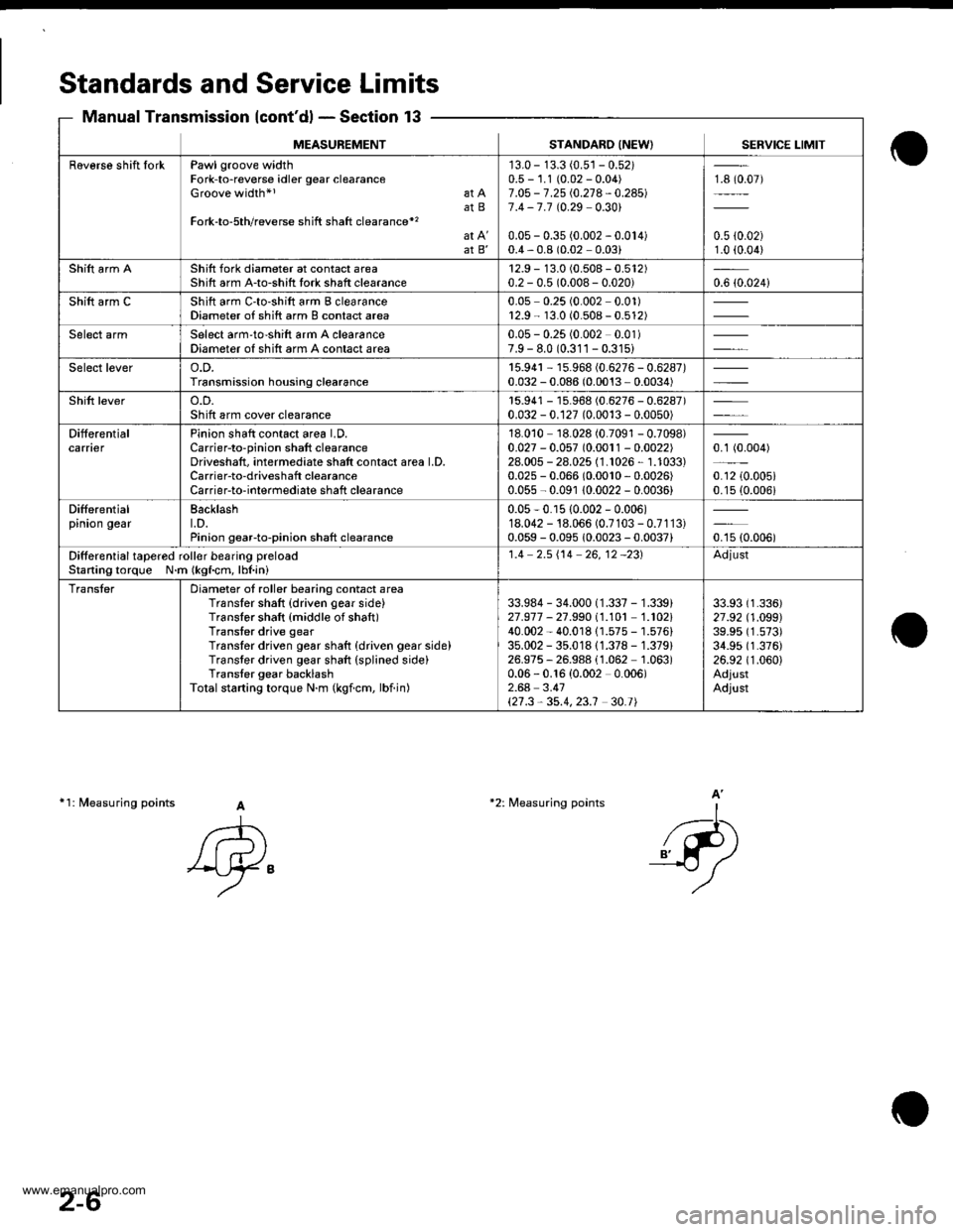
Standards and Service Limits
Manual Transmission {cont'd} - Section 13
11: fuleasuring points A
A
'Ay"
-l-...
_{-P)
A'*2: Measuring points
MEASUREMENTSTANDARO INEW) SERVICE LIMIT
Raverse shift IorkPawl groove widthFork-to-reverse idler gear clearanceGroove width*l at AatBFork-to-5th/reverse shift shaft clearance*'�
at B'
'13.0 - 13.3 (0.5'�j - 0.52)0.5 - 1.1 (0.02 - 0.04)7.O5 - 7.25 i.0.21 4 - 0.24517.4 -7.7 t0.29 0.301
0.05 - 0.35 (0.002 - 0.014)0.4,0.8 (0.02 0.03)
18 (0.07)
0.5 {0.02)1.0 (0.04)
Shift arm AShift fork diameter at contact areaShift arm A-to-shitt tork shaft clearance12.9 - 13.0 (0.508 - 0.512)0.2 - 0.5 (0.008- 0.020)0.6 {0.024i
Shift arm CShift arm C'to-shift arm B clearanceDiameter of shift arm B contact area0.05 0.25 (0.002 0.01)r2.9 - 13.0 (0.508 - 0.512)
Select armSelect arm'to-shift arm A clearanceDiameter of shift arm A contact area0.05 - 0.25 (0.002 0.01)7.9 - 8.0 (0.311 - 0.31s)
Select levero.D.Transmission housing clearance15.94r - 15.968 (0.6276 - 0.6287)0.032 - 0.086 (0.0013 - 0.0034)
Shift levero.D.Sh ift arm cover clearancer5.941 - 15.968 (0.6276 - 0.6287)0.032 - 0.127 (0.0013 - 0.0050)
DifferentialcarnerPinion shaft contact area LD.Carrier-to-pinion shaft clearanceDriveshaft, intermediate shatt contact area LD,Carrier-to-driveshaft clearanceCarrierto-interrnediate shaft clearance
18.010 18.028 (0.7091 - 0.7098)0.027 - 0.057 (0.0011 - 0.0022)28.005 - 28.025 (1.1026, 1.1033)0.025 - 0.066 (0.0010,0.0026)
0.055 - 0.091 10.0022 - 0.0036)
0.1 (0.004)
0.12 {0.005i0.15 (0.006i
Differentialpinion gearBacklasht.D.Pinion gearto-pinion shaft clearance
0.05-0.r5 {0.002 - 0.006)18.042 - 18.066 (0.7103 - 0.7113)0.059 - 0.095 10.0023 - 0.0037)oru ro.ooor
Ditferential tapered roll€r besring preloacStaning torque N.m (kgf.cm, lbl.ini
1.4 2.5i'14 26,12 -231Adjust
TransterDiameter of roller bearing contact areaTransler shaft {driven gear side}Translor shaft {middle of shaft)Transter drive gearTranslor driven gear shaft {driven gear side)Transter driven gear shaft (splined side)Trans{er gear backlashTotalstarting torque N.m (kgicm, lbiin)
33.984 - 34.000 (1.337 - 1.339)21.977 - 27.99011.101 1.102140.002 - 40.01811.575 - 1.576)35.002 - 35.01811.378 - 1.379)26.975, 26.988 (1.062 1.063)0.06 - 0.16 {0.002 0.006)2.64 3.41\21.3,35.4,23.1 30.t|
33.93 (1.336)
27 .92 (1 .O99)39.95 (1.573)
34.95 (1.376)
26.92 (1.060)
AdjustAdjust
2-6
www.emanualpro.com
Page 145 of 1395

Cylinder Head
Installation (cont'dl
'13. Align the marks on the cylinder head plug to thecylinder head upper surface, then install the cylin
der head plug in the end of the cylinder head.
CYLINOER HEADPLUGReplace.
lnstallthe back cover.
To set the camshafts at TDC position for the No. lpiston, align the holes in the camshafts with theholes in the No. l camshaft holders and insert 5.0mm pin punches in the holes. Install the keys into
the camshaft grooves.
37 N m (3.8 *gl.m, 27 lbt.tr)
9.8 N.m (1.0 kgtm,7.2|hrftl
Push the camshaft pulleys onto the camshafts. thentighten the retaining bolts to the torque specified.
6-32
14.
KEYS
I x 1.25 mm
6x1.0mm
Install the timing belt (see page 6-1 1).
Adjust the valve clearance (see page 6-3).
Thoroughly clean the head cover gasket and thegroove.
lnstall the head cover gasket in the groove of thecylinder head cover. Seat the head cover gasket in
the recesses for the camshaft first, then work it into
the groove around the outside edges. Make sure thehead cover gasket is seated securely in the corners
of the recesses with no gap.
17.
'18.
19.
www.emanualpro.com
Page 288 of 1395

PGM-FI System
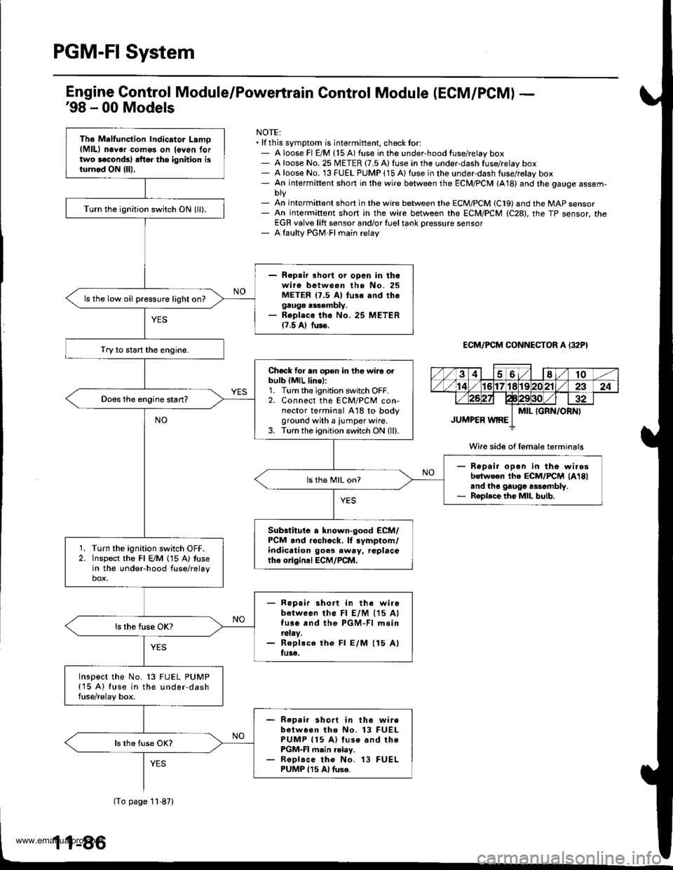
Tho Maltunction Indicator Lamo(MlL) n6Yor como3 on leven lortwo laconds) rft6r tho ignhion isturnod ON {lll.
Turn th6 ignition switch ON (ll).
- Repair lhort or opcn in thowire between the No. 25METER 17.5 Al fu3e snd thegauge assembly.- Repl.co the No. 25 METER17.5 Al fus€.
ls the low oil pressure light on?
Try to start the engine.
Chock for an opsn in th€ wiro orbulb {MlL line,:1. Turn the ignition switch OFF.2. Connect the ECM/PCM con-nector terminal A18 to bodyground with a iumper wire.3. Turn the ignition switch ON (ll).
Rep.ir open in the wi.osbotween the ECM/FCM lA18land the gaugo rasombly.Roplece the MIL bulb.
ls th6 MIL on?
Substitute a known-good ECM/PCM and rochock. lf rymptom/indication goes eway, replacetho o gind ECM/PCM.
Turn the ignition switch OFF.Inspect the Fl E/M 115 A) tusein the undeFhood fuse/relaybox.
- Repair short in the wirebetween lhe Fl E/M (15 AlfusG and the PGM-Fl m.in.slay.- Roplsce th€ Fl E/M (15 Alfu3€.
Inspect the No. 13 FUEL PUMP(15 A) fuse in the under-dashfuse/relay box.
- Repair short in th6 wirebetween tho No. 13 FUELPUMP 115 A) luse and thePGM-FI main .elay.- ReDlace tho No. 13 FUELPUMP 115 Al tuse.
Engine Gontrol Module/Powertrain Control Module (ECM/PCM) -'98 - 00 Models
NOTE:. lf this symptom is intermittent, check tor:- A loose Fl E/M {15 A) fuse in the under-hood fuse/relay box- A loose No. 25 METER {7.5 A) fuse in the under-dash fuse/relay box- A loose No. 13 FUEL PUMP (15 Alfuse in the underdash fuse/rolay box- An intermiftent short in the wire between the ECM/PCM (A18) and the gauge assem-
- An int€rmiftent short in the wire between the ECM/PCM (C19) and the MAP sensor- An intermiftent short in the wire between rhe ECM/PCM (C28), the TP sensor, theEGR valve lift sensor and/or {uel tank Dressure sensor- A laulty PGM-FI main relay
ECM/PCM CONNECTOR A (32P}
Wire side of female terminals
(To page 11-871
www.emanualpro.com
Page 337 of 1395
![HONDA CR-V 1997 RD1-RD3 / 1.G Workshop Manual
Vehicle Speed Sensor (VSSI
lPosoo-]-. |posol l-
97 modol:
The scan tool indicates Diagnostic Trouble Code {DTC} P0500*�or P0501*r: A range/perfor-
mance in the Vehicle Speed Sensor (VSS) circuit. HONDA CR-V 1997 RD1-RD3 / 1.G Workshop Manual
Vehicle Speed Sensor (VSSI
lPosoo-]-. |posol l-
97 modol:
The scan tool indicates Diagnostic Trouble Code {DTC} P0500*�or P0501*r: A range/perfor-
mance in the Vehicle Speed Sensor (VSS) circuit.](/manual-img/13/5778/w960_5778-336.png)
Vehicle Speed Sensor (VSSI
lPosoo-]-'. |posol l-'
'97 modol:
The scan tool indicates Diagnostic Trouble Code {DTC} P0500*'�or P0501*r: A range/perfor-
mance in the Vehicle Speed Sensor (VSS) circuit. * I ; A/T*2i Mfi
FCM CONNECTORS
A t32Pl
LG1(BRN/BLK)
NOTE: Do not use the engine to turn thofront wheels with th6 rear wheels on theground. The 4WD system will engage andthe vehicle will suddenlv Iurch forward.
Wire side ot female terminals
LGl
{BRN/BLKI
(cont'd)
11-135
The MIL hes boen roported on.DTC m501 is 3tor€d.
Problom verificetion:1. Test'drive the vohicle.2. Check the vehicle speed withthe scan tool,
lntormittent tailure, rystom b OKat thia timo. Chock tor poor con-nection3 or 10o3o wires rt C129lvss) .nd rr rhe Pcfr4,
ls the correct speed indicated?
Chock for an open in tho PiCM:1. Turn the ignition switch OFF.2. Block the rear wheels and setthe parking brake.3. Jack up the lront of the vehicleand support it with saletystands.4. Turn the ignition switch ON (ll).
5. Elock the right front wheel andslowly rotate the left trontwheel by hand.6. Measure voltage betweenPCM connector terminals C18and A9.
Substitulc a known-good PCMand .och6ck. It symptom/indicd.tion go.a away, .cplaco tho origi-nel FCM.
Doesthe voltage pulse 0 Vand 5 V or battery voltage?
Check for a .hort in the PCM:L Turn the ignition switch OFF.2. Disconnect the PCM con'nector C (31P).
3. Turn the ignition switch ON (ll).
4. Elock the right front wheeland slowly rotate the left front
5. Measure vohage between PCMconnector terminals C18 andA9.
Substituto e known-good PCMand rochock. f rymptom/indica-tion goos rwry, roplsc. tho origi-nalFCM.
Doesthe voltage pulse 0 Vand 5 V or battery voltage?
- Repair short in the wirebetween the PCM lC18l,cruise control unit, speodo-meter, and VSS,- Repair opon in the wirebetween the PCM {C181 .ndrhe vss.- f wire is OK. tost lho VSS l3oosoction 231.
www.emanualpro.com
Page 338 of 1395

PGM-FI System
Vehicle Speed Sensor (VSSI {cont'd}
'98 - 00 models:
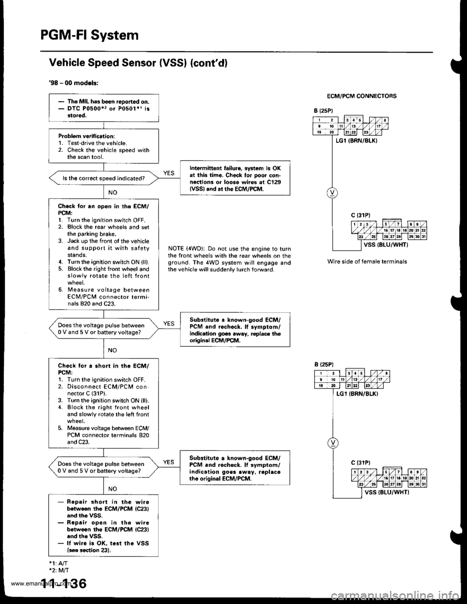
ECM/PCM CONNECTORS
B t25Pl
NOTE (4WD): Do not use the engine to turnthe front wheels with the rear wheels on theground. The 4WD system will engage andthe vehicle will suddenly lurch forward.
Wire side of female terminals
- The MIL ha3 been reDoned on.- DTC P0500" or P0501*1 i33torod.
Probl6m verification:1. Test-drive the vehicle.2. Check the vehicle speed withthe scan tool,
Intermittont failu.e, svstem is OKat thk time. Check for poor con-nection! or loose wiros at C129lvss) .nd ar the EcM/PcM.
ls the correct speed indicated?
Check for rn open in the ECM/PCM:l� Turn the ignition switch OFF.2. Elock the rear wheels and setthe parking brake.3. Jack up the front oI the vehicleand support it with satetystands.4. Turn the ignition switch ON {ll}.5. Block the right front whoel andslowly rotate the lett front
6. Measure voltage betweenECM/PCM connector termi-nals 820 and C23.
Substitute a known-good ECM/PCM and rochock. ll symptom/indicetion 9063 away, .oplace th€origin.l ECM/PCM.
Does the voltage pulse between0 V and 5 V or battery voltage?
Check for a short in the ECM/PCMI1. Turn the ignition switch OFF.2. Disconnect ECM/PCM connector C 131P).3. Turn the ignition swilch ON {ll).4. Block the right front wheeland slowly rotate the left front
5. Moasure voltage between ECM/PCM connector terminals 820and C23.
Sub.titute a known-good ECM/PCM and rschock. It rymptom/indication goos .w.y. replecerhe original ECM/PCM.
Does the voltage pulse betlveen0 V and 5 V or battery voltage?
- R.pair short in the wirobetwe€n the ECM/PCM lC23).nd tho VSS.- Roprir open in th6 wirebotweon the ECM/PCM lc23land th6 vss.- It wirc is OK, te3t ihe VSS(!€e soetion 23).
B (25P)
1
*2:Mft
1-136
www.emanualpro.com
Page 404 of 1395

Emission Control System
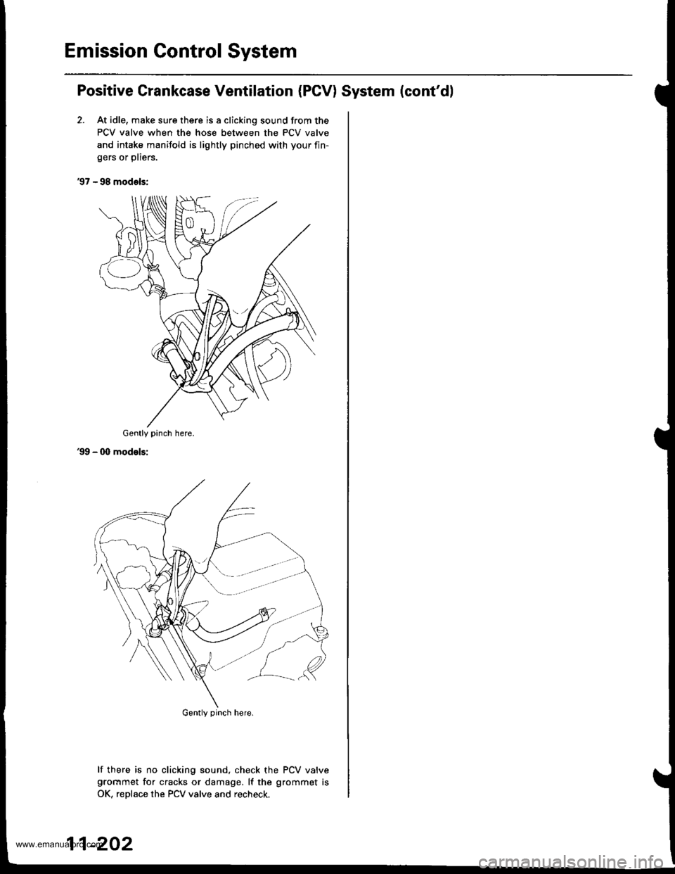
Positive Crankcase Ventilation (PCV) System (cont'dl
2. At idle, make sure there is a clicking sound from the
PCV valve when the hose between the PCV valve
and intake manifold is lightly pinched with your fin-
gers or pliers.
'97 - 98 models:
'99 - 00 modelsi
lf there is no clicking sound, check the PCV valvegrocrmet for cracks or damage, lf the grommet is
OK, reDlace the PCV valve and recheck.
Gently pinch here.
Gently pinch here.
11-202
www.emanualpro.com
Page 475 of 1395

Synchro Sleeve, Synchro Hub
Inspection
1.Inspect gear teeth on all synchro hubs and synchro
sleeves for rounded off corners, which indicate
Install each synchro hub in its mating synchro
sleeve, and check for freedom of movement.
NOTE: lf replacement is required, always replace
the synchro sleeve and synchro hub as a set.
SYNCHROSLEEVE
SYNCHBOHUB
13-36
LONGER ?EETH
Installation
When assembling the synchro sleeve and synchro hub,
be sure to match the three sets of longer teeth ('120
degrees apart) on the synchro sleeve with the three sets
of deeper grooves in the synchro hub. Do not installthe
synchro sleeve with its longer teeth in the lsv2nd syn-
chro hub slots because it will damage the spring ring.
SYNCHRO
SYNCHBOSI.EEVE
www.emanualpro.com
Page 505 of 1395

Mainshaft Thrust Clearance
Adjustment (cont'dl
-7. Slide the mainshaft base over the mainshaft.
Attach the mainshaft holder to the mainshaft as
follows:
NOTE:
. Back-out the mainshaft holder bolt and
loosen the two hex bolts.
. Fit the holder over the mainshaft so its lip is
towards the transmission.
. Align the mainshaft holder's lip around the
groove at the inside of the mainshaft
splines, then tighten the hex bolts.
MAINSHAFT HOLDERBOLT
MAINSHAFT EASE07GAJ - PG20130
-9. Seat the mainshaft fully by tapping its end with
a plastic hammer.
-10. Thread the mainshaft holder bolt in until it just
contacts the wide surface of the mainshaft
base.
07GAJ - PG20130
-8.
t--E-Hlf\f,A l\. xex
l"\y I aors
t____=__)"n-____"8
\
MAINSHAFTHOLDER07GAJ - PG20110
- 11. Zero a dial gauge onthe end ofthe mainshait.
-12. Turn the mainshaft holder bolt clockwise; stop
turning when the dial gauge has reached its
maximum movement, The reading on the dial
gauge is the amount of mainshaft end play.
NOTE: Turning the mainshaft holder bolt more
than 60 degrees after the needle of the dial
gauge stops moving may damage the transmis-
sion.
MAINSHAFT HOLDER07cru - PG20110
-13. lf the reading is within the standard, the clear-
ance rs correct.
lf the reading is not within the standard,
recheck the shim thickness.
Standard: 0.11 - 0.18 mm (0.00i1- 0.007 inl
DIAL GAUGEMAGNET STAND AASE07979 - PJ40001
www.emanualpro.com